Page 39 of 3115
AC1IL-03
I08106
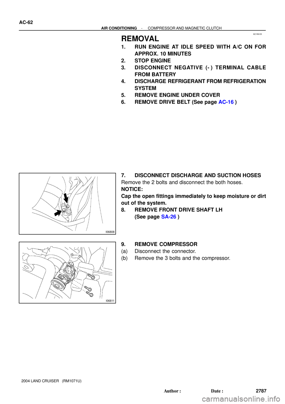
Suction HoseDischarge Hose
Front Drive Shaft LH
Engine Under Cover
Compressor Stator
� Snap RingRotor
Shim Pressure Plate
49 (500, 36)
13.2 (135, 9)
10 (100, 7)
49 (500, 36)
Drive Belt
Compressor and
Magnetic Clutch
� O-ring
I06761
I06762
N´m (kgf´cm, ft´lbf) : Specified torque
� Non reusable part
- AIR CONDITIONINGCOMPRESSOR AND MAGNETIC CLUTCH
AC-61
2786 Author�: Date�:
2004 LAND CRUISER (RM1071U)
COMPONENTS
Page 43 of 3115
AC1IP-04
I06811
I06808
- AIR CONDITIONINGCOMPRESSOR AND MAGNETIC CLUTCH
AC-67
2792 Author�: Date�:
2004 LAND CRUISER (RM1071U)
INSTALLATION
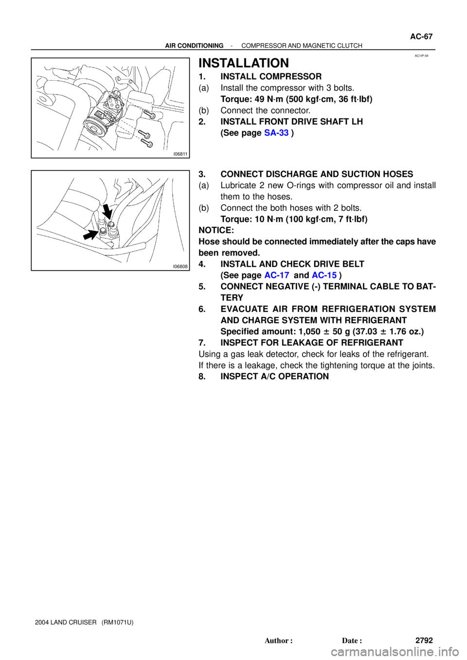
1. INSTALL COMPRESSOR
(a) Install the compressor with 3 bolts.
Torque: 49 N´m (500 kgf´cm, 36 ft´lbf)
(b) Connect the connector.
2. INSTALL FRONT DRIVE SHAFT LH
(See page SA-33)
3. CONNECT DISCHARGE AND SUCTION HOSES
(a) Lubricate 2 new O-rings with compressor oil and install
them to the hoses.
(b) Connect the both hoses with 2 bolts.
Torque: 10 N´m (100 kgf´cm, 7 ft´lbf)
NOTICE:
Hose should be connected immediately after the caps have
been removed.
4. INSTALL AND CHECK DRIVE BELT
(See page AC-17 and AC-15)
5. CONNECT NEGATIVE (-) TERMINAL CABLE TO BAT-
TERY
6. EVACUATE AIR FROM REFRIGERATION SYSTEM
AND CHARGE SYSTEM WITH REFRIGERANT
Specified amount: 1,050 ± 50 g (37.03 ± 1.76 oz.)
7. INSPECT FOR LEAKAGE OF REFRIGERANT
Using a gas leak detector, check for leaks of the refrigerant.
If there is a leakage, check the tightening torque at the joints.
8. INSPECT A/C OPERATION
Page 46 of 3115
AC1IM-03
I06808
I06811
AC-62
- AIR CONDITIONINGCOMPRESSOR AND MAGNETIC CLUTCH
2787 Author�: Date�:
2004 LAND CRUISER (RM1071U)
REMOVAL
1. RUN ENGINE AT IDLE SPEED WITH A/C ON FOR
APPROX. 10 MINUTES
2. STOP ENGINE
3. DISCONNECT NEGATIVE (- ) TERMINAL CABLE
FROM BATTERY
4. DISCHARGE REFRIGERANT FROM REFRIGERATION
SYSTEM
5. REMOVE ENGINE UNDER COVER
6. REMOVE DRIVE BELT (See page AC-16)
7. DISCONNECT DISCHARGE AND SUCTION HOSES
Remove the 2 bolts and disconnect the both hoses.
NOTICE:
Cap the open fittings immediately to keep moisture or dirt
out of the system.
8. REMOVE FRONT DRIVE SHAFT LH
(See page SA-26)
9. REMOVE COMPRESSOR
(a) Disconnect the connector.
(b) Remove the 3 bolts and the compressor.
Page 52 of 3115
AC1HR-03
- AIR CONDITIONINGDRIVE BELT
AC-17
2742 Author�: Date�:
2004 LAND CRUISER (RM1071U)
INSTALLATION
Installation is in the reverse of removal (See page AC-16).
Page 53 of 3115
CH0086
Correct Wrong
AC1HP-03
B00808
A
B
- AIR CONDITIONINGDRIVE BELT
AC-15
2740 Author�: Date�:
2004 LAND CRUISER (RM1071U)
DRIVE BELT
ON-VEHICLE INSPECTION
1. INSPECT DRIVE BELT'S INSTALLATION CONDITION
Check that drive belt fits properly in the ribbed grooves.
2. INSPECT DRIVE BELT TENSION
Check that the tension is within A range on the auto tensioner
scale.
If the tension is not within the A range on the scale, replace the
belt with a new one.
HINT:
When replacing the drive belt with a new one, the belt's tension
should be within the B range on the belt tensioner scale.
Page 54 of 3115
AC1HQ-03
EM6656
AC-16
- AIR CONDITIONINGDRIVE BELT
2741 Author�: Date�:
2004 LAND CRUISER (RM1071U)
REMOVAL
REMOVE DRIVE BELT
Loosen the drive belt tension by turning the drive belt tensioner
counterclockwise, and remove the drive belt.
Page 127 of 3115
AT12V-01
D12652
(a)
(b)
(b)
(c)
Lock
D12653
D12654
D12655
AT-30
- AUTOMATIC TRANSMISSIONAUTOMATIC TRANSMISSION UNIT
1884 Author�: Date�:
2004 LAND CRUISER (RM1071U)
REMOVAL
1. REMOVE BATTERY
2. REMOVE AIR CLEANER CAP DRIVE BELT, FAN AND
FLUID COUPLING ASSEMBLY, FAN SHROUD AND
RADIATOR RESERVOIR
(See page CO-17)
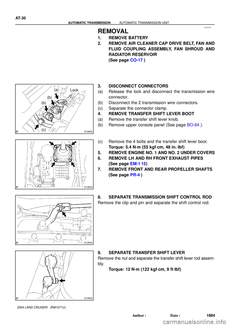
3. DISCONNECT CONNECTORS
(a) Release the lock and disconnect the transmission wire
connector.
(b) Disconnect the 2 transmission wire connectors.
(c) Separate the connector clamp.
4. REMOVE TRANSFER SHIFT LEVER BOOT
(a) Remove the transfer shift lever knob.
(b) Remove upper console panel (See page BO-84).
(c) Remove the 4 bolts and the transfer shift lever boot.
Torque: 5.4 N´m (55 kgf´cm, 48 in.´lbf)
5. REMOVE ENGINE NO. 1 AND NO. 2 UNDER COVERS
6. REMOVE LH AND RH FRONT EXHAUST PIPES
(See page EM-1 15)
7. REMOVE FRONT AND REAR PROPELLER SHAFTS
(See page PR-4)
8. SEPARATE TRANSMISSION SHIFT CONTROL ROD
Remove the clip and pin and separate the shift control rod.
9. SEPARATE TRANSFER SHIFT LEVER
Remove the nut and separate the transfer shift lever rod assem-
bly.
Torque: 12 N´m (122 kgf´cm, 9 ft´lbf)
Page 210 of 3115
I24919
OIL
SEAT BELTD1 D2 ODO/TRIP
INCLINATION
SSR
EEPRON
BZ
SPD
TM
FUEL
TEMP
VOLT
SUPPLY
CIRCUIT
P
R
D N
4
3
L 2
A/T P
CRUISE
2nd START
ETC PWR
AIR BAG
FUEL WARNING
CHG
A/T OIL TEMP D6
D11
D5
D19
D14
D16
D12
C19
B10
C20
C4
D10
D9
D17OIL MAINT
- BODY ELECTRICALCOMBINATION METER
BE-59
2432 Author�: Date�:
2004 LAND CRUISER (RM1071U)