1986 TOYOTA LAND CRUISER ignition
[x] Cancel search: ignitionPage 2204 of 3115
2004 LAND CRUISER (EWD548U)
197
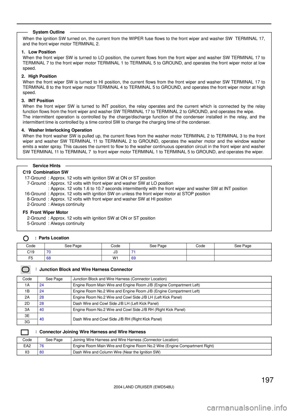
When the ignition SW turned on, the current from the WIPER fuse flows to the front wiper and washer SW TERMINAL 17,
and the front wiper motor TERMINAL 2.
1. Low Position
When the front wiper SW is turned to LO position, the current flows from the front wiper and washer SW TERMINAL 17 to
TERMINAL 7 to the front wiper motor TERMINAL 1 to TERMINAL 5 to GROUND, and operates the front wiper motor at low
speed.
2. High Position
When the front wiper SW is turned to HI position, the current flows from the front wiper and washer SW TERMINAL 17 to
TERMINAL 8 to the front wiper motor TERMINAL 4 to TERMINAL 5 to GROUND, and operates the front wiper motor at high
speed.
3. INT Position
When the front wiper SW is turned to INT position, the relay operates and the current which is connected by the relay
function flows from the front wiper and washer SW TERMINAL 17 to TERMINAL 2 to GROUND, and operates the wipe.
The intermittent operation is controlled by the charge/discharge function of the condenser installed in the relay, and the
intermittent time is controlled by a time control SW to change the charging time of the condenser.
4. Washer Interlocking Operation
When the front washer SW is pulled up, the current flows from the washer motor TERMINAL 2 to TERMINAL 3 to the front
wiper and washer SW TERMINAL 11 to TERMINAL 2 to GROUND, operates the washer motor and the window washer
emits a water spray. This causes the current to flow to the washer continuous operation circuit in the front wiper and washer
SW TERMINAL 11 to TERMINAL 7 to front wiper motor TERMINAL 1 to TERMINAL 5 to GROUND, and operates the wiper.
C19 Combination SW
17-Ground : Approx. 12 volts with ignition SW at ON or ST position
7-Ground : Approx. 12 volts with front wiper and washer SW at LO position
: Approx. 12 volts 1.6 to 10.7 seconds intermittently with the front wiper and washer SW at INT position
16-Ground : Approx. 12 volts with ignition SW on unless the front wiper motor at STOP position
8-Ground : Approx. 12 volts with front wiper and washer SW at HI position
2-Ground : Always continuity
F5 Front Wiper Motor
2-Ground : Approx. 12 volts with ignition SW at ON or ST position
5-Ground : Always continuity
: Parts Location
CodeSee PageCodeSee PageCodeSee Page
C1970J371
F568W169
:Junction Block and Wire Harness Connector
CodeSee PageJunction Block and Wire Harness (Connector Location)
1A24Engine Room Main Wire and Engine Room J/B (Engine Compartment Left)
1B24Engine Room No.2 Wire and Engine Room J/B (Engine Compartment Left)
2A28Engine Room No.2 Wire and Cowl Side J/B LH (Left Kick Panel)
2D28Dash Wire and Cowl Side J/B LH (Left Kick Panel)
3A40Engine Room No.2 Wire and Cowl Side J/B RH (Right Kick Panel)
3E40Dash Wire and Cowl Side J/B RH (Right Kick Panel)3G40Dash Wire and Cowl Side J/B RH (Right Kick Panel)
:Connector Joining Wire Harness and Wire Harness
CodeSee PageJoining Wire Harness and Wire Harness (Connector Location)
EA276Engine Room Main Wire and Engine Room No.2 Wire (Engine Compartment Right)
II380Dash Wire and Column Wire (Near the Ignition SW)
System Outline
Service Hints
Page 2208 of 3115
2004 LAND CRUISER (EWD548U)
201
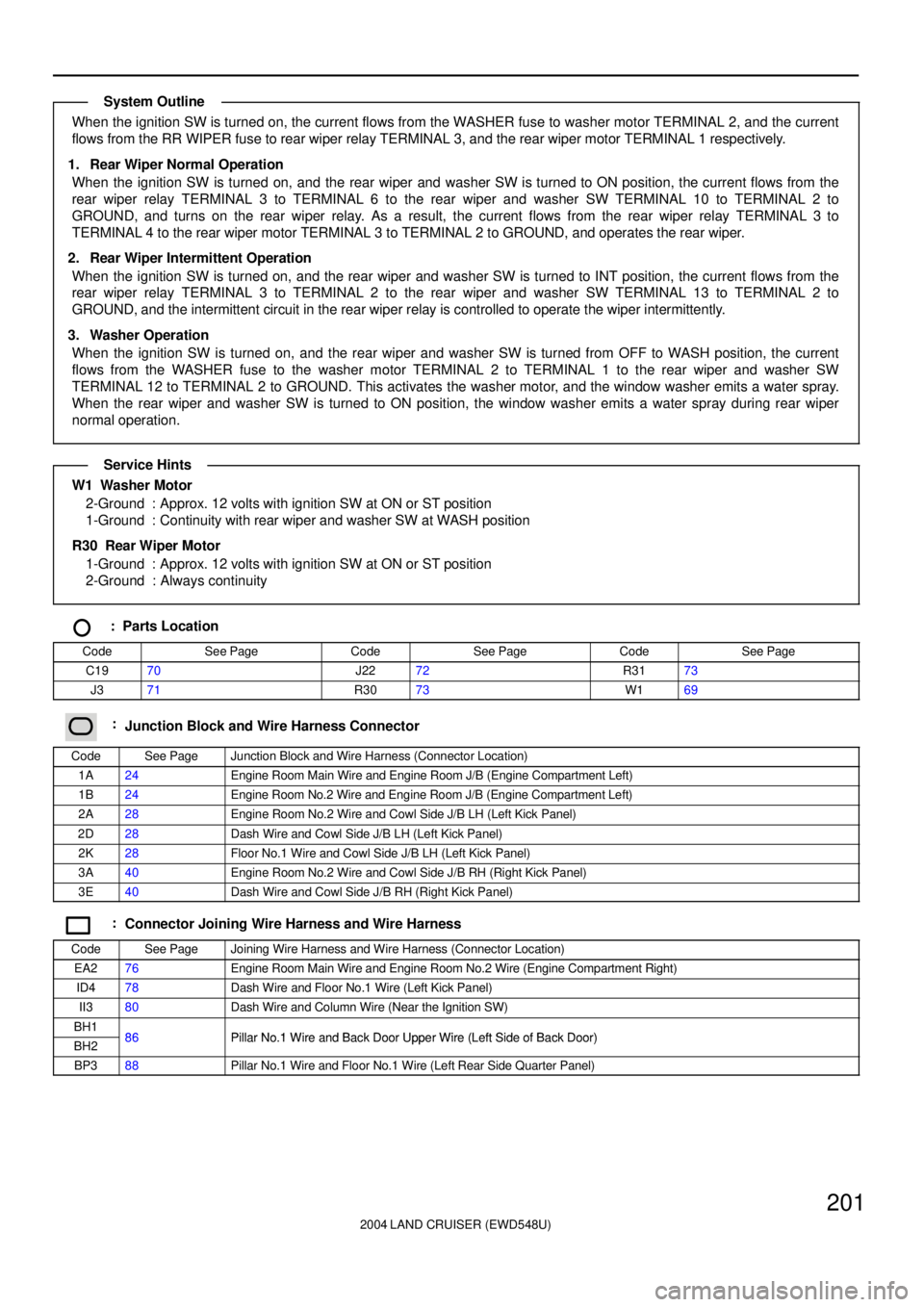
When the ignition SW is turned on, the current flows from the WASHER fuse to washer motor TERMINAL 2, and the current
flows from the RR WIPER fuse to rear wiper relay TERMINAL 3, and the rear wiper motor TERMINAL 1 respectively.
1. Rear Wiper Normal Operation
When the ignition SW is turned on, and the rear wiper and washer SW is turned to ON position, the current flows from the
rear wiper relay TERMINAL 3 to TERMINAL 6 to the rear wiper and washer SW TERMINAL 10 to TERMINAL 2 to
GROUND, and turns on the rear wiper relay. As a result, the current flows from the rear wiper relay TERMINAL 3 to
TERMINAL 4 to the rear wiper motor TERMINAL 3 to TERMINAL 2 to GROUND, and operates the rear wiper.
2. Rear Wiper Intermittent Operation
When the ignition SW is turned on, and the rear wiper and washer SW is turned to INT position, the current flows from the
rear wiper relay TERMINAL 3 to TERMINAL 2 to the rear wiper and washer SW TERMINAL 13 to TERMINAL 2 to
GROUND, and the intermittent circuit in the rear wiper relay is controlled to operate the wiper intermittently.
3. Washer Operation
When the ignition SW is turned on, and the rear wiper and washer SW is turned from OFF to WASH position, the current
flows from the WASHER fuse to the washer motor TERMINAL 2 to TERMINAL 1 to the rear wiper and washer SW
TERMINAL 12 to TERMINAL 2 to GROUND. This activates the washer motor, and the window washer emits a water spray.
When the rear wiper and washer SW is turned to ON position, the window washer emits a water spray during rear wiper
normal operation.
W1 Washer Motor
2-Ground : Approx. 12 volts with ignition SW at ON or ST position
1-Ground : Continuity with rear wiper and washer SW at WASH position
R30 Rear Wiper Motor
1-Ground : Approx. 12 volts with ignition SW at ON or ST position
2-Ground : Always continuity
: Parts Location
CodeSee PageCodeSee PageCodeSee Page
C1970J2272R3173
J371R3073W169
:Junction Block and Wire Harness Connector
CodeSee PageJunction Block and Wire Harness (Connector Location)
1A24Engine Room Main Wire and Engine Room J/B (Engine Compartment Left)
1B24Engine Room No.2 Wire and Engine Room J/B (Engine Compartment Left)
2A28Engine Room No.2 Wire and Cowl Side J/B LH (Left Kick Panel)
2D28Dash Wire and Cowl Side J/B LH (Left Kick Panel)
2K28Floor No.1 Wire and Cowl Side J/B LH (Left Kick Panel)
3A40Engine Room No.2 Wire and Cowl Side J/B RH (Right Kick Panel)
3E40Dash Wire and Cowl Side J/B RH (Right Kick Panel)
:Connector Joining Wire Harness and Wire Harness
CodeSee PageJoining Wire Harness and Wire Harness (Connector Location)
EA276Engine Room Main Wire and Engine Room No.2 Wire (Engine Compartment Right)
ID478Dash Wire and Floor No.1 Wire (Left Kick Panel)
II380Dash Wire and Column Wire (Near the Ignition SW)
BH186Pillar No 1 Wire and Back Door Upper Wire (Left Side of Back Door)BH286Pillar No.1 Wire and Back Door Upper Wire (Left Side of Back Door)
BP388Pillar No.1 Wire and Floor No.1 Wire (Left Rear Side Quarter Panel)
System Outline
Service Hints
Page 2212 of 3115
2004 LAND CRUISER (EWD548U)
205
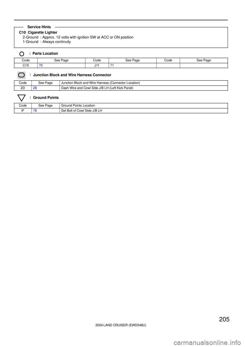
C10 Cigarette Lighter
2-Ground : Approx. 12 volts with ignition SW at ACC or ON position
1-Ground : Always continuity
: Parts Location
CodeSee PageCodeSee PageCodeSee Page
C1070J1171
:Junction Block and Wire Harness Connector
CodeSee PageJunction Block and Wire Harness (Connector Location)
2D28Dash Wire and Cowl Side J/B LH (Left Kick Panel)
:Ground Points
CodeSee PageGround Points Location
IF78Set Bolt of Cowl Side J/B LH
Service Hints
Page 2214 of 3115
2004 LAND CRUISER (EWD548U)
207
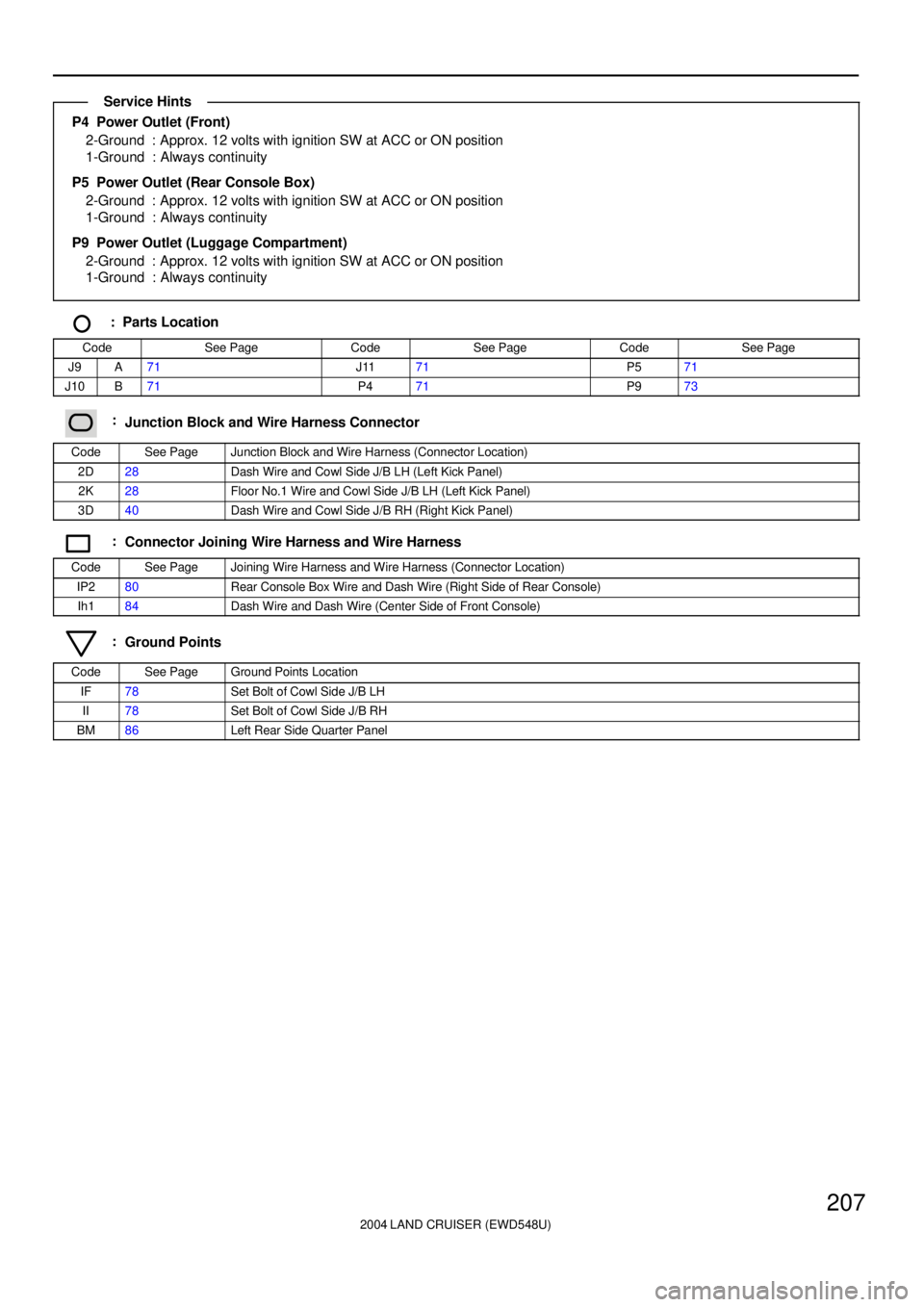
P4 Power Outlet (Front)
2-Ground : Approx. 12 volts with ignition SW at ACC or ON position
1-Ground : Always continuity
P5 Power Outlet (Rear Console Box)
2-Ground : Approx. 12 volts with ignition SW at ACC or ON position
1-Ground : Always continuity
P9 Power Outlet (Luggage Compartment)
2-Ground : Approx. 12 volts with ignition SW at ACC or ON position
1-Ground : Always continuity
: Parts Location
CodeSee PageCodeSee PageCodeSee Page
J9A71J1171P571
J10B71P471P973
:Junction Block and Wire Harness Connector
CodeSee PageJunction Block and Wire Harness (Connector Location)
2D28Dash Wire and Cowl Side J/B LH (Left Kick Panel)
2K28Floor No.1 Wire and Cowl Side J/B LH (Left Kick Panel)
3D40Dash Wire and Cowl Side J/B RH (Right Kick Panel)
:Connector Joining Wire Harness and Wire Harness
CodeSee PageJoining Wire Harness and Wire Harness (Connector Location)
IP280Rear Console Box Wire and Dash Wire (Right Side of Rear Console)
Ih184Dash Wire and Dash Wire (Center Side of Front Console)
:Ground Points
CodeSee PageGround Points Location
IF78Set Bolt of Cowl Side J/B LH
II78Set Bolt of Cowl Side J/B RH
BM86Left Rear Side Quarter Panel
Service Hints
Page 2216 of 3115
2004 LAND CRUISER (EWD548U)
209
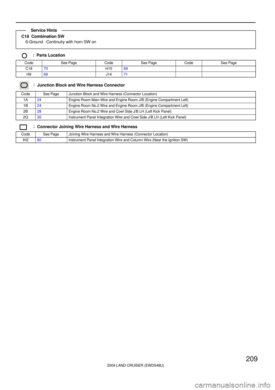
C18 Combination SW
6-Ground :Continuity with horn SW on
: Parts Location
CodeSee PageCodeSee PageCodeSee Page
C1870H1069
H969J1471
:Junction Block and Wire Harness Connector
CodeSee PageJunction Block and Wire Harness (Connector Location)
1A24Engine Room Main Wire and Engine Room J/B (Engine Compartment Left)
1B24Engine Room No.2 Wire and Engine Room J/B (Engine Compartment Left)
2B28Engine Room No.2 Wire and Cowl Side J/B LH (Left Kick Panel)
2Q30Instrument Panel Integration Wire and Cowl Side J/B LH (Left Kick Panel)
:Connector Joining Wire Harness and Wire Harness
CodeSee PageJoining Wire Harness and Wire Harness (Connector Location)
IH280Instrument Panel Integration Wire and Column Wire (Near the Ignition SW)
Service Hints
Page 2225 of 3115

2004 LAND CRUISER (EWD548U)
218Electronically Controlled Transmission and A/T Indicator
Previous automatic transmissions have selected each gear shift using mechanically controlled throttle hydraulic pressure,
governor hydraulic pressure and lock-up hydraulic pressure. The electronically controlled transmission, however, electrically
controls the line pressure, throttle pressure, lock-up pressure and accumulator pressure etc. through the solenoid valve. The
electronically controlled transmission is a system which precisely controls gear shift timing and lock-up timing in response to
the vehicle's driving conditions and the engine condition detected by various sensors. It makes smooth driving possible by
shift selection for each gear which is the most appropriate to the driving conditions at that time, and by preventing downing,
squat and gear shift shock when starting off.
1. Gear Shift Operation
When driving, the engine warm up condition is input as a signal to TERMINAL THW of the engine control module from the
engine coolant temp. sensor and the vehicle speed signal from vehicle speed sensor is input to TERMINAL SP2+ of the
engine control module. At the same time, the throttle valve opening signal from the throttle position sensor is input to
TERMINALS VTA1 and VTA2 of the engine control module as throttle angle signal.
Based on these signals, the engine control module selects the best shift position for the driving conditions and sends current
to the electronically controlled transmission solenoid.
2. Line Hydraulic Pressure Control
The engine control module adjusts the line hydraulic pressure to the optimal level by controlling TERMINAL SLT+ of the
module according to the engine torque data. This realizes the smooth gear shifting.
3. High Response Gear Shifting Control
The engine control module performs the high response engine torque up control to control the ignition-timing lag as well as
opening the electronic throttle when shifting down. By doing this, the gear shifting is performed in a short period of time.
Moreover, the engine control module uses the orifice switching control, which optimizes the speed of applying and reducing
the hydraulic pressure. And it realizes the fine shifting condition by applying and reducing hydraulic pressure slowly when
the gear shifting shock is important and quickly when the high response is required.
4. Clutch Hydraulic Pressure Control
The engine control module controls the clutch operation in the optimal timing and with the best hydraulic pressure according
to the engine torque data and the number of the clutch revolution
5. Lock-Up and Flexible Lock-Up Control
The engine control module carries out the lock-up control by controlling the TERMINAL SLU+ of the module according to
the shift position, vehicle speed, throttle opening degree and running conditions. The engine control module also steadily
keeps applying the lock-up clutch a delicate slippage to improve the transmission efficiency (Fuel efficiency) of the torque
converter.
6. Stop Light SW Circuit
If the brake pedal is depressed (Stop light SW on) when driving in lock-up condition, a signal is input to TERMINAL STP of
the engine control module. The engine control module operates and cuts the current to the solenoid to release lock-up.
7. Ai-Shift Control
The engine control module judges whether the road is downslope or upslope by detecting the throttle opening degree or the
vehicle's speed. Moreover it can expect the winding roads by detecting the turning condition of the vehicle. The engine
control module keeps unnecessary shifting up from the fourth gear from operating and carries out the automatic shifting
down to the third gear in order to control the vehicle running according to the road conditions. The engine control module
also reads the driver's intention during driving from his (her) accelerating operation and the running conditions of the vehicle.
As a result of that, ideal shifting patters for each driver are automatically selected without any switching operations.
8. Electronically Controlled Transmission Pattern Select SW Circuit
When the electronically controlled transmission pattern select SW is switched to PWR, a signal is input to TERMINAL PWR
of the engine control module. This enables shift-up and shift-down at a higher speed range.
9. Transfer Shift Operation
When the transfer shift lever is moved to L position, a signal is input into TERMINAL L4 of the engine control module.
In addition when the transfer shift lever is moved to N position a signal is input to engine control module TERMINAL TFN.
The engine control module detects the transfer condition through this.
System Outline
Page 2226 of 3115
2004 LAND CRUISER (EWD548U)
219
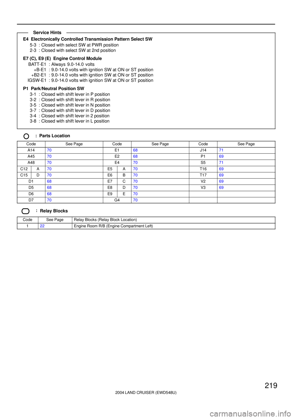
E4 Electronically Controlled Transmission Pattern Select SW
5-3 : Closed with select SW at PWR position
2-3 : Closed with select SW at 2nd position
E7 (C), E9 (E) Engine Control Module
BATT-E1 : Always 9.0-14.0 volts
+B-E1 : 9.0-14.0 volts with ignition SW at ON or ST position
+B2-E1 : 9.0-14.0 volts with ignition SW at ON or ST position
IGSW-E1 : 9.0-14.0 volts with ignition SW at ON or ST position
P1 Park/Neutral Position SW
3-1 : Closed with shift lever in P position
3-2 : Closed with shift lever in R position
3-5 : Closed with shift lever in N position
3-7 : Closed with shift lever in D position
3-4 : Closed with shift lever in 2 position
3-8 : Closed with shift lever in L position
: Parts Location
CodeSee PageCodeSee PageCodeSee Page
A1470E168J1471
A4570E268P169
A4870E470S571
C12A70E5A70T1669
C15D70E6B70T1769
D168E7C70V269
D568E8D70V369
D668E9E70
D770G470
:Relay Blocks
CodeSee PageRelay Blocks (Relay Block Location)
122Engine Room R/B (Engine Compartment Left)
Service Hints
Page 2232 of 3115
2004 LAND CRUISER (EWD548U)
225
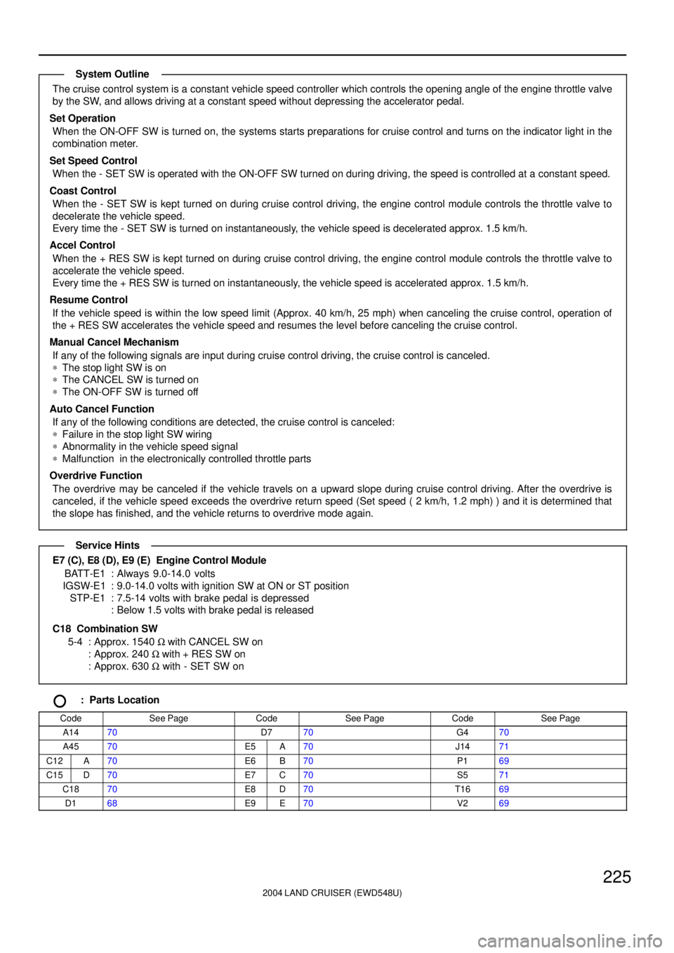
The cruise control system is a constant vehicle speed controller which controls the opening angle of the engine throttle valve
by the SW, and allows driving at a constant speed without depressing the accelerator pedal.
Set Operation
When the ON-OFF SW is turned on, the systems starts preparations for cruise control and turns on the indicator light in the
combination meter.
Set Speed Control
When the - SET SW is operated with the ON-OFF SW turned on during driving, the speed is controlled at a constant speed.
Coast Control
When the - SET SW is kept turned on during cruise control driving, the engine control module controls the throttle valve to
decelerate the vehicle speed.
Every time the - SET SW is turned on instantaneously, the vehicle speed is decelerated approx. 1.5 km/h.
Accel Control
When the + RES SW is kept turned on during cruise control driving, the engine control module controls the throttle valve to
accelerate the vehicle speed.
Every time the + RES SW is turned on instantaneously, the vehicle speed is accelerated approx. 1.5 km/h.
Resume Control
If the vehicle speed is within the low speed limit (Approx. 40 km/h, 25 mph) when canceling the cruise control, operation of
the + RES SW accelerates the vehicle speed and resumes the level before canceling the cruise control.
Manual Cancel Mechanism
If any of the following signals are input during cruise control driving, the cruise control is canceled.
*The stop light SW is on
*The CANCEL SW is turned on
*The ON-OFF SW is turned off
Auto Cancel Function
If any of the following conditions are detected, the cruise control is canceled:
*Failure in the stop light SW wiring
*Abnormality in the vehicle speed signal
*Malfunction in the electronically controlled throttle parts
Overdrive Function
The overdrive may be canceled if the vehicle travels on a upward slope during cruise control driving. After the overdrive is
canceled, if the vehicle speed exceeds the overdrive return speed (Set speed ( 2 km/h, 1.2 mph) ) and it is determined that
the slope has finished, and the vehicle returns to overdrive mode again.
E7 (C), E8 (D), E9 (E) Engine Control Module
BATT-E1 : Always 9.0-14.0 volts
IGSW-E1 : 9.0-14.0 volts with ignition SW at ON or ST position
STP-E1 : 7.5-14 volts with brake pedal is depressed
: Below 1.5 volts with brake pedal is released
C18 Combination SW
5-4 : Approx. 1540 W with CANCEL SW on
: Approx. 240 W with + RES SW on
: Approx. 630 W with - SET SW on
: Parts Location
CodeSee PageCodeSee PageCodeSee Page
A1470D770G470
A4570E5A70J1471
C12A70E6B70P169
C15D70E7C70S571
C1870E8D70T1669
D168E9E70V269
System Outline
Service Hints