1986 TOYOTA LAND CRUISER ignition
[x] Cancel search: ignitionPage 2330 of 3115
2004 LAND CRUISER (EWD548U)
323
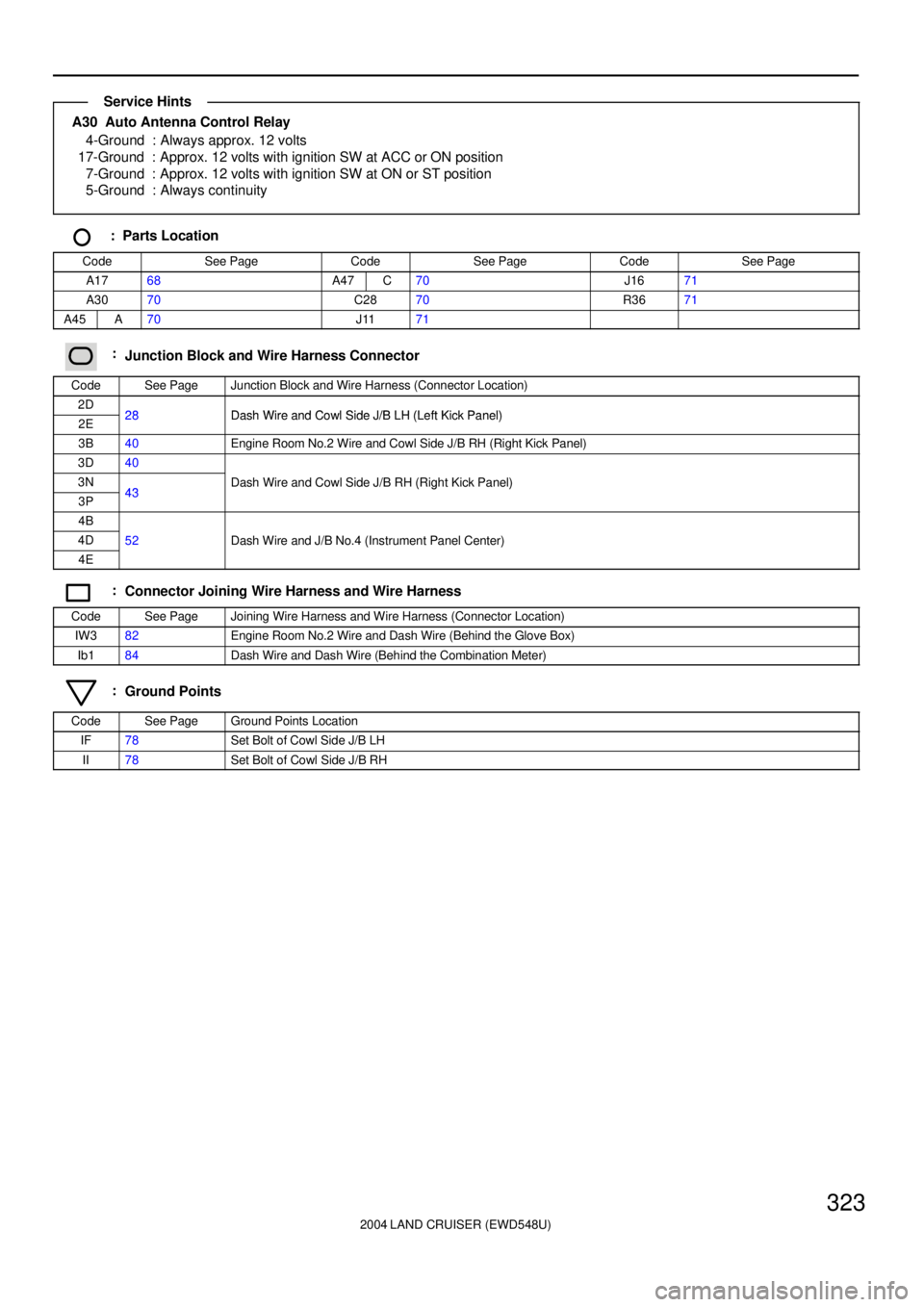
A30 Auto Antenna Control Relay
4-Ground : Always approx. 12 volts
17-Ground : Approx. 12 volts with ignition SW at ACC or ON position
7-Ground : Approx. 12 volts with ignition SW at ON or ST position
5-Ground : Always continuity
: Parts Location
CodeSee PageCodeSee PageCodeSee Page
A1768A47C70J1671
A3070C2870R3671
A45A70J1171
:Junction Block and Wire Harness Connector
CodeSee PageJunction Block and Wire Harness (Connector Location)
2D28Dash Wire and Cowl Side J/B LH (Left Kick Panel)2E28Dash Wire and Cowl Side J/B LH (Left Kick Panel)
3B40Engine Room No.2 Wire and Cowl Side J/B RH (Right Kick Panel)
3D40
3N43Dash Wire and Cowl Side J/B RH (Right Kick Panel)
3P43(g )
4B
4D52Dash Wire and J/B No.4 (Instrument Panel Center)
4E
()
:Connector Joining Wire Harness and Wire Harness
CodeSee PageJoining Wire Harness and Wire Harness (Connector Location)
IW382Engine Room No.2 Wire and Dash Wire (Behind the Glove Box)
Ib184Dash Wire and Dash Wire (Behind the Combination Meter)
:Ground Points
CodeSee PageGround Points Location
IF78Set Bolt of Cowl Side J/B LH
II78Set Bolt of Cowl Side J/B RH
Service Hints
Page 2335 of 3115
2004 LAND CRUISER (EWD548U)
328Radio and Player (w/ Navigation System)
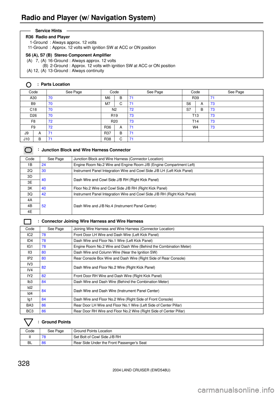
R36 Radio and Player
1-Ground : Always approx. 12 volts
11-Ground : Approx. 12 volts with ignition SW at ACC or ON position
S6 (A), S7 (B) Stereo Component Amplifier
(A) 7, (A) 16-Ground : Always approx. 12 volts
(B) 2-Ground : Approx. 12 volts with ignition SW at ACC or ON position
(A) 12, (A) 13-Ground : Always continuity
: Parts Location
CodeSee PageCodeSee PageCodeSee Page
A3070M6B71R3971
B970M7C71S6A73
C1870N272S7B73
D2670R1973T1373
F872R2073T1473
F972R36A71W473
J9A71R37B71
J10B71R38C71
:Junction Block and Wire Harness Connector
CodeSee PageJunction Block and Wire Harness (Connector Location)
1B24Engine Room No.2 Wire and Engine Room J/B (Engine Compartment Left)
2Q30Instrument Panel Integration Wire and Cowl Side J/B LH (Left Kick Panel)
3D40Dash Wire and Cowl Side J/B RH (Right Kick Panel)3E40Dash Wire and Cowl Side J/B RH (Right Kick Panel)
3K40Floor No.2 Wire and Cowl Side J/B RH (Right Kick Panel)
3Q42Instrument Panel Integration Wire and Cowl Side J/B RH (Right Kick Panel)
4A
4B52Dash Wire and J/B No.4 (Instrument Panel Center)
4E
()
:Connector Joining Wire Harness and Wire Harness
CodeSee PageJoining Wire Harness and Wire Harness (Connector Location)
IC278Front Door LH Wire and Dash Wire (Left Kick Panel)
ID478Dash Wire and Floor No.1 Wire (Left Kick Panel)
IG178Engine Room No.2 Wire and Dash Wire (Behind the Combination Meter)
II380Dash Wire and Column Wire (Near the Ignition SW)
IP280Rear Console Box Wire and Dash Wire (Right Side of Rear Console)
IV382Dash Wire and Floor No 2 Wire (Right Kick Panel)IV482Dash Wire and Floor No.2 Wire (Right Kick Panel)
IY282Front Door RH Wire and Dash Wire (Right Kick Panel)
Ib384Dash Wire and Dash Wire (Behind the Combination Meter)
Id284Dash Wire and Dash Wire (Instrument Panel Center)Id484Dash Wire and Dash Wire (Instrument Panel Center)
Ig184Dash Wire and Floor No.2 Wire (Right Side of Front Console)
BA386Rear Door LH Wire and Floor No.1 Wire (Left Side of Center Pillar)
BC386Rear Door RH Wire and Floor No.2 Wire (Right Side of Center Pillar)
:Ground Points
CodeSee PageGround Points Location
II78Set Bolt of Cowl Side J/B RH
BL86Rear Side Under the Front Passenger's Seat
Service Hints
Page 2341 of 3115
2004 LAND CRUISER (EWD548U)
334Radio and Player (w/o Navigation System)
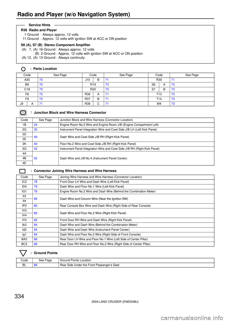
R36 Radio and Player
1-Ground : Always approx. 12 volts
11-Ground : Approx. 12 volts with ignition SW at ACC or ON position
S6 (A), S7 (B) Stereo Component Amplifier
(A) 7, (A) 16-Ground : Always approx. 12 volts
(B) 2-Ground : Approx. 12 volts with ignition SW at ACC or ON position
(A) 12, (A) 13-Ground : Always continuity
: Parts Location
CodeSee PageCodeSee PageCodeSee Page
A3070J10B71R3971
B970R1973S6A73
C1870R2073S7B73
F872R36A71T1373
F972R37B71T1473
J9A71R38C71W473
:Junction Block and Wire Harness Connector
CodeSee PageJunction Block and Wire Harness (Connector Location)
1B24Engine Room No.2 Wire and Engine Room J/B (Engine Compartment Left)
2Q30Instrument Panel Integration Wire and Cowl Side J/B LH (Left Kick Panel)
3D40Dash Wire and Cowl Side J/B RH (Right Kick Panel)3E40Dash Wire and Cowl Side J/B RH (Right Kick Panel)
3K40Floor No.2 Wire and Cowl Side J/B RH (Right Kick Panel)
3Q42Instrument Panel Integration Wire and Cowl Side J/B RH (Right Kick Panel)
4A
4B52Dash Wire and J/B No.4 (Instrument Panel Center)
4E
()
:Connector Joining Wire Harness and Wire Harness
CodeSee PageJoining Wire Harness and Wire Harness (Connector Location)
IC278Front Door LH Wire and Dash Wire (Left Kick Panel)
ID478Dash Wire and Floor No.1 Wire (Left Kick Panel)
IG178Engine Room No.2 Wire and Dash Wire (Behind the Combination Meter)
II380Dash Wire and Column Wire (Near the Ignition SW)II480Dash Wire and Column Wire (Near the Ignition SW)
IP280Rear Console Box Wire and Dash Wire (Right Side of Rear Console)
IV382Dash Wire and Floor No 2 Wire (Right Kick Panel)IV482Dash Wire and Floor No.2 Wire (Right Kick Panel)
IY282Front Door RH Wire and Dash Wire (Right Kick Panel)
Ib384Dash Wire and Dash Wire (Behind the Combination Meter)
Id284Dash Wire and Dash Wire (Instrument Panel Center)
Ig184Dash Wire and Floor No.2 Wire (Right Side of Front Console)
BA386Rear Door LH Wire and Floor No.1 Wire (Left Side of Center Pillar)
BC386Rear Door RH Wire and Floor No.2 Wire (Right Side of Center Pillar)
:Ground Points
CodeSee PageGround Points Location
BL86Rear Side Under the Front Passenger's Seat
Service Hints
Page 2351 of 3115
2004 LAND CRUISER (EWD548U)
344Navigation System, TOYOTA Parking Assist (Rear View Monitor)
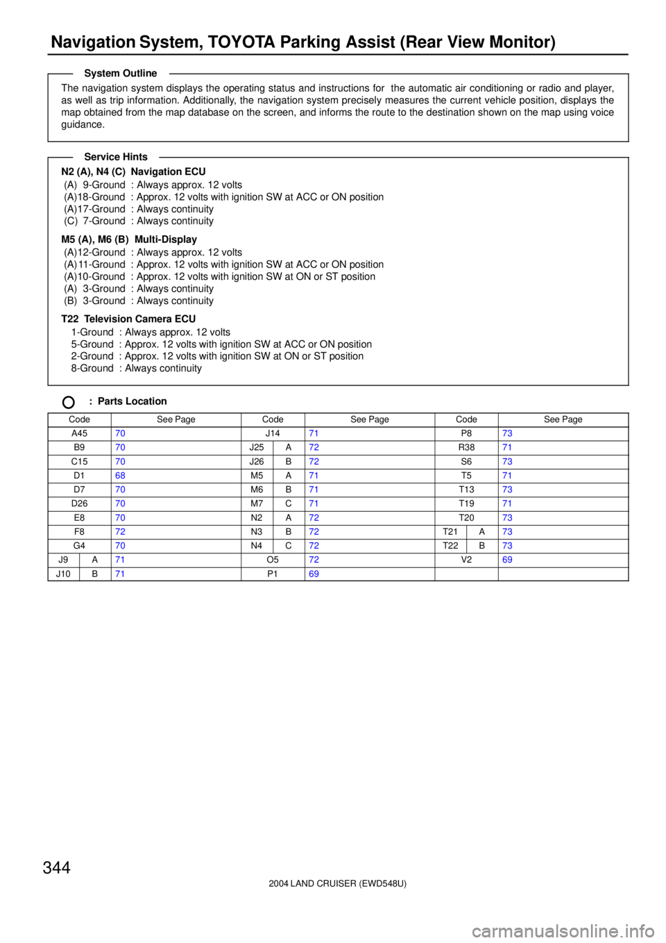
The navigation system displays the operating status and instructions for the automatic air conditioning or radio and player,
as well as trip information. Additionally, the navigation system precisely measures the current vehicle position, displays the
map obtained from the map database on the screen, and informs the route to the destination shown on the map using voice
guidance.
N2 (A), N4 (C) Navigation ECU
(A) 9-Ground : Always approx. 12 volts
(A)18-Ground : Approx. 12 volts with ignition SW at ACC or ON position
(A)17-Ground : Always continuity
(C) 7-Ground : Always continuity
M5 (A), M6 (B) Multi-Display
(A)12-Ground : Always approx. 12 volts
(A) 11-Ground : Approx. 12 volts with ignition SW at ACC or ON position
(A)10-Ground : Approx. 12 volts with ignition SW at ON or ST position
(A) 3-Ground : Always continuity
(B) 3-Ground : Always continuity
T22 Television Camera ECU
1-Ground : Always approx. 12 volts
5-Ground : Approx. 12 volts with ignition SW at ACC or ON position
2-Ground : Approx. 12 volts with ignition SW at ON or ST position
8-Ground : Always continuity
: Parts Location
CodeSee PageCodeSee PageCodeSee Page
A4570J1471P873
B970J25A72R3871
C1570J26B72S673
D168M5A71T571
D770M6B71T1373
D2670M7C71T1971
E870N2A72T2073
F872N3B72T21A73
G470N4C72T22B73
J9A71O572V269
J10B71P169
System Outline
Service Hints
Page 2356 of 3115
2004 LAND CRUISER (EWD548U)
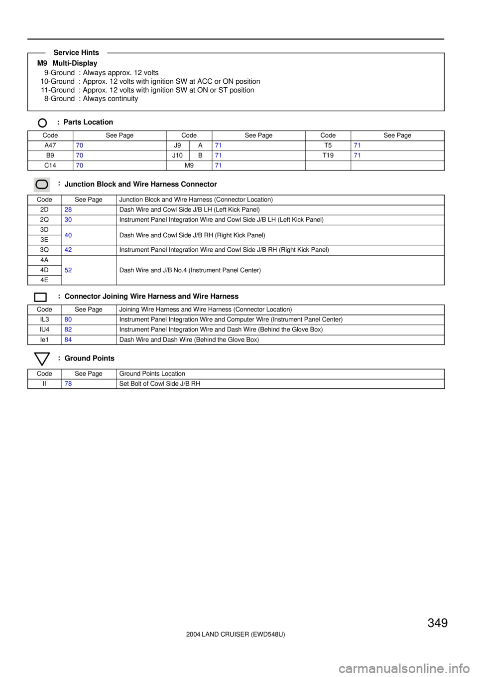
349
M9 Multi-Display
9-Ground : Always approx. 12 volts
10-Ground : Approx. 12 volts with ignition SW at ACC or ON position
11-Ground : Approx. 12 volts with ignition SW at ON or ST position
8-Ground : Always continuity
: Parts Location
CodeSee PageCodeSee PageCodeSee Page
A4770J9A71T571
B970J10B71T1971
C1470M971
:Junction Block and Wire Harness Connector
CodeSee PageJunction Block and Wire Harness (Connector Location)
2D28Dash Wire and Cowl Side J/B LH (Left Kick Panel)
2Q30Instrument Panel Integration Wire and Cowl Side J/B LH (Left Kick Panel)
3D40Dash Wire and Cowl Side J/B RH (Right Kick Panel)3E40Dash Wire and Cowl Side J/B RH (Right Kick Panel)
3Q42Instrument Panel Integration Wire and Cowl Side J/B RH (Right Kick Panel)
4A
4D52Dash Wire and J/B No.4 (Instrument Panel Center)
4E
()
:Connector Joining Wire Harness and Wire Harness
CodeSee PageJoining Wire Harness and Wire Harness (Connector Location)
IL380Instrument Panel Integration Wire and Computer Wire (Instrument Panel Center)
IU482Instrument Panel Integration Wire and Dash Wire (Behind the Glove Box)
Ie184Dash Wire and Dash Wire (Behind the Glove Box)
:Ground Points
CodeSee PageGround Points Location
II78Set Bolt of Cowl Side J/B RH
Service Hints
Page 2362 of 3115
2004 LAND CRUISER (EWD548U)
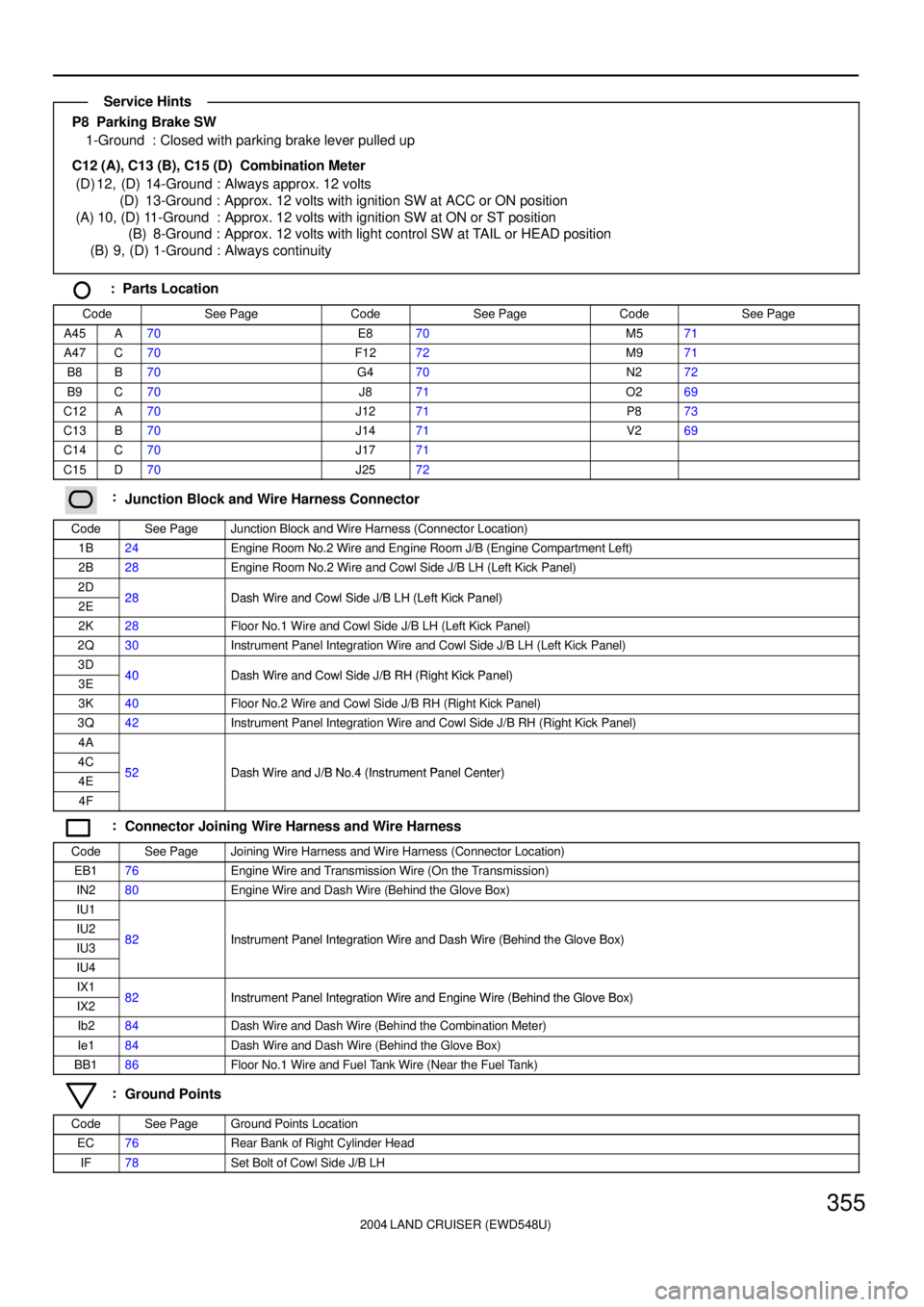
355
P8 Parking Brake SW
1-Ground : Closed with parking brake lever pulled up
C12 (A), C13 (B), C15 (D) Combination Meter
(D) 12, (D) 14-Ground : Always approx. 12 volts
(D) 13-Ground : Approx. 12 volts with ignition SW at ACC or ON position
(A) 10, (D) 11-Ground : Approx. 12 volts with ignition SW at ON or ST position
(B) 8-Ground : Approx. 12 volts with light control SW at TAIL or HEAD position
(B) 9, (D) 1-Ground : Always continuity
: Parts Location
CodeSee PageCodeSee PageCodeSee Page
A45A70E870M571
A47C70F1272M971
B8B70G470N272
B9C70J871O269
C12A70J1271P873
C13B70J1471V269
C14C70J1771
C15D70J2572
:Junction Block and Wire Harness Connector
CodeSee PageJunction Block and Wire Harness (Connector Location)
1B24Engine Room No.2 Wire and Engine Room J/B (Engine Compartment Left)
2B28Engine Room No.2 Wire and Cowl Side J/B LH (Left Kick Panel)
2D28Dash Wire and Cowl Side J/B LH (Left Kick Panel)2E28Dash Wire and Cowl Side J/B LH (Left Kick Panel)
2K28Floor No.1 Wire and Cowl Side J/B LH (Left Kick Panel)
2Q30Instrument Panel Integration Wire and Cowl Side J/B LH (Left Kick Panel)
3D40Dash Wire and Cowl Side J/B RH (Right Kick Panel)3E40Dash Wire and Cowl Side J/B RH (Right Kick Panel)
3K40Floor No.2 Wire and Cowl Side J/B RH (Right Kick Panel)
3Q42Instrument Panel Integration Wire and Cowl Side J/B RH (Right Kick Panel)
4A
4C52Dash Wire and J/B No 4 (Instrument Panel Center)4E52Dash Wire and J/B No.4 (Instrument Panel Center)
4F
:Connector Joining Wire Harness and Wire Harness
CodeSee PageJoining Wire Harness and Wire Harness (Connector Location)
EB176Engine Wire and Transmission Wire (On the Transmission)
IN280Engine Wire and Dash Wire (Behind the Glove Box)
IU1
IU282Instrument Panel Integration Wire and Dash Wire (Behind the Glove Box)IU382Instrument Panel Integration Wire and Dash Wire (Behind the Glove Box)
IU4
IX182Instrument Panel Integration Wire and Engine Wire (Behind the Glove Box)IX282Instrument Panel Integration Wire and Engine Wire (Behind the Glove Box)
Ib284Dash Wire and Dash Wire (Behind the Combination Meter)
Ie184Dash Wire and Dash Wire (Behind the Glove Box)
BB186Floor No.1 Wire and Fuel Tank Wire (Near the Fuel Tank)
:Ground Points
CodeSee PageGround Points Location
EC76Rear Bank of Right Cylinder Head
IF78Set Bolt of Cowl Side J/B LH
Service Hints
Page 2369 of 3115
2004 LAND CRUISER (EWD548U)
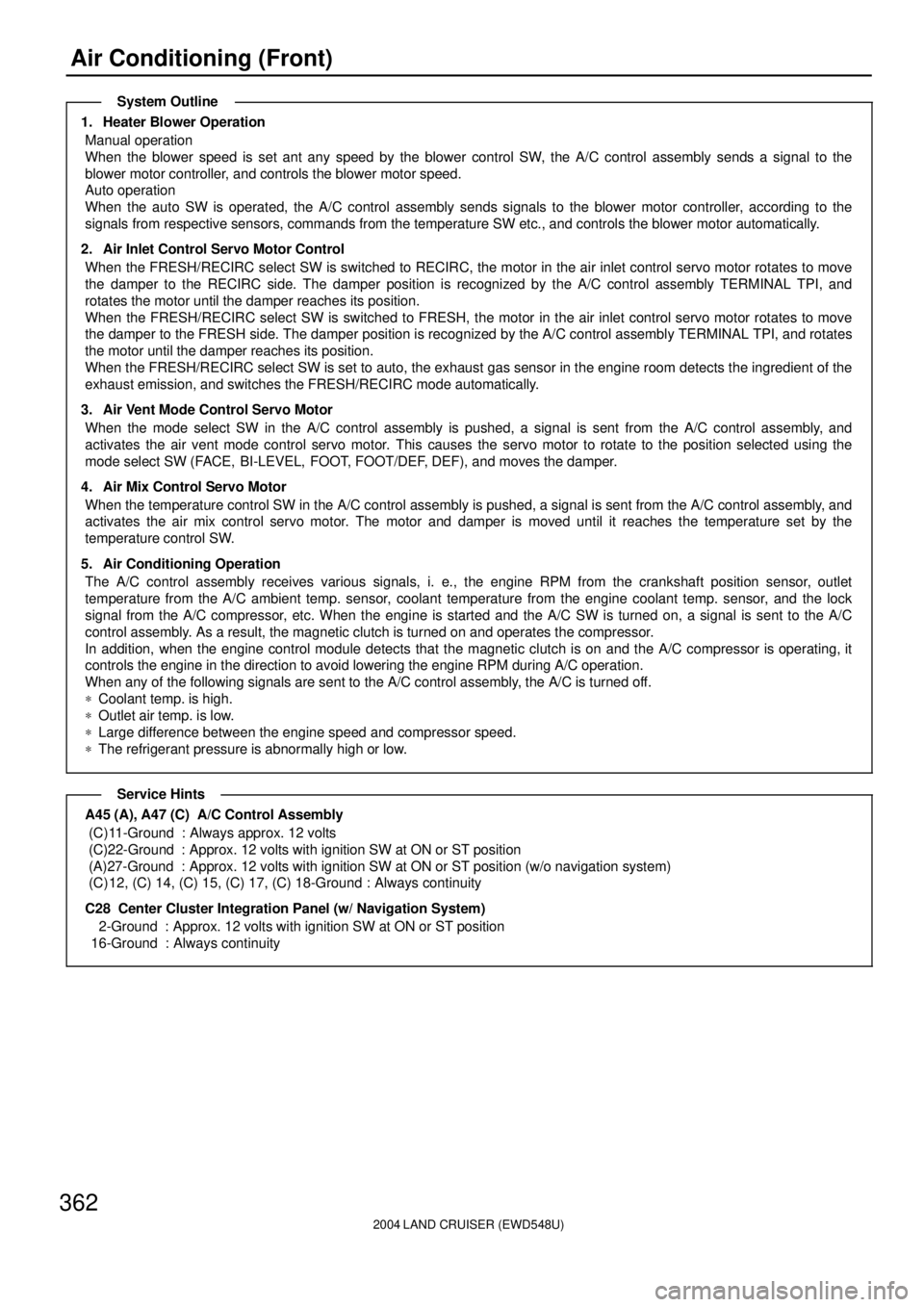
362Air Conditioning (Front)
1. Heater Blower Operation
Manual operation
When the blower speed is set ant any speed by the blower control SW, the A/C control assembly sends a signal to the
blower motor controller, and controls the blower motor speed.
Auto operation
When the auto SW is operated, the A/C control assembly sends signals to the blower motor controller, according to the
signals from respective sensors, commands from the temperature SW etc., and controls the blower motor automatically.
2. Air Inlet Control Servo Motor Control
When the FRESH/RECIRC select SW is switched to RECIRC, the motor in the air inlet control servo motor rotates to move
the damper to the RECIRC side. The damper position is recognized by the A/C control assembly TERMINAL TPI, and
rotates the motor until the damper reaches its position.
When the FRESH/RECIRC select SW is switched to FRESH, the motor in the air inlet control servo motor rotates to move
the damper to the FRESH side. The damper position is recognized by the A/C control assembly TERMINAL TPI, and rotates
the motor until the damper reaches its position.
When the FRESH/RECIRC select SW is set to auto, the exhaust gas sensor in the engine room detects the ingredient of the
exhaust emission, and switches the FRESH/RECIRC mode automatically.
3. Air Vent Mode Control Servo Motor
When the mode select SW in the A/C control assembly is pushed, a signal is sent from the A/C control assembly, and
activates the air vent mode control servo motor. This causes the servo motor to rotate to the position selected using the
mode select SW (FACE, BI-LEVEL, FOOT, FOOT/DEF, DEF), and moves the damper.
4. Air Mix Control Servo Motor
When the temperature control SW in the A/C control assembly is pushed, a signal is sent from the A/C control assembly, and
activates the air mix control servo motor. The motor and damper is moved until it reaches the temperature set by the
temperature control SW.
5. Air Conditioning Operation
The A/C control assembly receives various signals, i. e., the engine RPM from the crankshaft position sensor, outlet
temperature from the A/C ambient temp. sensor, coolant temperature from the engine coolant temp. sensor, and the lock
signal from the A/C compressor, etc. When the engine is started and the A/C SW is turned on, a signal is sent to the A/C
control assembly. As a result, the magnetic clutch is turned on and operates the compressor.
In addition, when the engine control module detects that the magnetic clutch is on and the A/C compressor is operating, it
controls the engine in the direction to avoid lowering the engine RPM during A/C operation.
When any of the following signals are sent to the A/C control assembly, the A/C is turned off.
*Coolant temp. is high.
*Outlet air temp. is low.
*Large difference between the engine speed and compressor speed.
*The refrigerant pressure is abnormally high or low.
A45 (A), A47 (C) A/C Control Assembly
(C)11-Ground : Always approx. 12 volts
(C)22-Ground : Approx. 12 volts with ignition SW at ON or ST position
(A)27-Ground : Approx. 12 volts with ignition SW at ON or ST position (w/o navigation system)
(C) 12, (C) 14, (C) 15, (C) 17, (C) 18-Ground : Always continuity
C28 Center Cluster Integration Panel (w/ Navigation System)
2-Ground : Approx. 12 volts with ignition SW at ON or ST position
16-Ground : Always continuity
System Outline
Service Hints
Page 2373 of 3115
2004 LAND CRUISER (EWD548U)
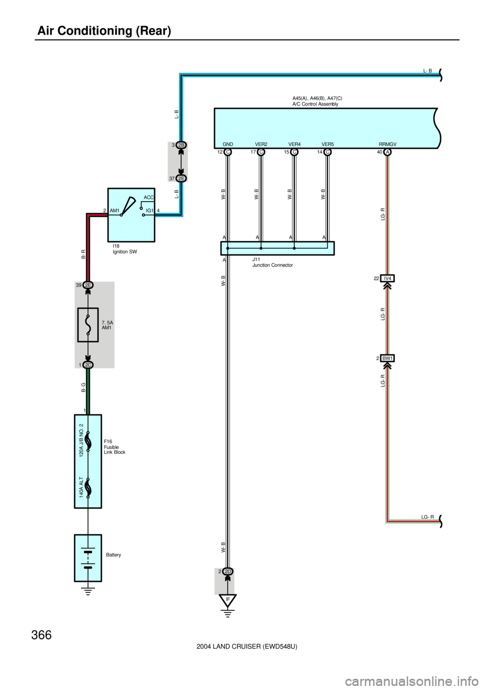
366Air Conditioning (Rear)
A45(
A)
, A46(
B)
, A47(
C)
C 12GND
IF A AVER2
17 C
AVER4
15 C
AVER5
14 C
A
W- B
W- B
W- B
W- B
J11
2D 2
W- B W- B
A 40RRMGV
IV4 22
LG- R LG- R
BW1 2
140A ALT 120A J/B NO. 2
F1 6
B- G
2C 17. 5A
AM1 2E 39
B- R
24AM1ACC
IG12E 37
L- B
2B 3
LG- R
LG- RL- B
L- B
I18
Battery 1Ignition SWA/C Control Assembly
Junction Connector
Fusib le
Link Block