Page 1793 of 3115
EM-2
- ENGINE MECHANICALCO/HC
1575 Author�: Date�:
2004 LAND CRUISER (RM1071U)
6. TROUBLESHOOTING
HINT:
If the CO/HC concentration does not comply with the regula-
tions, perform troubleshooting in the order given below.
See the table below for possible causes, and then inspect and
correct the applicable causes if necessary.
COHCProblemsCauses
NormalHighRough idle1. Faulty ignitions:
� Incorrect timing
� Fouled, shorted or improperly gapped plugs
2. Incorrect valve clearance
3. Leaky intake and exhaust valves
4. Leaky cylinders
LowHighRough idle
(fluctuating HC reading)1. Vacuum leaks:
� PCV hoses
� Intake manifold
� Throttle body
� Brake booster line
2. Lean mixture causing misfire
HighHighRough idle
(Black smoke from exhaust)1. Restricted air filter
2.Faulty SFI systems:
� Faulty pressure regulator
� Defective ECT sensor
� Faulty ECM
� Faulty injectors
� Faulty throttle position sensor
� Faulty MAF meter
Page 1827 of 3115
A19470
EVAP Hose EVAP PipeRear Water
Bypass Joint
Engine Wire
� Gasket
Injection Connector
Fuel Inlet Hose
Ignition Coil
Connector
Ignition Coil Throttle Control
Connector
Water Bypass
Hose
ECT
Sensor Connector
Front Water
Bypass Joint
Water Inlet and Inlet
Housing AssemblyWater Bypass Hose Water
Sender Gauge
LH No.1 Timing Belt Rear Plate
� Non-reusable partEngine WireEngine Wire
� Gasket
� O-Ring
RH No.1 Timing
Belt Rear PlateEVAP Hose
Engine Wire
� GasketHeater
Hose V-Bank Cover
Bracket
V-Bank Cover
BracketPS Hose
VSV Connector
for EVAP Fuel Return Hose
V-Bank Cover
Bracket
Engine Wire
EVAP VSV Hose
Heater Hose
Wire Bracket
- ENGINE MECHANICALCYLINDER HEAD
EM-31
1604 Author�: Date�:
2004 LAND CRUISER (RM1071U)
Page 1853 of 3115

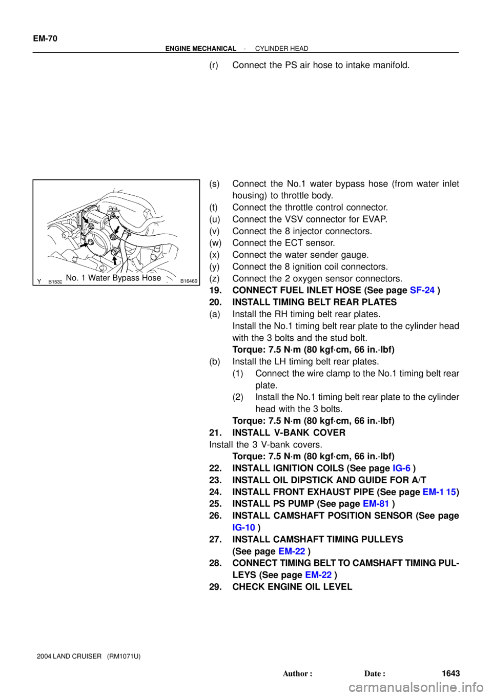
B15320B16469No. 1 Water Bypass Hose
EM-70
- ENGINE MECHANICALCYLINDER HEAD
1643 Author�: Date�:
2004 LAND CRUISER (RM1071U)
(r) Connect the PS air hose to intake manifold.
(s) Connect the No.1 water bypass hose (from water inlet
housing) to throttle body.
(t) Connect the throttle control connector.
(u) Connect the VSV connector for EVAP.
(v) Connect the 8 injector connectors.
(w) Connect the ECT sensor.
(x) Connect the water sender gauge.
(y) Connect the 8 ignition coil connectors.
(z) Connect the 2 oxygen sensor connectors.
19. CONNECT FUEL INLET HOSE (See page SF-24)
20. INSTALL TIMING BELT REAR PLATES
(a) Install the RH timing belt rear plates.
Install the No.1 timing belt rear plate to the cylinder head
with the 3 bolts and the stud bolt.
Torque: 7.5 N´m (80 kgf´cm, 66 in.´lbf)
(b) Install the LH timing belt rear plates.
(1) Connect the wire clamp to the No.1 timing belt rear
plate.
(2) Install the No.1 timing belt rear plate to the cylinder
head with the 3 bolts.
Torque: 7.5 N´m (80 kgf´cm, 66 in.´lbf)
21. INSTALL V-BANK COVER
Install the 3 V-bank covers.
Torque: 7.5 N´m (80 kgf´cm, 66 in.´lbf)
22. INSTALL IGNITION COILS (See page IG-6)
23. INSTALL OIL DIPSTICK AND GUIDE FOR A/T
24. INSTALL FRONT EXHAUST PIPE (See page EM-1 15)
25. INSTALL PS PUMP (See page EM-81)
26. INSTALL CAMSHAFT POSITION SENSOR (See page
IG-10)
27. INSTALL CAMSHAFT TIMING PULLEYS
(See page EM-22)
28. CONNECT TIMING BELT TO CAMSHAFT TIMING PUL-
LEYS (See page EM-22)
29. CHECK ENGINE OIL LEVEL
Page 1856 of 3115

EM1V8-01
A02844
- ENGINE MECHANICALCYLINDER HEAD
EM-35
1608 Author�: Date�:
2004 LAND CRUISER (RM1071U)
REMOVAL
1. DRAIN ENGINE COOLANT
2. REMOVE V-BANK COVER
Remove the V-bank covers.
3. DISCONNECT TIMING BELT FROM CAMSHAFT TIM-
ING PULLEYS (See page EM-15)
4. REMOVE CAMSHAFT TIMING PULLEYS (See page
EM-15)
5. REMOVE CAMSHAFT POSITION SENSOR (See page
IG-9)
6. DISCONNECT PS PUMP FROM ENGINE
(See page EM-77)
7. REMOVE FRONT EXHAUST PIPE (See page EM-1 15)
8. REMOVE OIL DIPSTICK AND GUIDE FOR A/T
9. REMOVE IGNITION COILS (See page IG-6)
10. REMOVE TIMING BELT REAR PLATES
(1) Remove the 3 bolts, the stud bolt, and the RH No.1
timing belt rear plates.
(2) Disconnect the wire clamp from the LH timing belt
rear plate.
(3) Remove the 3 bolts, the stud bolt, the LH No.1 and
the timing belt rear plates.
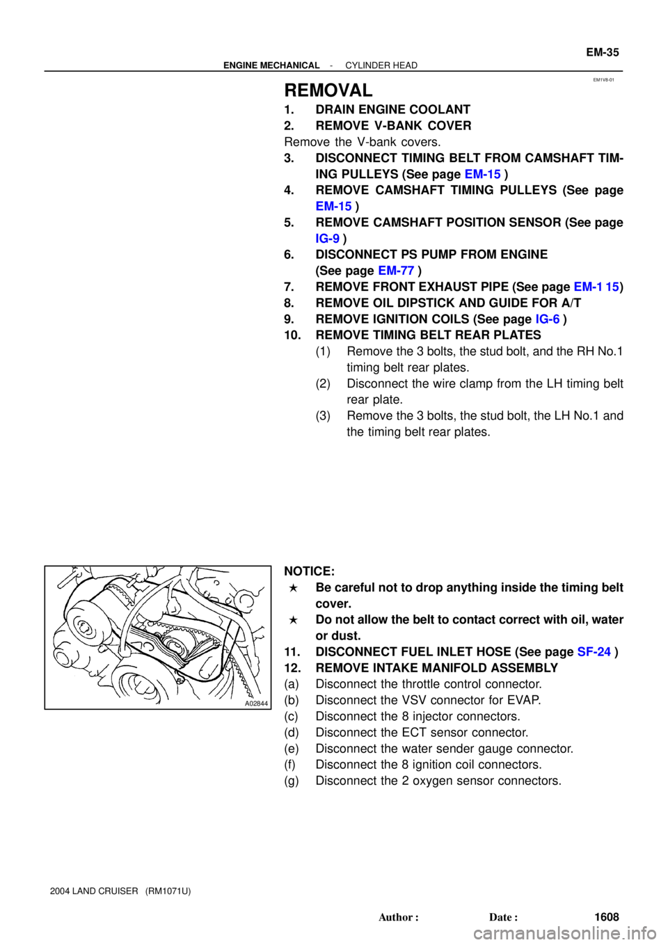
NOTICE:
�Be careful not to drop anything inside the timing belt
cover.
�Do not allow the belt to contact correct with oil, water
or dust.
11. DISCONNECT FUEL INLET HOSE (See page SF-24)
12. REMOVE INTAKE MANIFOLD ASSEMBLY
(a) Disconnect the throttle control connector.
(b) Disconnect the VSV connector for EVAP.
(c) Disconnect the 8 injector connectors.
(d) Disconnect the ECT sensor connector.
(e) Disconnect the water sender gauge connector.
(f) Disconnect the 8 ignition coil connectors.
(g) Disconnect the 2 oxygen sensor connectors.
Page 1883 of 3115
EM0KU-10
- ENGINE MECHANICALIDLE SPEED
EM-1 1
1584 Author�: Date�:
2004 LAND CRUISER (RM1071U)
IDLE SPEED
INSPECTION
1. INITIAL CONDITIONS
(a) Engine is at normal operating temperature
(b) Air cleaner is installed
(c) All pipes and hoses of air induction systems are connected
(d) All accessories are switched OFF
(e) All vacuum lines are properly connected
HINT:
All vacuum hoses should be properly connected.
(f) SFI system wiring connectors are fully plugged
(g) Ignition timing is set correctly
(h) Transmission is in neutral position
(i) Air conditioning switches are OFF
2. CONNECT TOYOTA HAND-HELD TESTER OR OBD II SCAN TOOL
(See page EM-9)
3. INSPECT IDLE SPEED
(a) Race the engine speed at 2,500 rpm for approx. 90 seconds.
(b) Check the idle speed.
Idle speed: 700 ± 50 rpm
If the idle speed is not as specified, check the air intake system.
4. DISCONNECT TOYOTA HAND-HELD TESTER OR OBD II SCAN TOOL
Page 1884 of 3115

EM0KT-10
A07061
TOYOTA Hand-Held Tester
DLC3
A05511
A05512
SSTTC
E1
A04459
- ENGINE MECHANICALIGNITION TIMING
EM-9
1582 Author�: Date�:
2004 LAND CRUISER (RM1071U)
IGNITION TIMING
INSPECTION
1. REMOVE BATTERY CLAMP COVER
2. REMOVE INTAKE AIR CONNECTOR
3. REMOVE V-BANK COVER
4. WARM UP ENGINE
Allow the engine to warm up to the normal operating tempera-
ture.
5. CONNECT TOYOTA HAND-HELD TESTER OR OBD II
SCAN TOOL
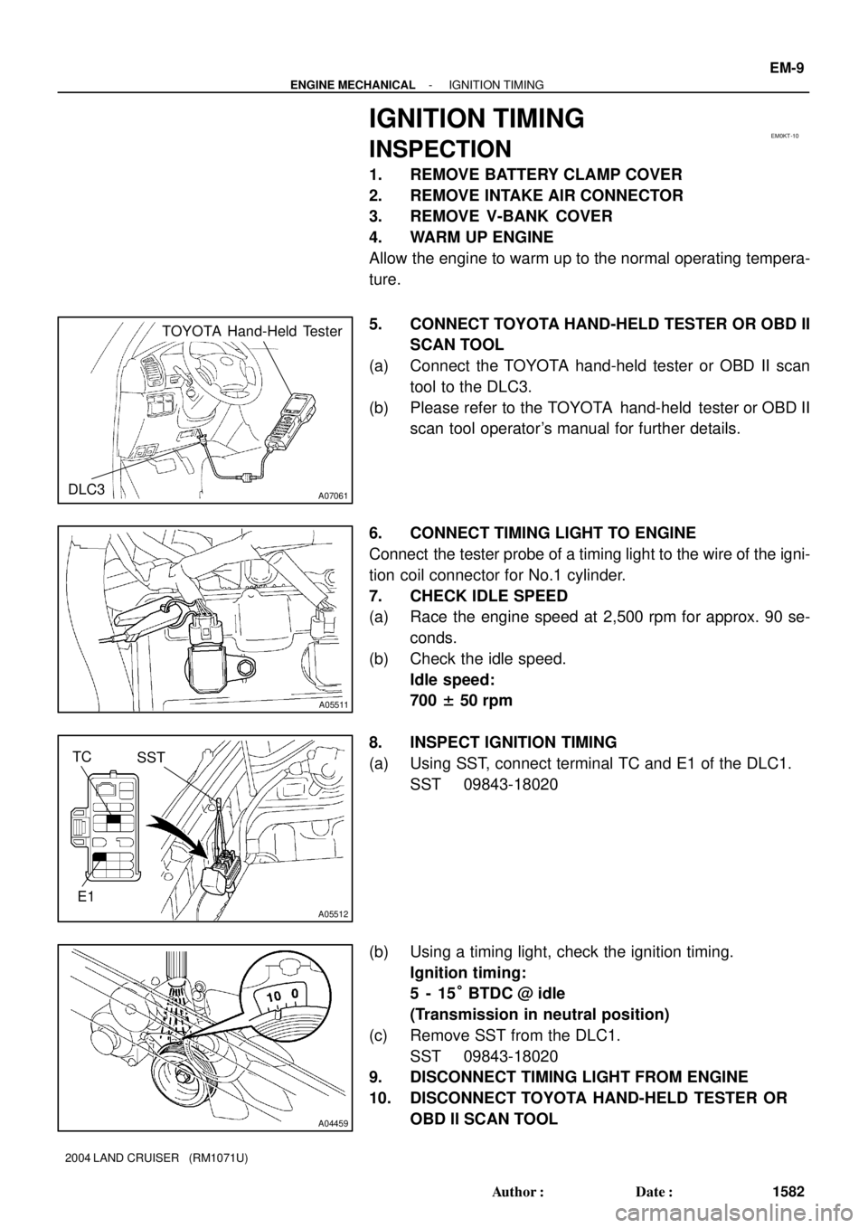
(a) Connect the TOYOTA hand-held tester or OBD II scan
tool to the DLC3.
(b) Please refer to the TOYOTA hand-held tester or OBD II
scan tool operator's manual for further details.
6. CONNECT TIMING LIGHT TO ENGINE
Connect the tester probe of a timing light to the wire of the igni-
tion coil connector for No.1 cylinder.
7. CHECK IDLE SPEED
(a) Race the engine speed at 2,500 rpm for approx. 90 se-
conds.
(b) Check the idle speed.
Idle speed:
700 ± 50 rpm
8. INSPECT IGNITION TIMING
(a) Using SST, connect terminal TC and E1 of the DLC1.
SST 09843-18020
(b) Using a timing light, check the ignition timing.
Ignition timing:
5 - 15° BTDC @ idle
(Transmission in neutral position)
(c) Remove SST from the DLC1.
SST 09843-18020
9. DISCONNECT TIMING LIGHT FROM ENGINE
10. DISCONNECT TOYOTA HAND-HELD TESTER OR
OBD II SCAN TOOL
Page 1885 of 3115
EM-10
- ENGINE MECHANICALIGNITION TIMING
1583 Author�: Date�:
2004 LAND CRUISER (RM1071U)
11. REINSTALL V-BANK COVER
12. REINSTALL INTAKE AIR CONNECTOR
13. REINSTALL BATTERY CLAMP COVER
Page 1902 of 3115

EM0KS-08
A04324
A04325
EM-4
- ENGINE MECHANICALVALVE CLEARANCE
1577 Author�: Date�:
2004 LAND CRUISER (RM1071U)
VALVE CLEARANCE
INSPECTION
HINT:
Inspect and adjust the valve clearance when the engine is cold.
1. DRAIN ENGINE COOLANT
2. REMOVE BATTERY CLAMP COVER
3. REMOVE V-BANK COVER
4. REMOVE AIR CLEANER AND INTAKE AIR CONNEC-
TOR ASSEMBLY
5. REMOVE NO.3 TIMING BELT COVERS
(See page EM-15)
6. REMOVE IGNITION COILS (See page IG-6)
7. REMOVE RH CYLINDER HEAD COVER
Remove the 9 bolts, the 9 seal washers and the cylinder head
cover.
8. REMOVE LH CYLINDER HEAD COVER
(a) Remove the oil dipstick for the transmission.
(b) Disconnect the PCV hose.
(c) Disconnect the engine wire clamp from the wire bracket
on the cylinder head cover.
(d) Remove the 9 bolts, the 9 seal washers and the cylinder
head cover.
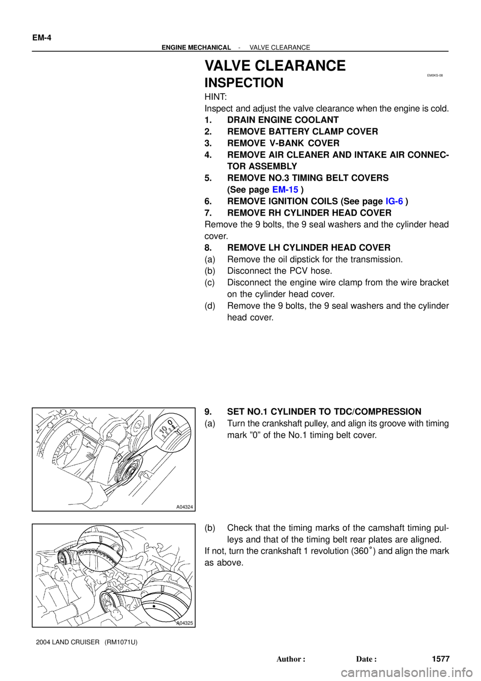
9. SET NO.1 CYLINDER TO TDC/COMPRESSION
(a) Turn the crankshaft pulley, and align its groove with timing
mark º0º of the No.1 timing belt cover.
(b) Check that the timing marks of the camshaft timing pul-
leys and that of the timing belt rear plates are aligned.
If not, turn the crankshaft 1 revolution (360°) and align the mark
as above.