1986 TOYOTA LAND CRUISER ignition
[x] Cancel search: ignitionPage 1958 of 3115
2004 LAND CRUISER (EWD548U)
19 E
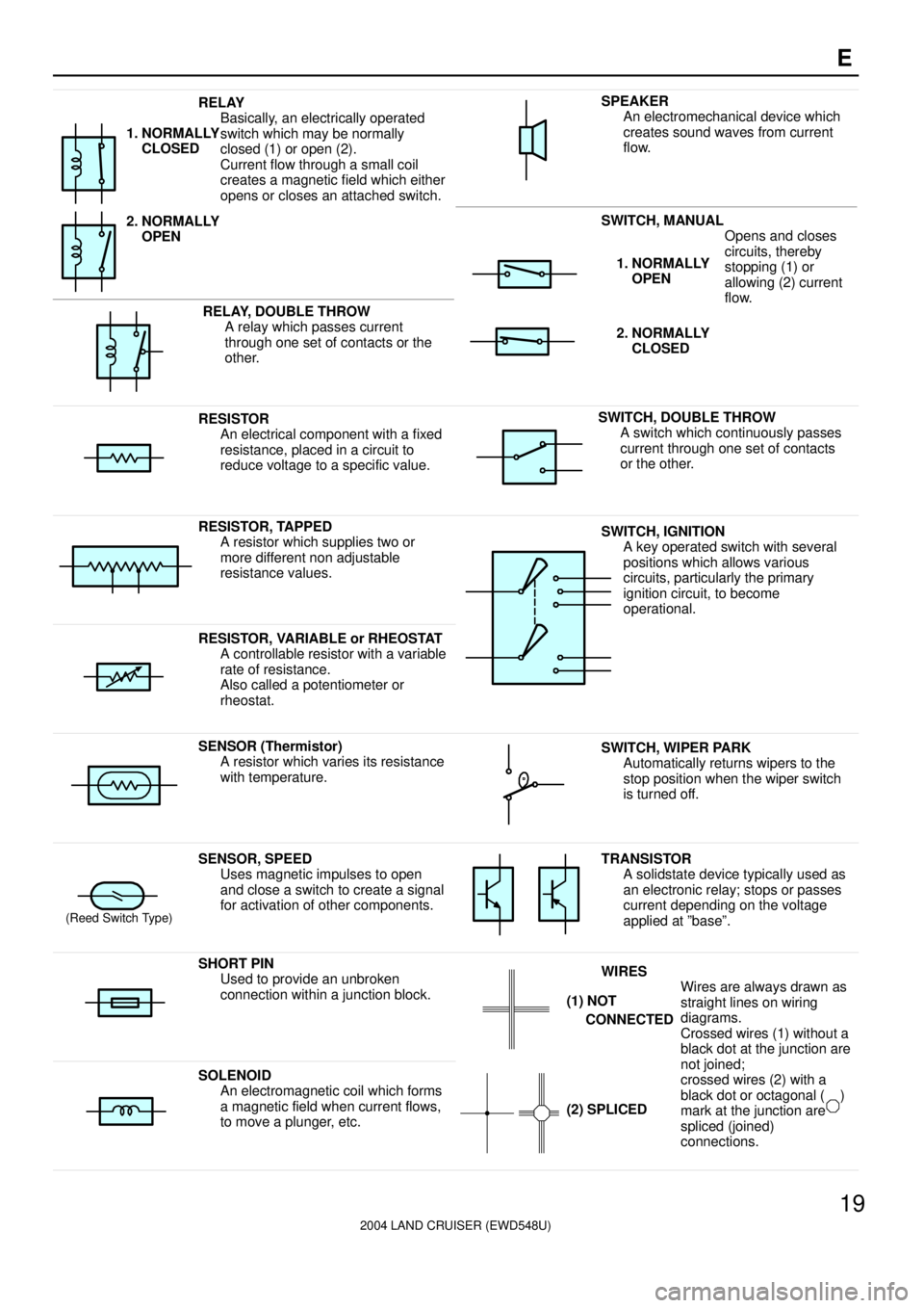
RELAY
Basically, an electrically operated
switch which may be normally
closed (1) or open (2).
Current flow through a small coil
creates a magnetic field which either
opens or closes an attached switch.
1. NORMALLY
CLOSED
2. NORMALLY
OPEN
SWITCH, MANUAL
Opens and closes
iitth b
SPEAKER
An electromechanical device which
creates sound waves from current
flow.
RELAY, DOUBLE THROW
A relay which passes current
through one set of contacts or the
other.
circuits, thereby
stopping (1) or
allowing (2) current
flow.1. NORMALLY
OPEN
2. NORMALLY
CLOSED
RESISTOR
An electrical component with a fixed
resistance, placed in a circuit to
reduce voltage to a specific value.SWITCH, DOUBLE THROW
A switch which continuously passes
current through one set of contacts
or the other.
RESISTOR, TAPPED
A resistor which supplies two or
more different non adjustable
resistance values.SWITCH, IGNITION
A key operated switch with several
positions which allows various
circuits, particularly the primary
ignition circuit, to become
operational.
RESISTOR, VARIABLE or RHEOSTAT
A controllable resistor with a variable
rate of resistance.
Also called a potentiometer or
rheostat.
SENSOR (Thermistor)
A resistor which varies its resistance
with temperature.SWITCH, WIPER PARK
Automatically returns wipers to the
stop position when the wiper switch
is turned off.
(Reed Switch Type)
SENSOR, SPEED
Uses magnetic impulses to open
and close a switch to create a signal
for activation of other components.TRANSISTOR
A solidstate device typically used as
an electronic relay; stops or passes
current depending on the voltage
applied at ºbaseº.
SHORT PIN
Used to provide an unbroken
connection within a junction block.WIRES
Wires are always drawn as
straight lines on wiring
diagrams.
Crossed wires (1) without a
black dot at the junction are
tj i d
(1) NOT
CONNECTED
SOLENOID
An electromagnetic coil which forms
a magnetic field when current flows,
to move a plunger, etc.
j
not joined;
crossed wires (2) with a
black dot or octagonal ( )
mark at the junction are
spliced (joined)
connections.
(2) SPLICED
Page 1963 of 3115
2004 LAND CRUISER (EWD548U)
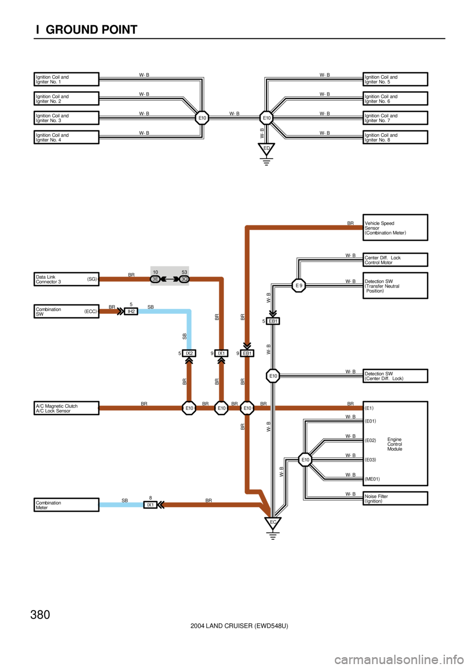
380I GROUND POINT
5
Engine
Control
Module E 9
ECE10 5
IH2
IX18E10 E10 Ignition Coil and
Igniter No. 1
Ignition Coil and
Igniter No. 2
Ignition Coil and
Igniter No. 3
Ignition Coil and
Igniter No. 4
Data Link
Connector 3
Combination
SWIgnition Coil and
Igniter No. 5
Ignition Coil and
Igniter No. 6
Ignition Coil and
Igniter No. 7
Ignition Coil and
Igniter No. 8
Center Diff. Lock
Control Motor
Detection SW
(
Transfer Neutral
Position)
EB1
Detection SW
(
Center Diff. Lock)
(
E01)
(
E02)
(
E03)
(
ME01)
Combination
MeterED
IX2 5
E10W- B
W- B
W- B
W- B
W- B
W- B
W- B BR SB BR
BR
SB
W- BBR SB
BR
W- B
W- B
W- B
W- B
W- BW- BW- B
W- B
W- B
W- B
W- B
BR
E10
E10Vehicle Speed
Sensor
(
Combination Meter) BR
BR BR
BR
(
SG)
A/C Magnetic Clutch
A/C Lock SensorEB1 9
W- BIX1 9 3Q53
3E10
W- B
W- B
Noise Filter
(
Ignition) (
ECC)
BR
(
E1)
E10 BR BR
BR
BR
Page 1965 of 3115
2004 LAND CRUISER (EWD548U)
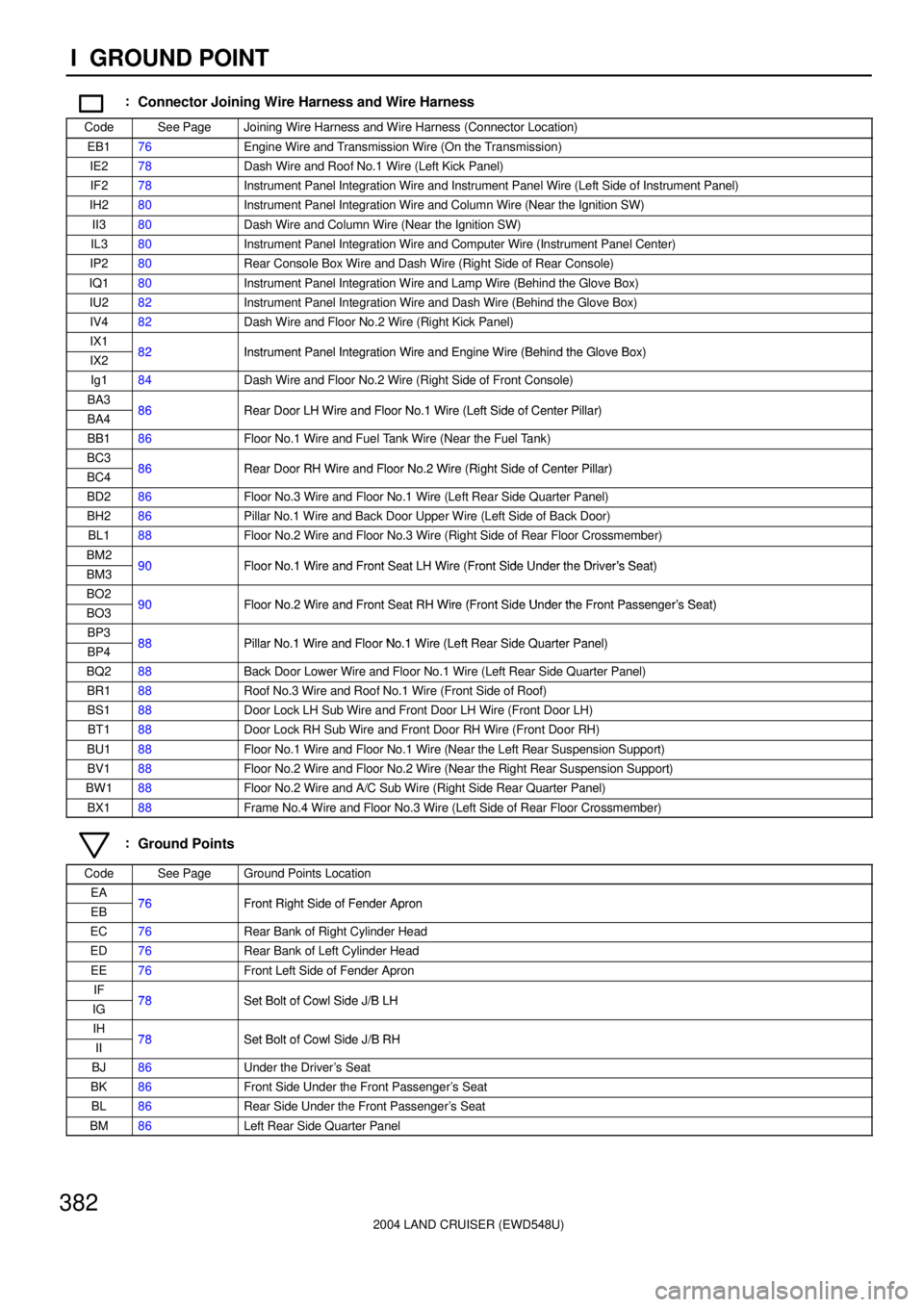
382I GROUND POINT
:Connector Joining Wire Harness and Wire Harness
CodeSee PageJoining Wire Harness and Wire Harness (Connector Location)
EB176Engine Wire and Transmission Wire (On the Transmission)
IE278Dash Wire and Roof No.1 Wire (Left Kick Panel)
IF278Instrument Panel Integration Wire and Instrument Panel Wire (Left Side of Instrument Panel)
IH280Instrument Panel Integration Wire and Column Wire (Near the Ignition SW)
II380Dash Wire and Column Wire (Near the Ignition SW)
IL380Instrument Panel Integration Wire and Computer Wire (Instrument Panel Center)
IP280Rear Console Box Wire and Dash Wire (Right Side of Rear Console)
IQ180Instrument Panel Integration Wire and Lamp Wire (Behind the Glove Box)
IU282Instrument Panel Integration Wire and Dash Wire (Behind the Glove Box)
IV482Dash Wire and Floor No.2 Wire (Right Kick Panel)
IX182Instrument Panel Integration Wire and Engine Wire (Behind the Glove Box)IX282Instrument Panel Integration Wire and Engine Wire (Behind the Glove Box)
Ig184Dash Wire and Floor No.2 Wire (Right Side of Front Console)
BA386Rear Door LH Wire and Floor No 1 Wire (Left Side of Center Pillar)BA486Rear Door LH Wire and Floor No.1 Wire (Left Side of Center Pillar)
BB186Floor No.1 Wire and Fuel Tank Wire (Near the Fuel Tank)
BC386Rear Door RH Wire and Floor No 2 Wire (Right Side of Center Pillar)BC486Rear Door RH Wire and Floor No.2 Wire (Right Side of Center Pillar)
BD286Floor No.3 Wire and Floor No.1 Wire (Left Rear Side Quarter Panel)
BH286Pillar No.1 Wire and Back Door Upper Wire (Left Side of Back Door)
BL188Floor No.2 Wire and Floor No.3 Wire (Right Side of Rear Floor Crossmember)
BM290Floor No 1 Wire and Front Seat LH Wire (Front Side Under the Driver's Seat)BM390Floor No.1 Wire and Front Seat LH Wire (Front Side Under the Driver's Seat)
BO290Floor No 2 Wire and Front Seat RH Wire (Front Side Under the Front Passenger's Seat)BO390Floor No.2 Wire and Front Seat RH Wire (Front Side Under the Front Passenger's Seat)
BP388Pillar No 1 Wire and Floor No 1 Wire (Left Rear Side Quarter Panel)BP488Pillar No.1 Wire and Floor No.1 Wire (Left Rear Side Quarter Panel)
BQ288Back Door Lower Wire and Floor No.1 Wire (Left Rear Side Quarter Panel)
BR188Roof No.3 Wire and Roof No.1 Wire (Front Side of Roof)
BS188Door Lock LH Sub Wire and Front Door LH Wire (Front Door LH)
BT188Door Lock RH Sub Wire and Front Door RH Wire (Front Door RH)
BU188Floor No.1 Wire and Floor No.1 Wire (Near the Left Rear Suspension Support)
BV188Floor No.2 Wire and Floor No.2 Wire (Near the Right Rear Suspension Support)
BW188Floor No.2 Wire and A/C Sub Wire (Right Side Rear Quarter Panel)
BX188Frame No.4 Wire and Floor No.3 Wire (Left Side of Rear Floor Crossmember)
:Ground Points
CodeSee PageGround Points Location
EA76Front Right Side of Fender ApronEB76Front Right Side of Fender Apron
EC76Rear Bank of Right Cylinder Head
ED76Rear Bank of Left Cylinder Head
EE76Front Left Side of Fender Apron
IF78Set Bolt of Cowl Side J/B LHIG78Set Bolt of Cowl Side J/B LH
IH78Set Bolt of Cowl Side J/B RHII78Set Bolt of Cowl Side J/B RH
BJ86Under the Driver's Seat
BK86Front Side Under the Front Passenger's Seat
BL86Rear Side Under the Front Passenger's Seat
BM86Left Rear Side Quarter Panel
Page 1968 of 3115
2004 LAND CRUISER (EWD548U)
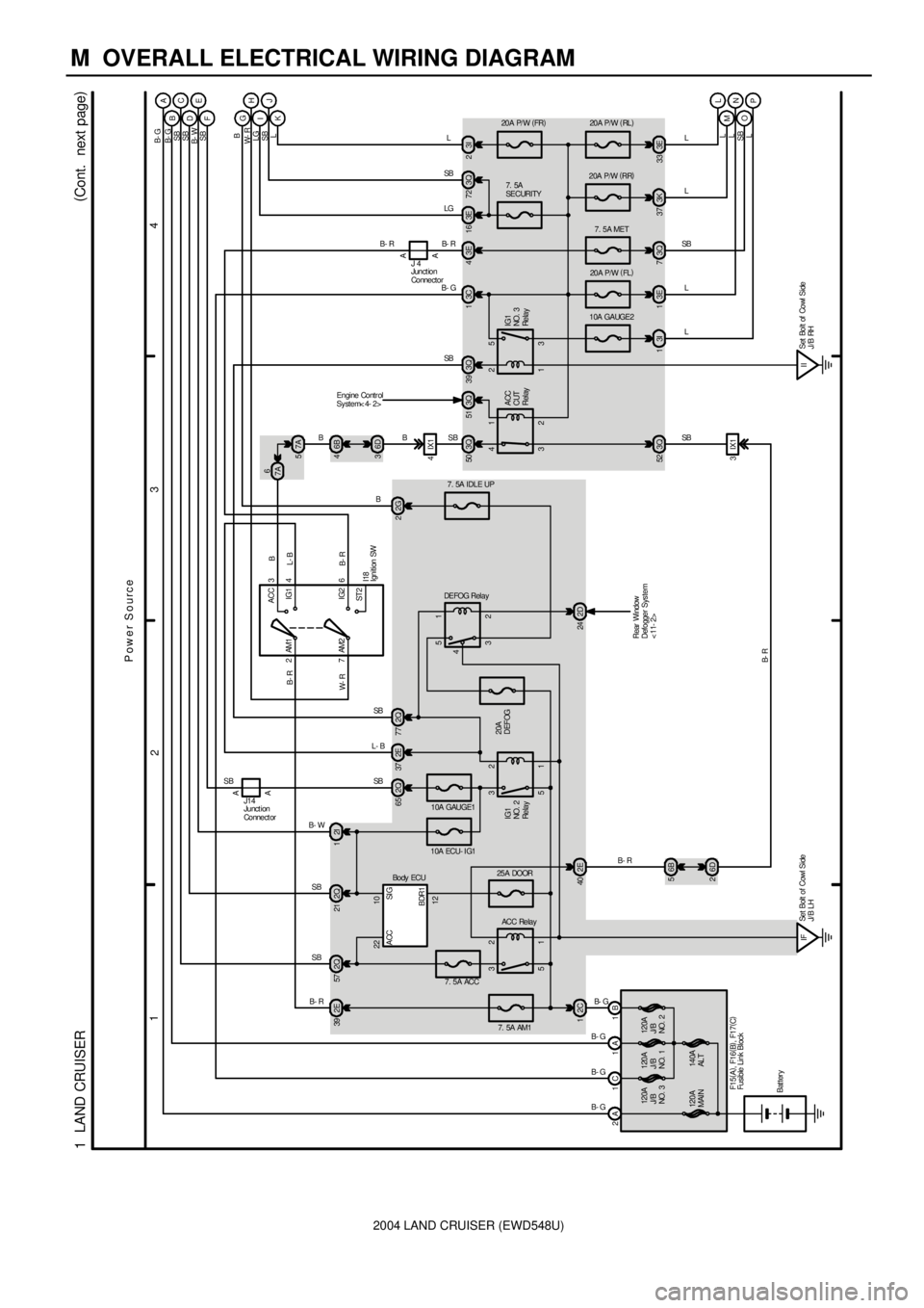
M OVERALL ELECTRICAL WIRING DIAGRAM
1
234
1 LAND CRUISER(
Cont. next page)
2A 1C 1A 1B
7. 5A AM1
2C 12E 39
1 2
5 3
1 2
5 3
2E 40
IFSet Bolt of Cowl Side
J/ B LH
7. 5A ACC2Q 57
10A GAUGE1
2Q 65 2E37 2Q772
7ACC
IG1
IG2
ST 2 AM13
4
6 AM2
6B 5
6D 26B 4
6D 3
4IX1
A A
3E 4 3Q 50 3Q51
3 4
2 1
1 2
3 5 3Q 39 3C1
7. 5A
SECURITY 20A P/ W (
FR)
3E 16 2
IISet Bolt of Cowl Side
J/B RH 3Q 52
3IX1
Bat tery
B- GB- GB- R L- BSBB- R
I18
B- R
SB B
IG1
NO. 3
Re la y ACC
CUT
Relay
SB
B- R
SB B- G
B- R
ACC Relay
120A
MAI N120A
J/B
NO. 3120A
J/B
NO. 1
140A
AL T120A
J/B
NO. 2
F1 5(
A)
, F16(
B)
, F17(
C)
B- G
B- G 10A ECU- I G1
2I 1 2Q 21
3 5
2 1
4
20A
DEFOG
IG1
NO. 2
Re la y
2D 24
7. 5A IDLE UP
2G 2
DE FOG Rel a y
3Q 7 3I 13E13K37 3E33
7. 5A MET
10A GAUGE220A P/W (
FL) 20A P/W (
RR) 20A P/W (
RL)
L
M
N
O
P A
B
DC
E
F
G
IH
K A A
LGL
L
L
L SB
SBB
SB
B- W
SB
SB
B- R
W- RL- BB
Rear Window
Defogger Sys tem
<11- 2>
J14J 4
Engine Contr ol
System< 4- 2>
L
L
SB
L L LG W- RB SB B- WSB SB B- G B- G
Power Source
3Q 72 3I
L
J
SB
SB
B- R
Ignition SW
Junction
Connector
Fusible Link Block
Junct ion
Connect or
25A DOOR
22 10
12SI G ACC
BDR1
Bo dy ECU B
6
7A
7A 5
Page 1978 of 3115
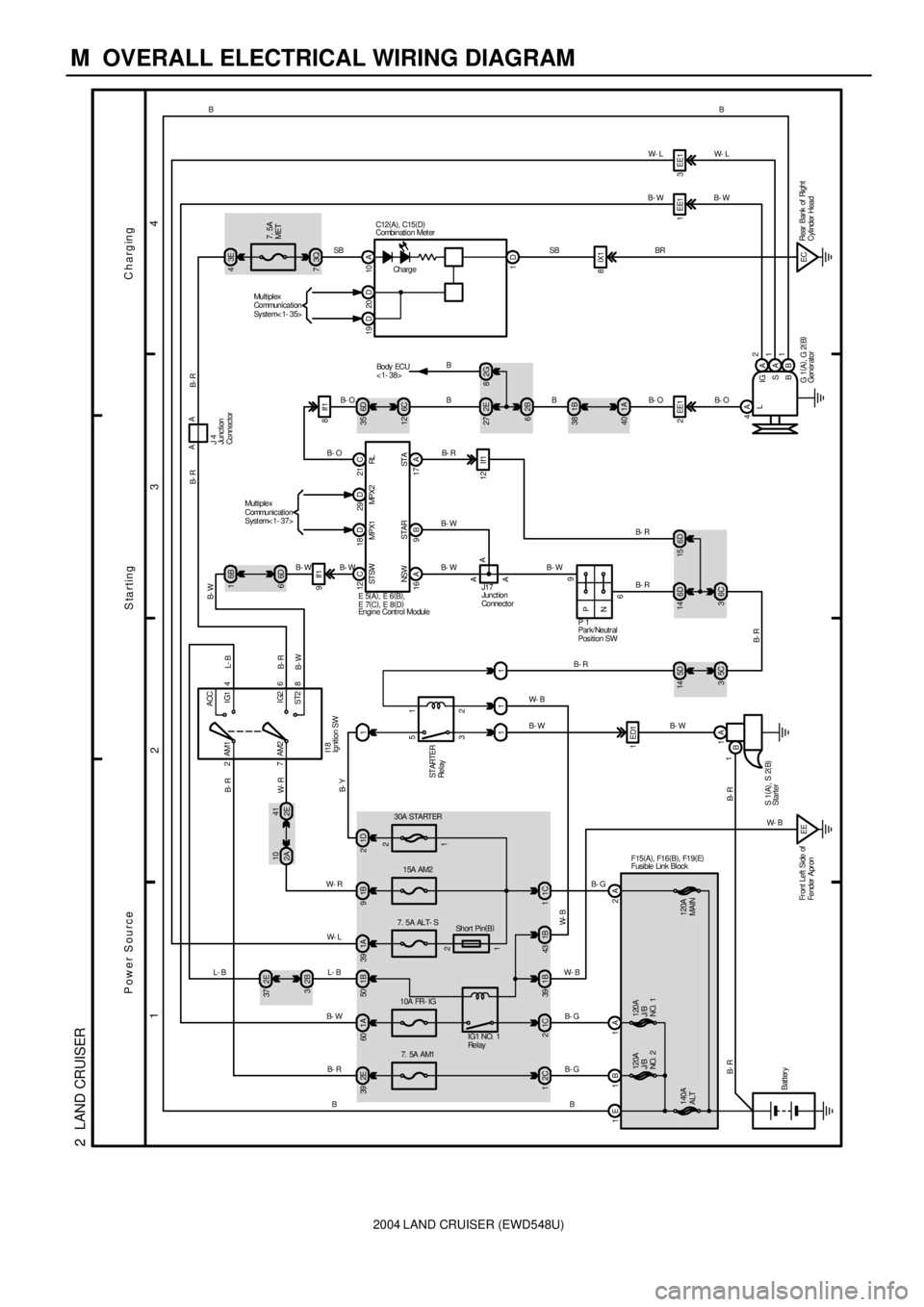
2004 LAND CRUISER (EWD548U)
M OVERALL ELECTRICAL WIRING DIAGRAM
1
234
2 LAND CRUISER
140A
ALT2C
1
7. 5A AM1
2E 39B- G
B
1A 60
15A AM2 30A STARTER
1B 9
1C
Bat teryAM2 7
8 6 4 AM1
ST2IG2 IG1 ACC
2
2 1
3 5
11
1A
B1ED1
16
SB
9
P
N3E 4
7. 5A
MET
3Q 7
2E 27
62B
1B 38
40 1A
2EE1
4A
L
A2
A
B IG
S
B1EE1 3EE1
Charging
Starting Power Source
B- R
W- RL- B
B- R
B- W
B- R B- R
B- W
B- R
B W- RB- GB- W B- R B- W B
BB-OB- WW- L
B- O B- WW- LB
ST ARTER
Re l ay
1 1 11 2
120A
J/B
NO. 2120A
J/B
NO. 1 1E 1B 2A1A1C 2
B- G
1A 39
7. 5A ALT- S
IG1 NO. 1
Re l ay
1B 50
10A FR- IG
41
2E 10
2A
Sh or t Pi n(
B)
I18
S 1(
A)
, S 2(
B) 1B 39 1B43
EE
F15(
A)
, F16(
B)
, F19(
E)
1
Fr ont Left Side of
Fender Apr on1D 21B- Y 2B 32E 37
L- B W- L
L- B
6D 66B 1
6D 14
6C 36D 15
P 1
A A 12 C
16 A 9 B 17 A21 C
E 5(
A)
, E 6(
B)
,
E 7(
C)
, E 8(
D)
6D 35
6C 12
B- O
B- W B- WB- RB C12(
A)
, C15(
D)
J17
A
B- R
B- W W- BB- R
W- B
W- B
G 1(
A)
, G 2(
B) ST SW
NS W S TA R ST ARL10 A
1D
W- B
5D 14
5C 3
B- RAA
J 4 B- R B- R
120A
MAIN 1 2
SBEC 8IX1BR
Ch ar g eRear Bank of Right
Cylinder Head 2G 8
B
Bo dy ECU
< 1- 38> Combination Meter
Engine Cont rol ModuleGener ator Ignition SW
Park/ Neutral
Position SW
Starter
Junction
Connector
Junc tion
Connec tor
Fusible Link Block
29 D 18 DMultiplex
Communication
Syst em< 1- 37>
20 D 19 DMultiplex
Communication
Sy st e m< 1- 3 5>
MPX2 MPX1
B- W B- W
B- W
B- O
9If1
8If1
12 If1
Page 1979 of 3115
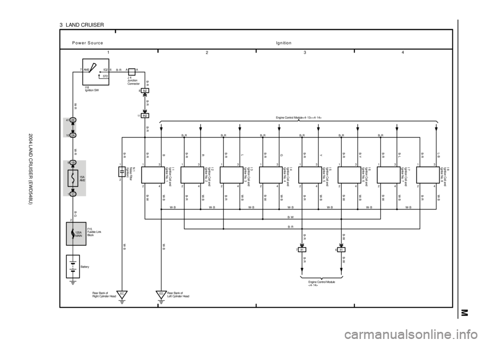
2004 LAND CRUISER (EWD548U)
M
1
234
3 LAND CRUISER
Bat tery 15A
AM2 1B 97IG2
ST2 AM2 6
24 13
B- RL- B W- B
24 13B- RB- L W- B
24 13B- R B- Y W- B
24 13B- RYW-B
24 13B- RGW-B
24 13B- RLW-B
24 13B- RRW-B
24 13B- RBW-BIN2 11
2 1
EC
Ign ition Power Source
B- R
B- R B- R B- R B- R B- R B- R
W- B W- B W- B W- B W- B W- B W- B
B- W
B- R
B- R
B- W
B- W
B- R
B- W
B- R
B- R
B- WW- B
W- B B- R B- R
W- R W- R B- GB- R B- W
Engine Control Module
< 4- 14> Engine Control Module< 4- 13> < 4- 14>
1C 12E 41
2A 10
F1 58Ib2
B- R
EDRear Bank of
Left Cylinder Head Rear Bank of
Right Cylinder Head7 If1 6 If1
B- R B- W
N 1 I 1 I 2 I 3 I 4 I 5 I 6 I 7 I 8
I18AA
J 4
B- R
120A
MAIN
I gnit ion Coil and
Igniter No. 1 I gnit ion Coil and
Igniter No. 2 I gnit ion Coil and
Igniter No. 3 I gnit ion Coil and
Igniter No. 4 I gnit ion Coil and
Igniter No. 5 I gnit ion Coil and
Igniter No. 6 I gnit ion Coil and
Igniter No. 7 I gnit ion Coil and
Igniter No. 8
Ignition SW
Noise Filter
(
Ignition)Junc tion
Connec tor
Fus ible Link
Bl oc k 2
Page 1983 of 3115
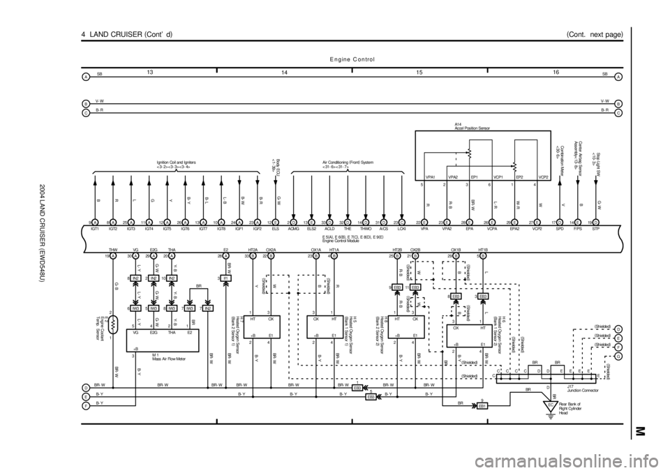
2004 LAND CRUISER (EWD548U)
M
13
141516
4 LAND CRUISER (
Cont' d)(
Cont. next page)
19A 30A 29A 20A
542
31A 28
G- B L- Y G- WY- B BR- W
BR- W BR- W
BR- WB- Y BR- WTHW VG E2G THA E2
VG E2G THA
+BE2
BR- W 1 2
Y- B
G- W
L- Y
8IN2 2IN2 10IN2
6IW3 5IW3 8IW3
Y- B
G- W
L- Y7IW3 7 IN23If1
M 19
H 8
EB3 1
B- Y 33 B 22 B
13
24 HT 2A OX2 A
HT OX
+B E1
Y W
B- Y
23 B 4 B
31
24 OX1A HT1A
OX HT
+B E1
B R
B- Y BR- W H 5
25 B 21 B
13
24 HT 2B OX2 B
HT OX
+B E1
R- BW
B- Y BR- W
29 B 5 B
31
24 OX1B HT1B
OX HT
+B E1
BLBR-WH 6
EC EB3
BR- W
B- Y BR- W BR- W 9A
IGT1
B
8A
IGT2
R25 A
IGT3
L11 A
IGT4
G12 A
IGT5
Y26 A
IGT6
B- Y13 A
IGT7
B- LBR- W
12 E
ELS2D
ACMG13 E
EL S233 D
ACLD32 D
THE L CKIC 23 31 D
A/CS THWOD 14 Air Conditioning (
Front)
System
< 31- 6> < 31- 7> Ignition Coil and Igniters
<3- 2><3- 3><3- 4>
VPAE 22
VPA2E 23
EPAE 28
H 7
VCPAE 26
3EB3EPA2E 29
EB3 8VCP2E 27 523614
R R- B BR- WL- R W- RW
A1 4
EB3
5
(
Shielded)
(
Shielded) (
Shielded)BR
Rear Bank of
Right Cylinder
He ad 10 A
IGT8
L- B24 A
IGF1
B- W23 A
IGF2
B- R
EB3 1117 D
V14 E
B
Cent er Air bag Sens or
Assembly< 13- 8>19 D
G- W
Stop Light SW
<10- 3>
SPD F/PSCombination Meter
<30- 6>
STP
B- Y
BRBR
BR- W
B- Y B- YBR- W
R- BWBL
B
A
C
D
E
FB- RSB
V- W
BR- W
B- Y
B- Y
E ngine C ontrol
E 2
A
B
C
F
G SB
V- W
B- R
(
Shielded) E 5(
A)
, E 6(
B)
, E 7(
C)
, E 8(
D)
, E 9(
E)
D
E (
Shielded)
(
Shielded)
B- Y (
Shielded)
(
Shielded)
BR
(
Shielded)
D DD BR BR
EB19
BR
BR
C
CCCC E E E E
J17
(
Shielded)
E
(
Shielded) (
Shielded)
(
Shielded)
(
Shielded) VPA1 VPA2 EP1 VCP1 EP2 VCP2
G- W
Body ECU
<1- 39>
Ac cel Pos ition Sens or
Engine Coolant
Temp. Sensor
Engine Cont rol Module
Heated Oxygen Sensor
(
Bank 1 Sens or 1) Heated Oxygen Sensor
(
Bank 1 Sens or 2)
Heated Oxygen Sensor
(
Bank 2 Sens or 1) Heated Oxygen Sensor
(
Bank 2 Sens or 2)
Mass Air Flow Met er
J unction Connec tor
Page 1986 of 3115
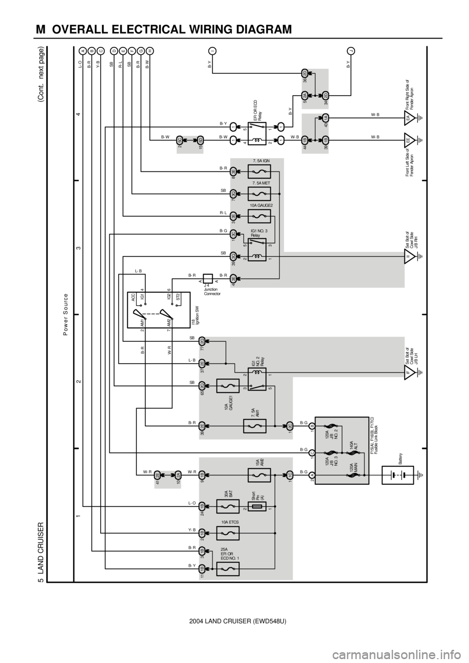
2004 LAND CRUISER (EWD548U)
M OVERALL ELECTRICAL WIRING DIAGRAM
1
234
5 LAND CRUISER(
Cont. next page)
30A
BAT 1B 24 1B9
15A
AM2
1C 12E 41
2A 10
2A 1C 1B7. 5A
AM1
2C 12E 39
1 2
5 3
IFSet Bolt of
Cowl Side
J/B LH 10A
GAUGE12Q 65 2E37 2Q772
7ACC
IG1
IG2
ST2 AM1 4
6 AM2
A A
3E 4
1 2
3 5 3Q 39 3C1
10A GAUGE27. 5A MET
3E 33Q7
IISet Bolt of
Cowl Side
J/B RH Sh or t
Pi n
(
A)
Battery
B- G B- G B- G
L- O W- R W- RL- BSB B- R
I18
B- RIG1 NO. 3
Re la y
SB B- G
B- R
W- R
IG1
NO. 2
Re la y
10A ETCS
25A
EFI OR
ECD NO. 1
1B 2 1B 11 1B3
2 4
1 5 11
11
1B 39 1A43 1B 44
EE Front Left Side of
Fender ApronEAFr ont Right Side of
Fender Apr on2A 5
2D 34I
J A
B
C
D
E
F
G
5C 2
5D 15
7. 5A IGN
3E 8H
R- LSB B- R B- WB- Y
B- W W- B W- BW- B
B- Y B- R Y- B
L- O
B- R
Y- B
SB
R- L
SB
B- R
B- W
120A
MAIN140A
AL T 120A
J/ B
NO. 3120A
J/B
NO. 2
B- R
EFI OR ECD
Relay
SB L- B
B- Y
B- Y
Power Source
J 4
F1 5(
A)
, F16(
B)
, F17(
C)B- Y 2
1Ignition SW
Junc tion
Connec tor
Fusible Link Block2D 36