Page 625 of 3115

Component to be alignedSection of repair manual for
relevant model
Front WheelsSuspension and Axle (SA) section
Rear WheelsSuspension and Axle (SA) section
Plopeller ShaftPropeller Shaft (PR) section
AIRBAG SENSOR ASSEMBLY
�Never reuse the airbag sensor assembly involved in a collision when the SRS has deployed.
�The connectors to the airbag sensor assembly should be connected or disconnected with the sensor
mounted on the floor. If the connectors are connected or disconnected while the airbag sensor as-
sembly is not mounted to the floor, it could cause undesired ignition of the supplemental restraint sys-
tem.
�Work must be started after 90 seconds from the time the ignition switch is turned to the ºLOCKº posi-
tion and the negative (-) terminal cable is disconnected from the battery, even if only loosening the
set bolts of the airbag sensor assembly.
WIRE HARNESS AND CONNECTOR
�The SRS wire harness is integrated with the cowl wire harness assembly and floor wire harness as-
sembly. The wires for the SRS wire harness are encased in a yellow corrugated tube. All the connec-
tors for the system are also a standard yellow color. If the SRS wire harness becomes disconnected
or the connector becomes broken due to an accident, etc., repair or replace it as shown on page.
2. BRAKE SYSTEM
The brake system is one of the most important safety components. Always follow the directions and
notes given in section BR of the repair manual for the relevant model year when handling brake sys-
tem parts.
NOTICE: When repairing the brake master cylinder or TRAC system, bleed the air out of the TRAC
system.
3. DRIVE TRAIN AND CHASSIS
The drive train and chassis are components that can have great effects on the running performance
and vibration resistance of the vehicle. After installing components in the sections listed in the table
below, perform alignments to ensure correct mounting angles and dimensions. Particularly accurate
repair of the body must also be done to ensure correct alignment.
HINT: Correct procedures and special tools are required for alignment. Always follow the directions
given in the repair manual for the relevant model during alignment and section Dl of this manual.
4. COMPONENTS ADJACENT TO THE BODY PANELS
Various types of component parts are mounted directly on or adjacently to the body panels. Strictly ob-
serve the following precautions to prevent damaging these components and the body panels during
handling.
�Before repairing the body panels, remove their components or apply protective covers over the com-
ponents.
�Before prying components off using a screwdriver or a scraper, etc., attach protective tape to the tool
tip or blade to prevent damaging the components and the body paint.
�Before removing components from the outer surface of the body, attach protective tape to the body
to ensure no damage to painted areas.
HINT: Apply touch-up paint to any damaged paint surfaces.
�Before drilling or cutting sections, make sure that there are no wires, etc. on the reverse side.
INTRODUCTIONIN-8
Page 710 of 3115
HINT: For symbols, capital letters indicate right side of vehicle,
small letters indicate left side of vehicle (Seen from rear).
(Three-Dimensional Distance)
mm (in.)
Hole dia.
12 (0.47)
9 (0.35)
11y9 (0.43
y0.35)
6 (0.24) nut Name
Radiator installation hole
Radiator installation hole
Radiator installation hole
Hood lock support installation nut Symbol
F, f
G
g
H Hole dia.
6 (0.24) nut
6 (0.24) nut
6 (0.24) nut
10 (0.39) Name
Front fender installation nut
Front fender installation nut
Front fender installation nut
Cowl top panel vehicle center mark
Front fender apron standard hole Symbol
A, a
B, b
C, c
D
E, e
BODY DIMENSION DRAWINGS
ENGINE COMPARTMENT
BODY DIMENSIONSDI-3
Page 711 of 3115
1,472
(57.95)N-n O-o
1,613
(63.50)Vehicle Dimensions Left e Right
P-p
1,619
(63.74)Q-q
1,330
(52.36)R-r
1,442
(56.77)S-s
1,607
(63.27)N-r
or
n-R
1,649
(64.92)N-s
or
n-S
1,782
(70.16)1,734
(68.27)O-s
or
o-S
1,875
(73.82)P-q
or
p-QR-s
or
r-S
1,692
(66.61)
HINT: For symbols, capital letters indicate right side of vehicle,
small letters indicate left side of vehicle (Seen from rear).
(Three-Dimensional Distance)
mm (in.)
Hole dia.
Name
Roof side rail assembly mark
Quarter panel assembly mark
Quarter panel assembly mark Symbol
Q, q
R, r
S, s Hole dia.
Name
Center body pillar assembly mark
Center body pillar assembly mark
Rocker panel assembly mark Symbol
N, n
O, o
P, p
BODY OPENING AREAS
(Side View-Rear)
BODY DIMENSIONSDI-5
Page 712 of 3115
HINT: For symbols, capital letters indicate right side of vehicle,
small letters indicate left side of vehicle (Seen from rear).
mm (in.)
(Three-Dimensional Distance)
Hole dia.
8 (0.31) nut
8 (0.31) nut Name
Tail gate lock striker installation nut
Tail gate hinge installation nut-outer Symbol
C, c
D, d Hole dia.
8.2 (0.323)
11y8.2 (0.43
y0.323)
8 (0.31) nut Name
Back door hinge installation hole-outer = front tip: RH
Back door hinge installation hole-outer = front tip: LH
Back door damper stay installation nut Symbol
A
a
B, b
BODY OPENING AREAS
(Rear View: Lift-Up Type)
BODY DIMENSIONSDI-6
Page 713 of 3115
HINT: For symbols, capital letters indicate right side of vehicle,
small letters indicate left side of vehicle (Seen from rear).
mm (in.)
(Three-Dimensional Distance)
Hole dia.
8 (0.31) nut
12.5y8.5 (0.492y0.335)
Name
Back door hinge installation nut-lower
Rear floor finish plate installation hole Symbol
C, c
D, d Hole dia.
10 (0.39)
8 (0.31) nut Name
Back door opening frame standard hole
Back door hinge installation nut-upper Symbol
A, a
B, b
BODY OPENING AREAS
(Rear View: Swing Type)
BODY DIMENSIONSDI-7
Page 714 of 3115

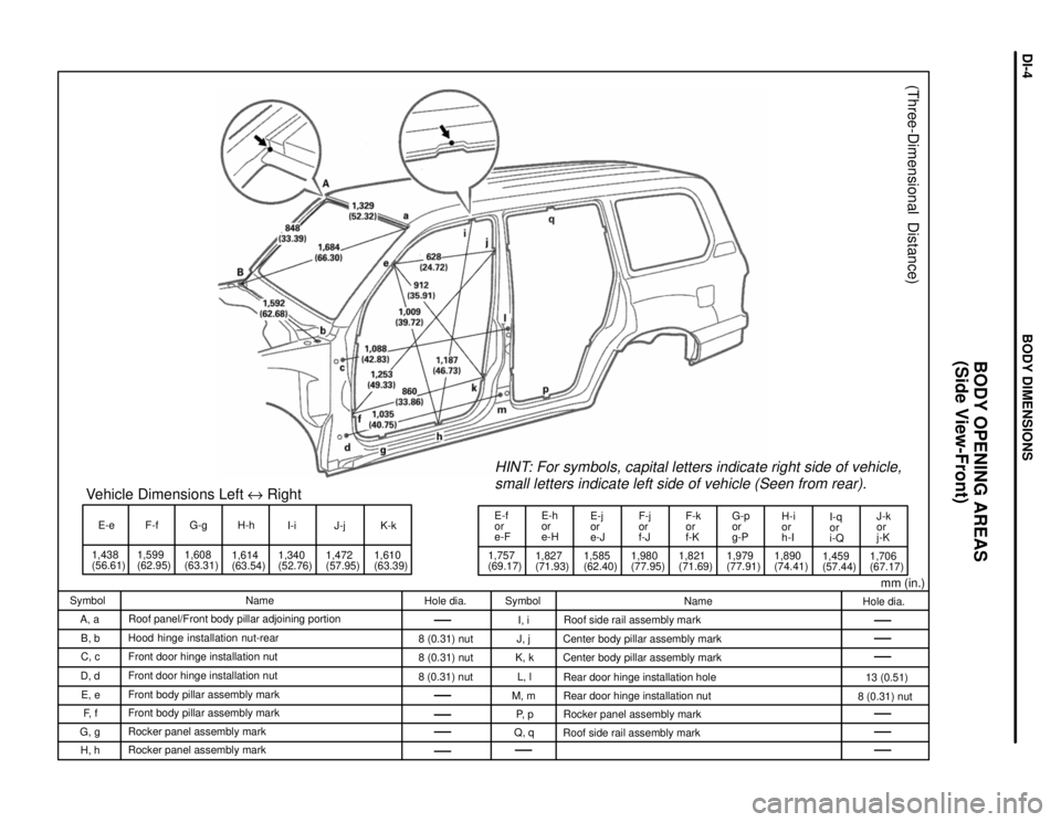
E-e
1,438
(56.61)1,599
(62.95)F-f
1,608
(63.31)G-gVehicle Dimensions Left e Right
1,614
(63.54)H-h
I-i
1,340
(52.76)1,472
(57.95)J-j K-k
1,610
(63.39)1,757
(69.17)E-f
or
e-F
1,827
(71.93)E-h
or
e-HE-j
or
e-J
1,585
(62.40)1,980
(77.95)F-j
or
f-J
1,821
(71.69)F-k
or
f-KG-p
or
g-P
1,979
(77.91)H-i
or
h-I
1,890
(74.41)I-q
or
i-Q
1,459
(57.44)1,706
(67.17)J-k
or
j-K
HINT: For symbols, capital letters indicate right side of vehicle,
small letters indicate left side of vehicle (Seen from rear).
(Three-Dimensional Distance)
mm (in.)
Hole dia.
13 (0.51)
8 (0.31) nut Name
Roof side rail assembly mark
Center body pillar assembly mark
Center body pillar assembly mark
Rear door hinge installation hole
Rear door hinge installation nut
Rocker panel assembly mark
Roof side rail assembly mark Symbol
I, i
J, j
K, k
L, l
M, m
P, p
Q, q Hole dia.
8 (0.31) nut
8 (0.31) nut
8 (0.31) nut Name
Roof panel/Front body pillar adjoining portion
Hood hinge installation nut-rear
Front door hinge installation nut
Front door hinge installation nut
Front body pillar assembly mark
Front body pillar assembly mark
Rocker panel assembly mark
Rocker panel assembly mark Symbol
A, a
B, b
C, c
D, d
E, e
F, f
G, g
H, h
BODY OPENING AREAS
(Side View-Front)
BODY DIMENSIONSDI-4
Page 715 of 3115
(Three-Dimensional Distance)
mm (in.)
Hole dia.
18.5 (0.728)
30 (1.18)
18.5 (0.728)
18.5 (0.728)
16 (0.63)
70 (2.76) Name
Lower control arm installation hole-inner
Body mounting hole
Upper control arm installation hole-inner
Lateral control rod installation hole-front
Body mounting hole
Body mounting hole Symbol
G, g
H, h
I, i
J
K, k
L, l Hole dia.
24 (0.94)
16.5 (0.650)
24 (0.94)
60 (2.36)
18.5 (0.728)
30 (1.18) Name
Body mounting bole
Lateral control rod installation hole-rear
Shock absorber installation hole
Body mounting hole
Leading arm installation hole-inner
Body mounting hole Symbol
A, a
B
C, c
D, d
E, e
F, f
FRAME DIMENSION
FZJ105 series (RHD)
w HZJ105 series (RHD)
BODY DIMENSIONSDI-10
Page 716 of 3115
Wheel Base 2,850 (112.20)
Imaginary
Standard
Line
mm (in.)
(Two-Dimensional Distance)
Hole dia.
18.5 (0.728)
30 (1.18)
18.5 (0.728)
18.5 (0.728)
16 (0.63)
70 (2.76) Name
Lower control arm installation hole-inner
Body mounting hole
Upper control arm installation hole-inner
Lateral control rod installation hole-front
Body mounting hole
Body mounting hole Symbol
G, g
H, h
I, i
J
K, k
L, l Hole dia.
25 (0.94)
16.5 (0.650)
24 (0.94)
60 (2.36)
18.5 (0.728)
30 (1.18) Name
Body mounting hole
Lateral control rod installation hole-rear
Shock absorber installation hole
Body mounting hole
Leading arm installation hole-inner
Body mounting hole Symbol
A, a
B
C, c
D, d
E, e
F, f
FRAME DIMENSION
FZJ105 series (RHD)
w HZJ105 series (RHD) (Cont'd)
BODY DIMENSIONSDI-11