Page 578 of 2389
HINT: During reassembly please refer to the spring specifications above to help discriminate the
different springs.
SECTIONAL VIEW OF VALVE BODY SPECIFICATIONS OF VALVE BODY SPRINGS
No. 2 accumulator control valveCoil outer diameter
mm (in.) Free length mm (in.)
Secondary regulator valve
Low coast modulator valve
Primary regulator valve Pressure relief valve
Second lock valveTotal No. of coils
1±2 shift valve 3±4 shift valve
2±3 shift valveLight Green
Light Green Check valve
Orange Spring
Purple PurpleColor
None None
None None Gray
± AUTOMATIC TRANSAXLEComponent Parts (Valve Body A540E and A540H)AT±316
Page 690 of 2389
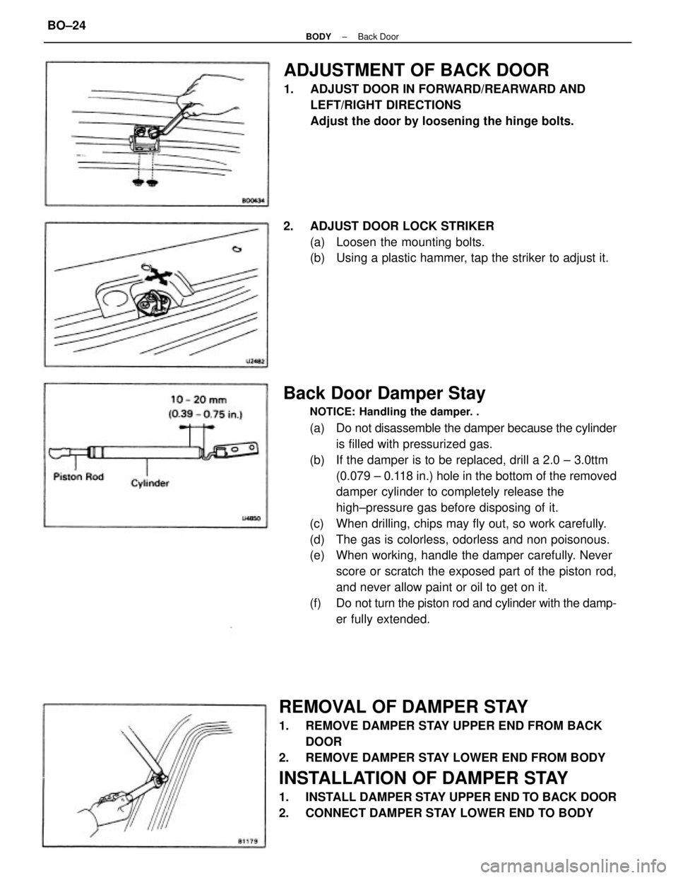
Back Door Damper Stay
NOTICE: Handling the damper. .
(a) Do not disassemble the damper because the cylinder
is filled with pressurized gas.
(b) If the damper is to be replaced, drill a 2.0 ± 3.0ttm
(0.079 ± 0.118 in.) hole in the bottom of the removed
damper cylinder to completely release the
high±pressure gas before disposing of it.
(c) When drilling, chips may fly out, so work carefully.
(d) The gas is colorless, odorless and non poisonous.
(e) When working, handle the damper carefully. Never
score or scratch the exposed part of the piston rod,
and never allow paint or oil to get on it.
(f) Do not turn the piston rod and cylinder with the damp-
er fully extended.
REMOVAL OF DAMPER STAY
1. REMOVE DAMPER STAY UPPER END FROM BACK
DOOR
2. REMOVE DAMPER STAY LOWER END FROM BODY
INSTALLATION OF DAMPER STAY
1. INSTALL DAMPER STAY UPPER END TO BACK DOOR
2. CONNECT DAMPER STAY LOWER END TO BODY
ADJUSTMENT OF BACK DOOR
1. ADJUST DOOR IN FORWARD/REARWARD AND
LEFT/RIGHT DIRECTIONS
Adjust the door by loosening the hinge bolts.
2. ADJUST DOOR LOCK STRIKER
(a) Loosen the mounting bolts.
(b) Using a plastic hammer, tap the striker to adjust it.
± BODYBack DoorBO±24
Page 777 of 2389

Replace fuse and check for short
Replace bulb
Check switch
Check switch
Check switch
Check relay
Repair a s necessary ºDOMEº fuse blown
Bulb burned out
Door courtesy switch faulty
Unlock warning switch faulty
Buckle switch faulty
Seat belt warning relay faulty
Wiring or ground faultyºGAUGEº fuse blown
Bulb burned out
Brake fluid level warning switch faulty
Parking brake switch faulty
Wiring or ground faultyReplace fuse and check for short
Replace bulb
Check switch
Check switch
Repair as necessary ºGAUGEº fuse blown
Water temperature gauge faulty
Water temperature sender gauge faulty
Wiring or ground faulty
ºGAUGEº fuse blown
Buibburned out
oil pressure warning switch faulty
Wiring or ground faultyºGAUGEº fuse blown
Bulb burned out
Fuel level warning switch faulty
Wiring or ground faulty
Replace fuse and check for short
Replace bulb
Check switch
±Repair as necessaryReplace fuse and check for short
Replace bulb
Check switch
Repair as necessary
Replace fuse and check for short
Replace bulb
Check switch
Repair as necessaryReplace fuse and check for short
Check gauge
Check sender gauge
Repair as necessaryReplace fuse .and check for short
Check gauge
Check sender gauge
Repair as necessary
COMBINATION METER
Troubleshooting
ºGAUGEº fuse blown
Bulb burned out
Door courtesy switch faulty
Wiring or ground faultyReplace fuse and check for short
Check tachometer
Repair as necessary
ºGAUGEº fuse blown
Fuel gauge faulty
Sender gauge faulty
Wiring or ground faultyºGAUGEº fuse blown
Tachometer faulty
Wiring faulty
Low oil pressure warning
light does not lightWater temperature
gauge does not
operate
Seat belt warning
does not operate
(Canada)Tachometer does not
operate
Brake warning light does
not lightFuel gauge does not
operate
Open door warning light
does not lightFuel level warning light
does not light
BE±40
BE±13
BE±41
BE±41BE±3
BE±38
BE±39BE±3
BE±36
BE±37 Possible cause
BE±3
BE±36
BE±40
BE±40 Problem
Remedy
BE±40BE±39BE±37Page
BE±3BE±3
BE±3
BE±3
BE±3
± BODY ELECTRICAL SYSTEMCombination MeterBE±31
Page 778 of 2389
Light Control Rheostat
TAIL Fuse
IGN Fuse
Water Temperature Sender Gauge
Ground
Seat Beh Warning Relay
Brake Fluid Level Warning Switch and Parking
Brake Switch
CHARGE Fuse
TCCS ECU
A.B.S. ECU
Cruise Control ECU and ECT ECU
Ground
Fuel Sender Gauge Terminal 3
Fuel Sender Gauge Terminal 2
GAUGE Fuse
DOME Fuse
Door Courtesy Switch
Low Oil Pressure Switch
Light Failure Sensor
Combination Meter and Gauges
(w/o Tachometer)
Turn Signal Switch Terminal 28
Ground
Turn Signal Switch Terminal 25
Turn Signal Switch Terminal 23 (USA)
HEAD±HI (RH) Fuse (CANADA)
A/T Oil Temperature Switch
COMBINATION METER CIRCUIT
Wiring Connector Side
No.
± BODY ELECTRICAL SYSTEMCombination MeterBE±32
Page 779 of 2389
Light Control Rheostat
TAIL Fuse
IGN Fuse
Water Temperature Sender Gauge
Ground
Seat Belt Warning Relay
Brake Fluid Level Warning Switch and Parking
Brake Switch
CHARGE Fuse
TCCS ECU ,
A. B. S. ECU
Cruise Control ECU and ECT ECU
Ground
Fuel Sender Gauge Terminal 3
Fuel Sender Gauge Terminal 2
. GAUGE Fuse
DOME Fuse
Door Courtesy Switch
Low Oil Pressure Switch
Light Failure Sensor
Turn Signal Switch Terminal 28
Ground
Turn Signal Switch Terminal 25
Turn Signal Switch Terminal 23 (USA)
HEAD±HI (RH) Fuse (CANADA)
A/T Oil Temperature Switch
Igniter
Combination Meter and Gauges
(w/ Tachometer)
COMBINATION METER CIRCUIT
Wiring Connector Side
No.
± BODY ELECTRICAL SYSTEMCombination MeterBE±33
Page 785 of 2389
Low Oil Pressure Warning
INSPECTION OF PRESSURE WARNING
1. INSPECT WARNING LIGHT OPERATION
(a) Disconnect the connector from the pressure switch
and ground the connector on the wire harness side.
(b) Turn the ignition switch ON, check that t he warning
light lights.
If the warning light does not light, test the bulb.
2. INSPECT PRESSURE SWITCH OPERATION
(a) Disconnect the connector from the switch.
(b) Check that there is continuity between terminal and
ground with the engine stopped.
(c) Check that there is no continuity between terminal
and ground with the engine running.
HINT: Oil pressure should be over 0.3 kg/cm2 (4.3 psi, 29
kPa).
If operation is not as specified, replace the switch.If resistance value is not as specified, replace the send-
er gauge. 3. MEASURE SENDER GAUGE RESISTANCE
Measure the resistance between terminal and ground.
ater temperature oC
(OF)Resistance (�)
N i ppo nde nso Yazaki
± BODY ELECTRICAL SYSTEMCombination MeterBE±39
Page 852 of 2389
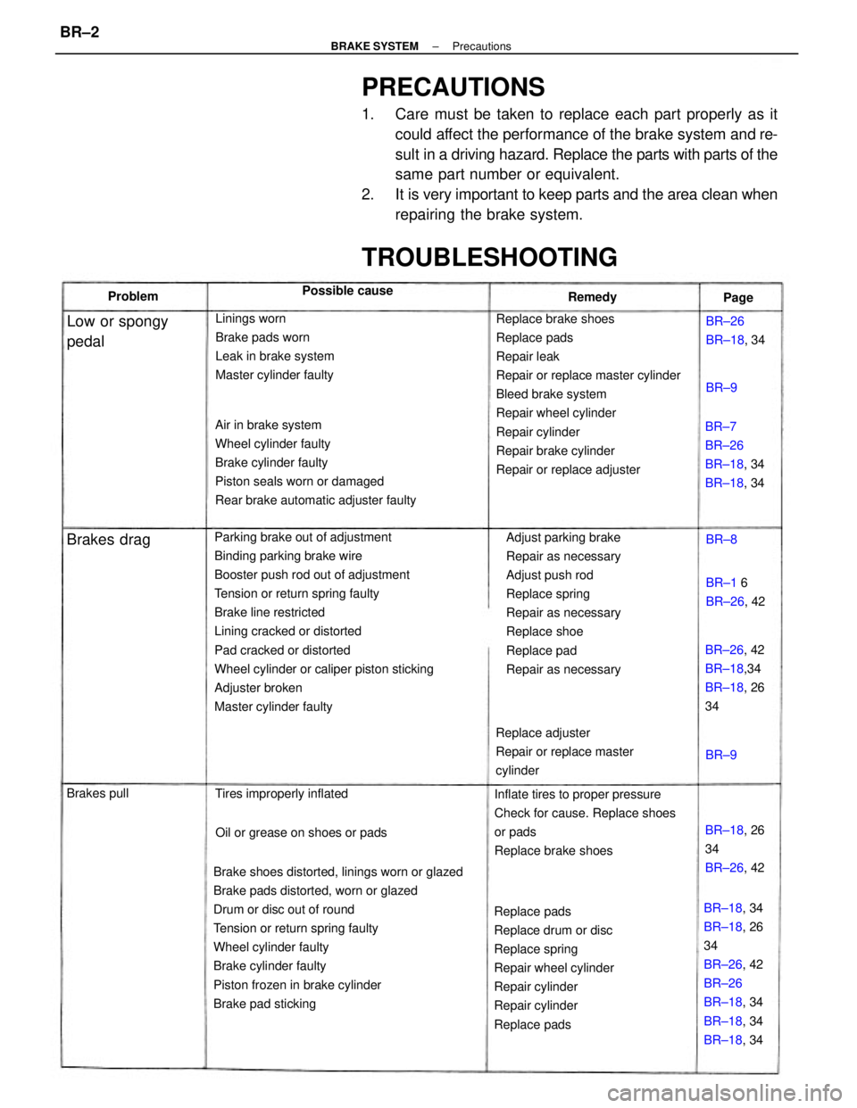
PRECAUTIONS
1. Care must be taken to replace each part properly as it
could affect the performance of the brake system and re-
sult in a driving hazard. Replace the parts with parts of the
same part number or equivalent.
2. It is very important to keep parts and the area clean when
repairing the brake system.
Parking brake out of adjustment
Binding parking brake wire
Booster push rod out of adjustment
Tension or return spring faulty
Brake line restricted
Lining cracked or distorted
Pad cracked or distorted
Wheel cylinder or caliper piston sticking
Adjuster broken
Master cylinder faulty
Brake shoes distorted, linings worn or glazed
Brake pads distorted, worn or glazed
Drum or disc out of round
Tension or return spring faulty
Wheel cylinder faulty
Brake cylinder faulty
Piston frozen in brake cylinder
Brake pad stickingReplace brake shoes
Replace pads
Repair leak
Repair or replace master cylinder
Bleed brake system
Repair wheel cylinder
Repair cylinder
Repair brake cylinder
Repair or replace adjuster Air in brake system
Wheel cylinder faulty
Brake cylinder faulty
Piston seals worn or damaged
Rear brake automatic adjuster faulty
Adjust parking brake
Repair as necessary
Adjust push rod
Replace spring
Repair as necessary
Replace shoe
Replace pad
Repair as necessary
Replace pads
Replace drum or disc
Replace spring
Repair wheel cylinder
Repair cylinder
Repair cylinder
Replace padsInflate tires to proper pressure
Check for cause. Replace shoes
or pads
Replace brake shoes Linings worn
Brake pads worn
Leak in brake system
Master cylinder faulty
BR±18, 34
BR±18, 26
34
BR±26, 42
BR±26
BR±18, 34
BR±18, 34
BR±18, 34 Replace adjuster
Repair or replace master
cylinder
TROUBLESHOOTING
BR±7
BR±26
BR±18, 34
BR±18, 34
BR±26, 42
BR±18,34
BR±18, 26
34
Oil or grease on shoes or pads Tires improperly inflated
BR±18, 26
34
BR±26, 42
Low or spongy
pedalBR±26
BR±18, 34
BR±1 6
BR±26, 42 Possible cause
Brakes drag
Brakes pullRemedy Problem
Page
BR±8
BR±9BR±9
± BRAKE SYSTEMPrecautionsBR±2
Page 853 of 2389
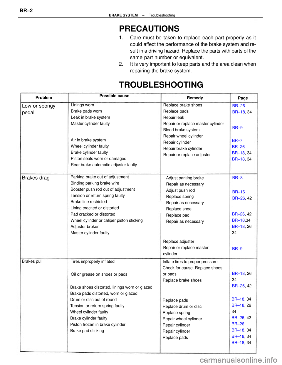
PRECAUTIONS
1. Care must be taken to replace each part properly as it
could affect the performance of the brake system and re-
sult in a driving hazard. Replace the parts with parts of the
same part number or equivalent.
2. It is very important to keep parts and the area clean when
repairing the brake system.
Parking brake out of adjustment
Binding parking brake wire
Booster push rod out of adjustment
Tension or return spring faulty
Brake line restricted
Lining cracked or distorted
Pad cracked or distorted
Wheel cylinder or caliper piston sticking
Adjuster broken
Master cylinder faulty
Brake shoes distorted, linings worn or glazed
Brake pads distorted, worn or glazed
Drum or disc out of round
Tension or return spring faulty
Wheel cylinder faulty
Brake cylinder faulty
Piston frozen in brake cylinder
Brake pad stickingReplace brake shoes
Replace pads
Repair leak
Repair or replace master cylinder
Bleed brake system
Repair wheel cylinder
Repair cylinder
Repair brake cylinder
Repair or replace adjuster Air in brake system
Wheel cylinder faulty
Brake cylinder faulty
Piston seals worn or damaged
Rear brake automatic adjuster faulty
Adjust parking brake
Repair as necessary
Adjust push rod
Replace spring
Repair as necessary
Replace shoe
Replace pad
Repair as necessary
Replace pads
Replace drum or disc
Replace spring
Repair wheel cylinder
Repair cylinder
Repair cylinder
Replace padsInflate tires to proper pressure
Check for cause. Replace shoes
or pads
Replace brake shoes Linings worn
Brake pads worn
Leak in brake system
Master cylinder faulty
BR±18, 34
BR±18, 26
34
BR±26, 42
BR±26
BR±18, 34
BR±18, 34
BR±18, 34 Replace adjuster
Repair or replace master
cylinder
TROUBLESHOOTING
BR±7
BR±26
BR±18, 34
BR±18, 34
BR±26, 42
BR±18,34
BR±18, 26
34
Oil or grease on shoes or pads Tires improperly inflated
BR±18, 26
34
BR±26, 42
Low or spongy
pedalBR±26
BR±18, 34
BR±16
BR±26, 42 Possible cause
Brakes drag
Brakes pullRemedy Problem
Page
BR±8
BR±9BR±9
± BRAKE SYSTEMTroubleshootingBR±2


