Page 347 of 2389
2. INSPECT DISCS, PLATES AND FLANGE
Check if the sliding surfaces of the discs, plates are
flange are worn or burnt. If necessary, replace them.
HINT:
wIf the lining of the disc is exfoliated or discolored, o
even a part of the printed numbers are defaced, re-
place all discs.
wBefore assembling new discs, soak them in ATF for
at least two hours.
INSPECTION OF FORWARD CLUTCH
1. INSPECT CLUTCH PISTON
(a) Check that the check ball is free by shaking the piston.
(b) Check that the valve does not leak by applying low pressure
compressed air. 6. IF NECESSARY, REMOVE OIL SEAL RINGS
Remove the two oil seal rings from the shaft.(b) Remove the two O±rings from the piston.
± AUTOMATIC TRANSAXLEComponent Parts (Forward Clutch) (A140L and A140E)AT±92
Page 383 of 2389
HINT: During re±assembly please refer to the spring specifications above to help discriminate be-
tween the different springs.
SECTIONAL VIEW OF VALVE BODY
SPECIFICATIONS OF VALVE BODY SPRINGS
Secondary Regulator Valve Spring
Primary Regulator Valve Spring
Cooler By±pass Valve Spring Lock±up Signal Valve Spring
Pressure Relief Valve SpringCoil Outer
Diameter mm (in.)
2±3 Shift Valve Spring 3±4 Shift Valve Spring
1±2 Shift Valve SpringFree Length
mm (in.)Number of
Coils SpringColor
None
NoneNone None
None None
None None
± AUTOMATIC TRANSAXLEComponent Parts (Valve Body) (A140E)AT±128
Page 395 of 2389
HINT: During re±assembly please refer to the spring specifications above to help discriminate be-
tween the different springs.
SECTIONAL VIEW OF VALVE BODY
SPECIFICATIONS OF VALVE BODY SPRINGS
Secondary Regulator Valve Spring
Primary Regulator Valve Spring Detent Regulator Valve Spring 3±4 Coast Shift Valve Spring Lock±up Signal Valve Spring
Cooler By±pass Valve Spring O/D Sequence Valve Spring
Pressure Relief Valve SpringCoil Outer
Diameter mm (in.)
2±3 Shift Valve Spring 1±2 Shift Valve SpringFree Length
mm (in.)Number of
Coils SpringColor
± AUTOMATIC TRANSAXLEComponent Parts (Valve Body) (A140L)AT±140
Page 419 of 2389
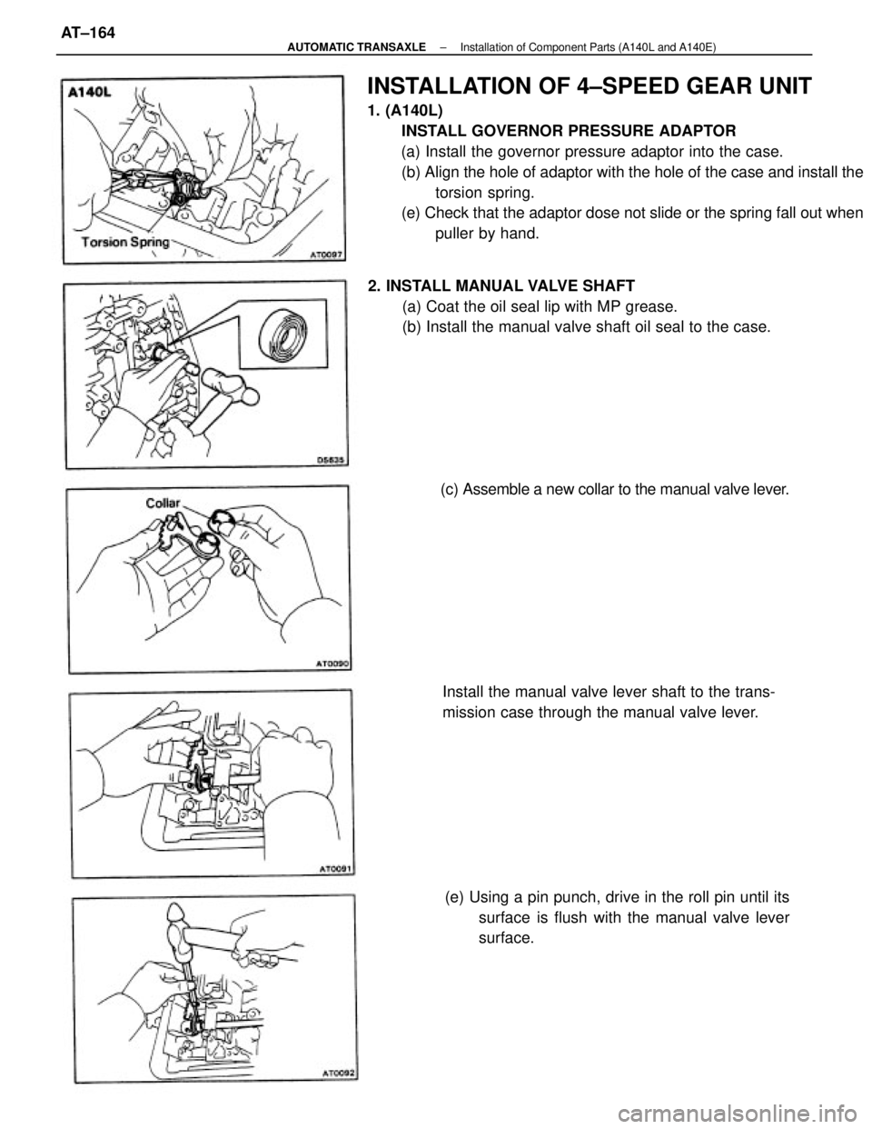
INSTALLATION OF 4±SPEED GEAR UNIT
1. (A140L)
INSTALL GOVERNOR PRESSURE ADAPTOR
(a) Install the governor pressure adaptor into the case.
(b) Align the hole of adaptor with the hole of the case and install the
torsion spring.
(e) Check that the adaptor dose not slide or the spring fall out when
puller by hand.
2. INSTALL MANUAL VALVE SHAFT
(a) Coat the oil seal lip with MP grease.
(b) Install the manual valve shaft oil seal to the case.
Install the manual valve lever shaft to the trans-
mission case through the manual valve lever.
(e) Using a pin punch, drive in the roll pin until its
surface is flush with the manual valve lever
surface. (c) Assemble a new collar to the manual valve lever.
± AUTOMATIC TRANSAXLEInstallation of Component Parts (A140L and A140E)AT±164
Page 460 of 2389

HYDRAULIC TEST
PREPARATION
(a) Warm up the transaxle fluid.
(b) Remove the transaxle case test plug and connect the hydraulic pressure gauge.
SST 09992±00094 (Oil pressure gauge)
NOTICE:
wPerform the test at normal operating fluid temperature (122 ± 176°F or 50 ± 80°C)
wThe line pressure test should always be carried out in pairs. One should observe the conditions of
wheels or wheel stoppers outside the vehicle while the other is performing the test.
MEASURE LINE PRESSURE
(a) Fully apply the parking brake and chock the four wheels.
(b) Start the engine and check idling rpm.
(c) Step down strongly on the brake pedal with your left foot and shift into D range.
(d) Measure the line pressure when the engine is idling.
(e) Press the accelerator pedal all the way down. Quickly read the highest line pressure when engine
speed reaches stall speed.
(f) In the same manner, perform the test in R range.
(A540E)
kg/cm2 (psi, kPa)
Line pressure
D rangeR range
Idling
IdlingStallStall
± AUTOMATIC TRANSAXLETroubleshooting (Mechanical System Tests) (A540E and
A540H)AT±224
Page 461 of 2389
If the measured pressure are not up to specified values, recheck the throttle cable adjustment and
perform a retest.
EVALUATION
(a) If the measured values at all ranges are higher than specified:
wThrottle cable out of adjustment
wThrottle valve defective
wRegulator valve defective
(b) If the measured values at all ranges are lower than specified:
wThrottle cable out of adjustment
wThrottle valve defective
wRegulator valve defective
wOil pump defective
wO/D direct clutch defective
(e) If pressure is low in the D range only:
wD range circuit fluid leakage
wForward clutch defective
(d) If pressure is low in the R range only:
wR range circuit fluid leakage
wDirect clutch defective
wFirst and reverse brake defective
kg/cm2 (psi, kPa)
Line pressure
(A540H)
R rangeD
rang
e Id-
lin
g
IdlingS
t
al
l
Stall
± AUTOMATIC TRANSAXLETroubleshooting (Mechanical System Tests) (A540E and
A540H)AT±225
Page 462 of 2389

MEASURE CENTER DIFFERENTIAL CONTROL PRESSURE (A540H Only)
(a) Warm up the transaxle fluid (122 ± 176°F or 50 ± 80°C)
(b) Measure the line pressure. (See page AT±224)
(e) Remove the transfer case test plug and mount the oil pressure gauge (SST).
SST 09992±00094
(d) Check the parking brake to see that it is fully applied chock the four wheels.
(e) Disconnect the connector from ECT ECU.
(f) Start the engine.
(g) Apply battery voltage to terminal SD1, or SD2 of the wire harness side connector and turn the No. .1
and No. 2 center differential control solenoid valves to either ON or OFF.
(h) Shift into the L range, step down strongly on the brake pedal with your left foot and while manipulating the
accelerator pedal with the right foot, measure the pressure at the engine speeds specified in the table.
kg/cm2 (psi, kPa)
HINT: After inspecting the center differential control pressure, erase the diagnosis codes (No. 73 and 74)
from the memory.
Condition of
Solenoid
ValvesNo. 1 Solenoid
Valve
No. 2 Solenoid
Valve
Engine
RPML range
Range
Idling
Stall
± AUTOMATIC TRANSAXLETroubleshooting (Mechanical System Tests) (A540E and
A540H)AT±226
Page 532 of 2389

ASSEMBLY OF FORWARD CLUTCH
1. (A540E, A540H)
INSTALL OIL SEAL RINGS
Install the three oil seal rings (A540E) or two oil seal rings
(A540H) to the shaft.
NOTICE: Do not spread the ring ends more than necessary.
HINT: After installing the oil seal rings, check that they move
smoothly.
2. INSTALL CLUTCH PISTON TO CLUTCH DRUM
(a) Install the two new O±rings, to the piston. 2. INSPECT DISCS, PLATES AND FLANGE
Check if the sliding surfaces of the discs, plates and
flange are worn or burnt. If necessary, replace them.
HINT:
wIf the lining of the disc is exfoliated or discolored, or
even a part of the printed numbers are defaced, re-
place all discs.
wBefore assembling new discs, soak them in ATF for
at least fifteen minutes.
INSPECTION OF FORWARD CLUTCH
1. INSPECT CLUTCH PISTON
(a) Check that the check ball is free by shaking the piston.
(b) Check that the valve does not leak by applying low
pressure compressed air. (A540H)
Remove the two oil seal rings from the
shaft.
± AUTOMATIC TRANSAXLEComponent Parts (Forward Clutch) (A±540E and A540H)AT±277