1986 TOYOTA CAMRY V20 door lock
[x] Cancel search: door lockPage 806 of 2389

Door Lock Solenoid
INSPECTION OF DOOR LOCK
SOLENOID
1. INSPECT SOLENOID OPERATION
(Front and Rear door)
(a) Connect the positive (+) lead from the battery to
terminal 4 and negative(±) lead to terminal 3, check
that the solenoid operation in the lock (Pull) direction.
(b) Check that there is no continuity between terminals
1 and 2.
(c) Connect the positive (+) lead from the battery to termi-
nal 3 and negative (±) lead to terminal 4, check that
the solenoid operation in the unlock (Push) direction.
(d) Check that there is continuity between terminals 1
and 2.
If operation is not as specified, replace the solenoid.
(c) Connect the positive (+) lead from the battery to ter-
minal 4 and negative (±) lead to terminal 2, check that
the solenoid operation in the unlock (Push) direction.
(d) Check that there is continuity between terminals 1
and 3.
If operation is not as specified, replace the solenoid. (Back door)
(a) Connect the positive (+) lead from the battery to
terminal 2 and negative (±) lead to terminal 4, check
that the solenoid operation in the lock (Pull) direction.
(b) Check that there is no continuity between terminals
1 and 3. (d) Reverse the polarity of the voltmeter leads.
(e) Set the door lock manual switch to LOCK, check that
the voltage rises from 0 volts to battery voltage for
approximately 0.2 seconds.
If operation is not as specified, replace the relay.
± BODY ELECTRICAL SYSTEMDoor Lock Control SystemBE±60
Page 812 of 2389

Computer
INSPECTION OF COMPUTER
INSPECT COMPUTER CIRCUIT
(a) Disconnect the computer connector and inspect the
connector on the wire harness side as shown in the
chart.
Automatic Shoulder Belt
Switch and Right Rear Limit
Switch
(Passenger's side)
Automatic Shoulder Belt
Switch and Left Front Limit
Switch
(Driver's side)
Automatic Shoulder Belt
Switch and Left Rear Limit
Switch
(Driver's side)Automatic Shoulder Belt
Switch and Right Front
Limit Switch
(Passenger's side)w/o Power door lock
Courtesy Switch
(Driver's side)
Unlock Warning Switch
Open RH front door and set shoulder
anchor at ex. front end position.
Close LH front door and/or set shoulder
anchor at front end position.Close RH front door and/or set shoulder
anchor at front end position.Close RH front door and set shoulder
anchor at ex. rear end position.
Open R H front door and set and/or
shoulder anchor at rear end position.
Open LH front door and set shoulder
anchor at ex. front end position.
Open LH front door and set and/or
shoulder anchor at rear end position.Close LH front door and set shoulder
anchor at ex. rear end position.
If circuit is as specified, replace the comput-
er.
Close driver's side door and/or
remove ignition key. Open driver's side door and set
ignition key. w/ Power door lock
Courtesy Switch (Driver's side)Push Down Release Lever
Warning Light
w/ Power door lock
Unlock Warning Switch
Release spool release lever.Pull up spool release lever.Turn ignition switch ON.
Seat Belt Warning LightTurn ignition switch OFF.
Turn ignition switch OFF.Turn ignition switch OFF.
Turn ignition switch ON.Turn ignition switch ON.
Buckle Switch
(Driver's side)Spool Release SwitchRemove ignition key. Tester
connection
Unfasten lap belt.
Specified
value
Set ignition key.
Battery voltage Ignition Switch
Battery voltage Battery voltage
Battery voltage
Fasten lap belt. Circuit Breaker
No continuity
No continuityNo continuity
No continuity No continuity
No continuity
No continuity
No continuity 15 ± Ground
No continuity 11 ± Ground 10 ± Ground
12 ± Ground
16 ± Ground
18 ± Ground13 ± Ground
17 ± GroundOpen door. Check item
7 ± Ground4 ± Ground
9 ± Ground7 ± Ground2 ± Ground
5 ± Ground Motor (RH)
Motor (Lh#)
Continuity
ContinuityNo voltage No voltage
No vohage Continuity
Continuity Continuity
ContinuityContinuity Continuity
Continuity
ContinuityContinuity Check for
Continuity ContinuityContinuity
Continuity Close door.
Continuity
ContinuityContinuityContinuity
ContinuityContinuity
Continuity
ContinuityContinuity
Condition
Voltage Voltage
VoftageVoltageAlways
AlwaysAlways
Always
Ground1±3
s±8
± BODY ELECTRICAL SYSTEMAutomatic Shoulder BeltBE±66
Page 814 of 2389

Limit Switch
INSPECTION OF SWITCH
INSPECT SWITCH CONTINUITY
(a) Check that there is no continuity between terminals
1 and 2 with front switch OFF.
(Shoulder anchor at front end position)
(b) Check that there is no continuity between terminals
3 and 4 with rear switch OFF.
(Shoulder anchor at rear end position)
(e) Check that there is continuity between terminals 1
and 2 with front switch ON.
(Shoulder anchor at ex. front end position)
(d) Check that there is continuity between terminals 3
and 4 with rear switch ON.
(Shoulder anchor at ex rear end position)
If continuity is not as speci¿¿ed, replace the switch.
Unlock Warning Switch
(see page BE±13)
Automatic Shoulder Belt Switch
INSPECTION OF SWITCH
INSPECT SWITCH CONTINUITY
(a) Check that there is continuity between terminals 1
and 3 with switch pin pushed in (door close).
(b) Check that there is continuity between terminals 1
and 2 with switch pin free (door open).
If continuity is not as specified, replace the swich.
Motor
INSPECTION OF MOTOR
INSPECT MOTOR OPERATION
(a) Connect the positive (+) lead from the battery to
terminal 1 and negative (±) lead to terminal 2.
(b) Check that the motor turns as shown.
(c) Connect the positive (+) lead from the battery to
terminal 2 and negative (±) lead to terminal 1.
(d) Check that the motor turns as shown.
If operation is not as specified, replace the motor.
± BODY ELECTRICAL SYSTEMAutomatic 'Shoulder BeltBE±68
Page 1914 of 2389
GENERAL MAINTENANCE
These are the maintenance and inspection items
which are considered to be the owner's responsibility,
They can be performed by the owner or he
can have then done at a service shop. These items
include those which should be checked on a daily ba-
sis, those which, in most cases, do not require
(special) tools and those which are considered to be
reasonable for the owner to perform.
Items and procedures for general maintenance are as
follows:
OUTSIDE VEHICLE
1. TIRES
(a) Check the pressure with a gauge. Adjust
if necessary.
(b) Check for cuts, damage or excessive wear.
2. WHEEL NUTS
When checking the tires, check the nuts for looseness
or for missing nuts. If necessary,
tighten them.
3. TIRE ROTATION
It is recommended that tires be rotated every
7,500 miles (12,000 km).
4. WINDSHIELD WIPER BLADES
Check for wear or cracks whenever they do not wipe
clean. Replace if necessary.
5. FLUID LEAKS
(a) Check underneath for leaking fuel, oil, water or
other fluid.
(b) If you smell gasoline fumes or notice any leak,
have the cause found and corrected.
6. DOORS AND ENGINE HOOD
(a) Check that all doors including the trunk lid and
back door operate smoothly, and that all
latches lock securely.
(b) Check that the engine hood secondary latch se-
cures the hood from opening when the prima-
ry latch is released.
INSIDE VEHICLE
7. LIGHTS
(a) Check that the headlights, stop lights, taillights,
turn signal lights, and other
lights are all working.
(b) Check the headlight aiming.8. WARNING LIGHTS AND BUZZERS
Check that all warning lights and buzzers func-
tion properly.
9. HORN
Check that it is working.
10. WINDSHIELD GLASS
Check for scratches, pits or abrasions.
11. WINDSHIELD WIPER AND WASHER
(a) Check operation of the wipers and washer.
(b) Check that the wipers do not streak.
12. WINDSHIELD DEFROSTER
Check that air comes out from the defroster out-
let when operating the heater or air conditioner
at defroster mode.
13. REAR VIEW MIRROR
Check that it is mounted securely.
14. SUN VISORS
Check that they move freely and are mounted
securely.
15. STEERING WHEEL
Check that it has the specified freeplay. Be alert
for changes in steering condition, such as hard
steering, excessive freeplay or strange noise.
16. SEATS
(a) Check that all front seat controls such as
seat adjusters, seatback recliner, etc.
operate smoothly.
(b) Check that a11 latches lock securely in
any position.
(c) Check that the locks hold securely in any
latched position.
(d) Check that the head restraints move up
and down smoothly and that the locks
hold securely in any latched position.
(e) For folding±down rear seat backs, check
that the latches lock securely.
17. SEAT BELTS
(a) Check that the seat belt system such as
buckles, retractors and anchors operate
properly and smoothly.
(b) Check that the belt webbing is not cut,
frayed, worn or damaged.
± MAINTENANCEGeneral MaintenanceMA±16
Page 1927 of 2389
23. FINAL INSPECTION
(a) Check the operation of the body parts:
wHood
Auxiliary catch operation properly
Hood locks securely when closed
wFront and rear doors
Door locks operate properly
Doors close properly
wLuggage compartment door and back door
Door sock operates properly
wSeats
Seat adjusts easily and locks securely in any position
Front seat back locks securely in any position
Folding±down rear seat backs lock securely
(b) Road test
wCheck the engine and chassis for abnormal noises.
wCheck that the vehicle does not wander or pull to one side.
wCheck that the brakes work properly and do not drag.
wPerform bedding down of the parking brake shoes and drum.
(See page MA±8)
(c) Be sure to deliver a clean car especially check:
wSteering wheel
wShift lever knob
wAll switch knobs
wDoor handles
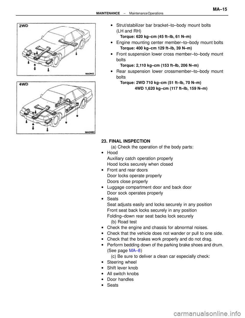
wSeatswStrut/stabilizer bar bracket±to±body mount bolts
(LH and RH)
Torque: 620 kg±cm (45 ft±lb, 61 N±m)
wEngine mounting center member±to±body mount bolts
Torque: 400 kg±cm 129 ft±lb, 39 N±m)
wFront suspension lower cross member±to±body mount
bolts
Torque: 2,110 kg±cm (153 ft±Ib, 206 N±m)
wRear suspension lower crossmember±to±body mount
bolts
Torque: 2WD 710 kg±cm (51 ft±lb, 70 N±m)
4WD 1,620 kg±cm (117 ft±Ib, 159 N±m)
± MAINTENANCEMaintenance OperationsMA±15
Page 2302 of 2389
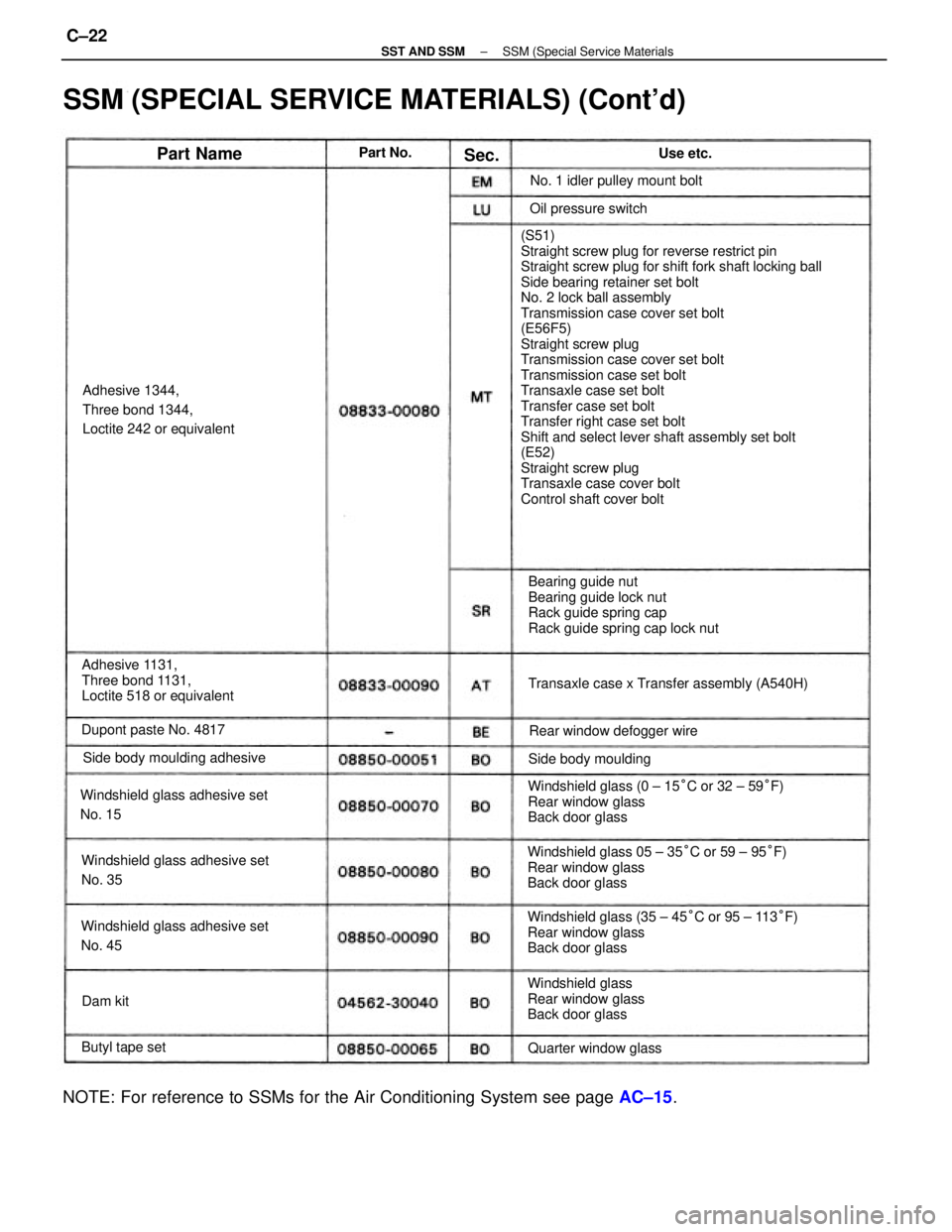
(S51)
Straight screw plug for reverse restrict pin
Straight screw plug for shift fork shaft locking ball
Side bearing retainer set bolt
No. 2 lock ball assembly
Transmission case cover set bolt
(E56F5)
Straight screw plug
Transmission case cover set bolt
Transmission case set bolt
Transaxle case set bolt
Transfer case set bolt
Transfer right case set bolt
Shift and select lever shaft assembly set bolt
(E52)
Straight screw plug
Transaxle case cover bolt
Control shaft cover bolt
SSM (SPECIAL SERVICE MATERIALS) (Cont'd)
Windshield glass (35 ± 45°C or 95 ± 113°F)
Rear window glass
Back door glass Windshield glass 05 ± 35°C or 59 ± 95°F)
Rear window glass
Back door glassWindshield glass (0 ± 15°C or 32 ± 59°F)
Rear window glass
Back door glass
NOTE: For reference to SSMs for the Air Conditioning System see page AC±15.
Bearing guide nut
Bearing guide lock nut
Rack guide spring cap
Rack guide spring cap lock nut
Adhesive 1131,
Three bond 1131,
Loctite 518 or equivalentAdhesive 1344,
Three bond 1344,
Loctite 242 or equivalent
Windshield glass adhesive set
No. 15
Windshield glass adhesive set
No. 45Windshield glass adhesive set
No. 35Transaxle case x Transfer assembly (A540H)
Windshield glass
Rear window glass
Back door glass Side body moulding adhesiveNo. 1 idler pulley mount bolt
Rear window defogger wire Dupont paste No. 4817
Quarter window glassSide body mouldingOil pressure switch
Butyl tape set
Part NameUse etc. Part No.
Dam kitSec.
± SST AND SSMSSM (Special Service MaterialsC±22