Page 1867 of 2389
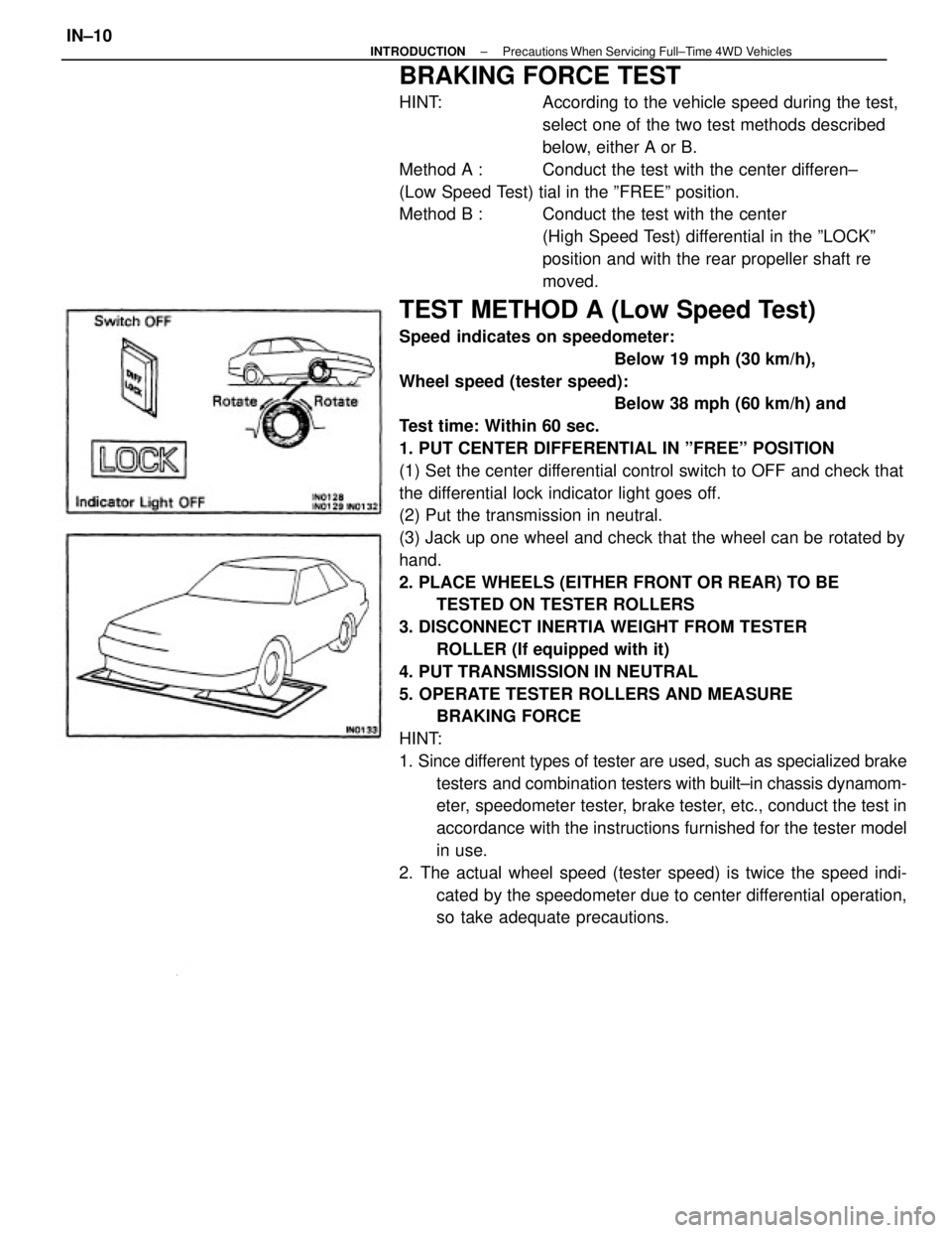
BRAKING FORCE TEST
HINT: According to the vehicle speed during the test,
select one of the two test methods described
below, either A or B.
Method A : Conduct the test with the center differen±
(Low Speed Test) tial in the ºFREEº position.
Method B : Conduct the test with the center
(High Speed Test) differential in the ºLOCKº
position and with the rear propeller shaft re
moved.
TEST METHOD A (Low Speed Test)
Speed indicates on speedometer:
Below 19 mph (30 km/h),
Wheel speed (tester speed):
Below 38 mph (60 km/h) and
Test time: Within 60 sec.
1. PUT CENTER DIFFERENTIAL IN ºFREEº POSITION
(1) Set the center differential control switch to OFF and check that
the differential lock indicator light goes off.
(2) Put the transmission in neutral.
(3) Jack up one wheel and check that the wheel can be rotated by
hand.
2. PLACE WHEELS (EITHER FRONT OR REAR) TO BE
TESTED ON TESTER ROLLERS
3. DISCONNECT INERTIA WEIGHT FROM TESTER
ROLLER (If equipped with it)
4. PUT TRANSMISSION IN NEUTRAL
5. OPERATE TESTER ROLLERS AND MEASURE
BRAKING FORCE
HINT:
1. Since different types of tester are used, such as specialized brake
testers and combination testers with built±in chassis dynamom-
eter, speedometer tester, brake tester, etc., conduct the test in
accordance with the instructions furnished for the tester model
in use.
2. The actual wheel speed (tester speed) is twice the speed indi-
cated by the speedometer due to center differential operation,
so take adequate precautions.
± INTRODUCTIONPrecautions When Servicing Full±Time 4WD VehiclesIN±10
Page 1868 of 2389
![TOYOTA CAMRY V20 1986 Service Information TEST METHOD B (High Speed Test)
[Vehicle speed: Over 38 mph (60 km/h)]
1. PUT CENTER DIFFERENTIAL IN ºLOCKº POSITION
(1) Set the center differential control switch to ON and
check that the different TOYOTA CAMRY V20 1986 Service Information TEST METHOD B (High Speed Test)
[Vehicle speed: Over 38 mph (60 km/h)]
1. PUT CENTER DIFFERENTIAL IN ºLOCKº POSITION
(1) Set the center differential control switch to ON and
check that the different](/manual-img/14/57449/w960_57449-1867.png)
TEST METHOD B (High Speed Test)
[Vehicle speed: Over 38 mph (60 km/h)]
1. PUT CENTER DIFFERENTIAL IN ºLOCKº POSITION
(1) Set the center differential control switch to ON and
check that the differential lock indicator light goes on.
HINT: If the indicator light does not go on when the
center differential control switch is turned on, move
the vehicle backward or forward slightly.
(2) Put the transmission in neutral.
(3) Jack up one wheel and check that the wheel cannot be
rotated by hand.
2. REMOVE REAR PROPELLER SHAFT
Make matching marks on each end of the rear propeller
shaft, then remove it.
3. PLACE WHEELS (EITHER FRONT OR REAR) TO BE
TESTED ON TESTER ROLLERS
4. DISCONNECT INERTIA WEIGHT FROM TESTER\ROLL-
ER (If equipped with it)
5. PUT TRANSMISSION IN NEUTRAL
6. OPERATE TESTER ROLLERS AND MEASURE
BRAKING FORCE
HINT: Since different types of tester are used, such as spe-
cialized brake testers and combination testers with
built±in chassis dynamometer, speedometer tester, brake
tester, etc., conduct the test in accordance with the instruc-
tions furnished for± the tester model in use.
7. INSTALL REAR PROPELLER SHAFT
Align the matching marks made on the rear propeller shaft
before removal, then install it.
8. SET CENTER DIFFERENTIAL CONTROL SWITCH TO
OFF
NOTE: If the indicator light does not go off when the center
differential control switch is turned off, move the vehicle
backward or forward slightly and check that the indicator light
goes off.
± INTRODUCTIONPrecautions When Servicing Full±Time 4WD VehiclesIN±11
Page 1869 of 2389
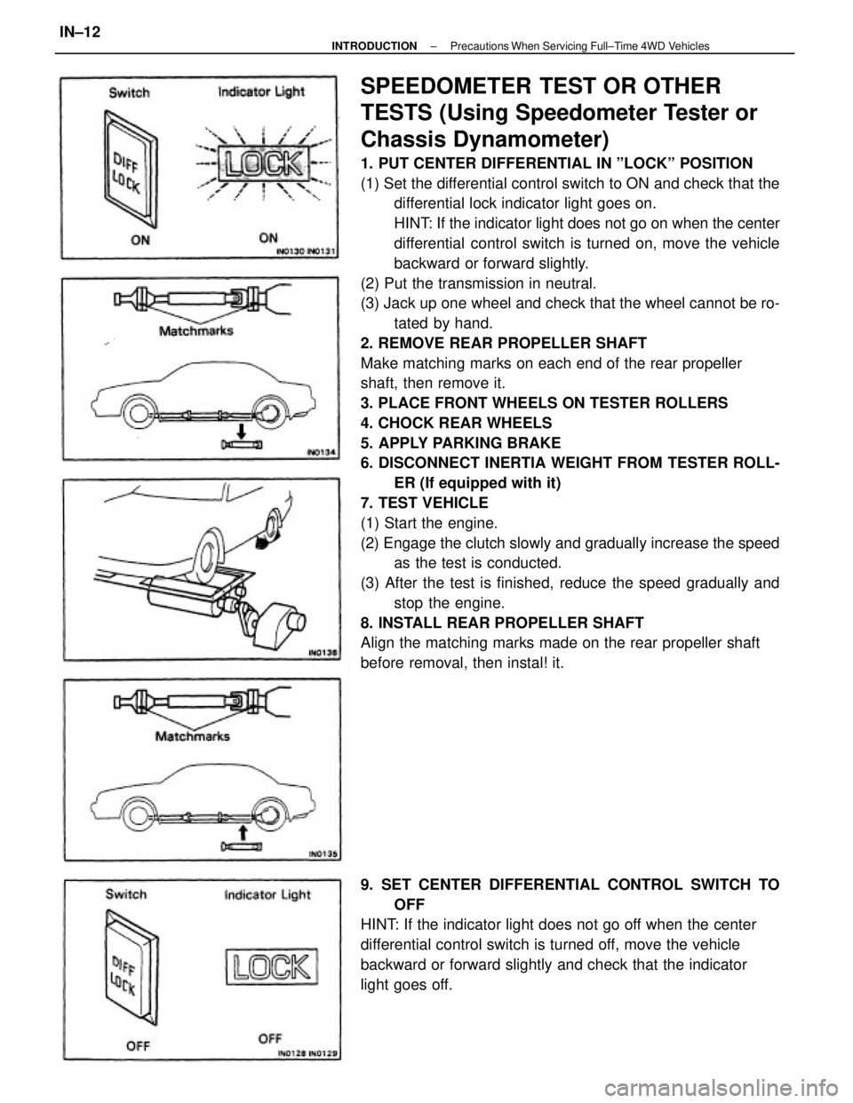
SPEEDOMETER TEST OR OTHER
TESTS (Using Speedometer Tester or
Chassis Dynamometer)
1. PUT CENTER DIFFERENTIAL IN ºLOCKº POSITION
(1) Set the differential control switch to ON and check that the
differential lock indicator light goes on.
HINT: If the indicator light does not go on when the center
differential control switch is turned on, move the vehicle
backward or forward slightly.
(2) Put the transmission in neutral.
(3) Jack up one wheel and check that the wheel cannot be ro-
tated by hand.
2. REMOVE REAR PROPELLER SHAFT
Make matching marks on each end of the rear propeller
shaft, then remove it.
3. PLACE FRONT WHEELS ON TESTER ROLLERS
4. CHOCK REAR WHEELS
5. APPLY PARKING BRAKE
6. DISCONNECT INERTIA WEIGHT FROM TESTER ROLL-
ER (If equipped with it)
7. TEST VEHICLE
(1) Start the engine.
(2) Engage the clutch slowly and gradually increase the speed
as the test is conducted.
(3) After the test is finished, reduce the speed gradually and
stop the engine.
8. INSTALL REAR PROPELLER SHAFT
Align the matching marks made on the rear propeller shaft
before removal, then instal! it.
9. SET CENTER DIFFERENTIAL CONTROL SWITCH TO
OFF
HINT: If the indicator light does not go off when the center
differential control switch is turned off, move the vehicle
backward or forward slightly and check that the indicator
light goes off.
± INTRODUCTIONPrecautions When Servicing Full±Time 4WD VehiclesIN±12
Page 1875 of 2389
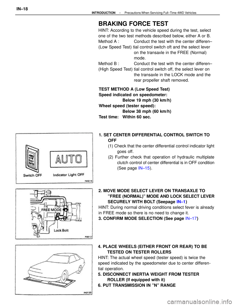
BRAKING FORCE TEST
HINT: According to the vehicle speed during the test, select
one of the two test methods described below, either A or B.
Method A : Conduct the test with the center differen±
(Low Speed Test) tial control switch oft and the select lever
on the transaxle in the FREE (Normal)
mode.
Method B : Conduct the test with the center differen±
(High Speed Test) tial control switch off, the select lever on
the transaxle in the LOCK mode and the
rear propeller shaft removed.
4. PLACE WHEELS (EITHER FRONT OR REAR) TO BE
TESTED ON TESTER ROLLERS
HINT: The actual wheel speed (tester speed) is twice the
speed indicated by the speedometer due to center differen-
tial operation.
5. DISCONNECT INERTIA WEIGHT FROM TESTER
ROLLER (If equipped with it)
6. PUT TRANSMISSION IN ºNº RANGE1. SET CENTER DIFFERENTIAL CONTROL SWITCH TO
OFF
(1) Check that the center differential control indicator light
goes off.
(2) Further check that operation of hydraulic multiplate
clutch control of center differential is in OFF condition
(See page IN±15).
2. MOVE MODE SELECT LEVER ON TRANSAXLE TO
ºFREE (NORMAL)º MODE AND LOCK SELECT LEVER
SECURELY WITH BOLT (Seepage IN±1)
HINT: During normal driving conditions select fever is already
in FREE mode so there is no need to change it.
3. CONFIRM MODE SELECTION (See page IN±17) TEST METHOD A (Low Speed Test)
Speed indicated on speedometer:
Below 19 mph (30 km/h)
Wheel speed (tester speed):
Below 38 mph (60 km/h)
Test time: Within 60 sec.
± INTRODUCTIONPrecautions When Servicing Full±Time 4WD VehiclesIN±18
Page 1877 of 2389
5. PLACE WHEELS (EITHER FRONT OR REAR) TO BE
TESTED ON TESTER ROLLERS
6. CHOCK OTHER WHEELS
7. DISCONNECT INERTIA WEIGHT FROM TESTER ROLL-
ER (if equipped with it)
8. PUT TRANSMISSION IN N RANGE
9. OPERATE TESTER ROLLERS AND MEASURE
BRAKING FORCE WITH ENGINE AT IDLE
HINT: Since different types of tester are used, such as
specialized brake testers and combination testers with
builtin chassis dynamometer, speedometer tester, brake test-
er, etc., conduct the test in accordance with the instructions
furnished for the tester in use.
10. AFTER FINISHING TEST, INSTAL! REAR PROPELLER
SHAFT
Align the matching marks made on the rear propeller shaft
before removal, then install it.
11. RETURN MODE SELECT LEVER TO ºFREE (NORMAL)º
MODE POSITION AND LOCK IT SECURELY WITH
BOLT
12. SET CENTER DIFFERENTIAL CONTROL SWITCH TO
AUTO
± INTRODUCTIONPrecautions When Servicing Full±Time 4WD VehiclesIN±20
Page 1878 of 2389
![TOYOTA CAMRY V20 1986 Service Information SPEEDOMETER TEST OR OTHER TESTS
[Using Speedometer Tester or Chassis Dynamometer]
1. SET CENTER DIFFERENTIAL CONTROL SWITCH TO
OFF
(1) Check that the center differential control indicator light
goes TOYOTA CAMRY V20 1986 Service Information SPEEDOMETER TEST OR OTHER TESTS
[Using Speedometer Tester or Chassis Dynamometer]
1. SET CENTER DIFFERENTIAL CONTROL SWITCH TO
OFF
(1) Check that the center differential control indicator light
goes](/manual-img/14/57449/w960_57449-1877.png)
SPEEDOMETER TEST OR OTHER TESTS
[Using Speedometer Tester or Chassis Dynamometer]
1. SET CENTER DIFFERENTIAL CONTROL SWITCH TO
OFF
(1) Check that the center differential control indicator light
goes oft.
(2) Further check that the operation of the hydraulic
multiplate clutch control of the center differential is in
OFF condition.
(See page IN±15)
2. MOVE MODE SELECT LEVER ON TRANSAXLE TO ºLOCKº
MODE AND LOCK IT SECURELY WITH BOLT (See page
IN±16)
3. CONFIRM MODE SELECTION
(See page IN±17)
8. DISCONNECT INERTIA WEIGHT FROM TESTER ROLL-
ER (If equipped with it)
9. TEST VEHICLE
(1) Start the engine.
(2) Put the transmission in D range, then gradually in-
crease the speed as the test in conducted.
(3) After the test is finished, reduce the speed gradually
and stop the engine. 4. REMOVE REAR PROPELLER SHAFT
Make matching marks on each end of the rear propeller
shaft, then remove it.
5. PLACE FRONT WHEELS ON TESTER ROLLERS
6. CHOCK REAR WHEELS
7. APPLY PARKING BRAKE
10. AFTER FINISHING TEST, INSTALL REAR PROPELLER
SHAFT
Align the matching marks made on the rear propeller shaft
before removal, then install it.
± INTRODUCTIONPrecautions When Servicing Full±Time 4WD VehiclesIN±21
Page 1897 of 2389
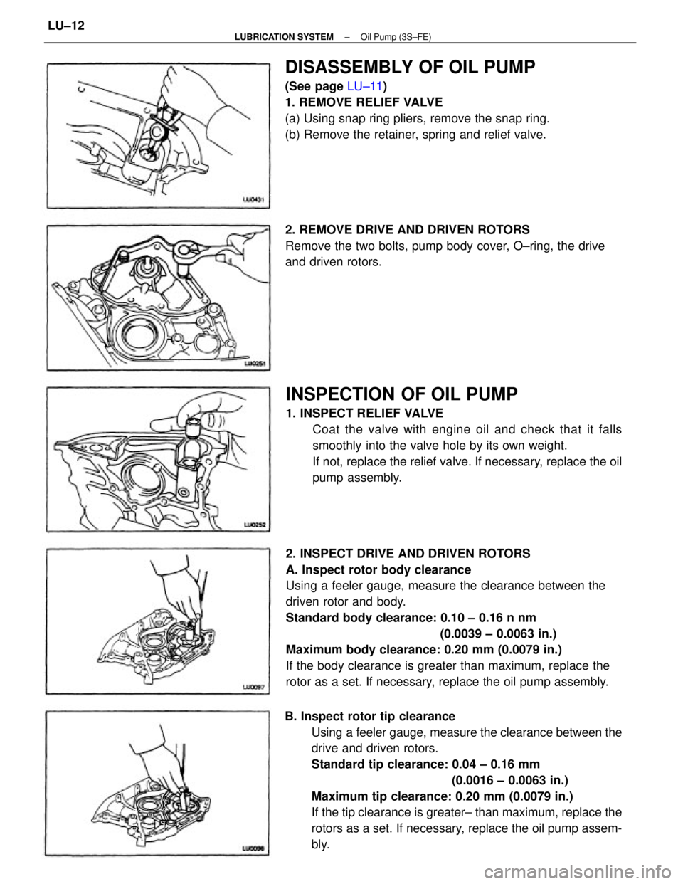
2. INSPECT DRIVE AND DRIVEN ROTORS
A. Inspect rotor body clearance
Using a feeler gauge, measure the clearance between the
driven rotor and body.
Standard body clearance: 0.10 ± 0.16 n nm
(0.0039 ± 0.0063 in.)
Maximum body clearance: 0.20 mm (0.0079 in.)
If the body clearance is greater than maximum, replace the
rotor as a set. If necessary, replace the oil pump assembly.
B. Inspect rotor tip clearance
Using a feeler gauge, measure the clearance between the
drive and driven rotors.
Standard tip clearance: 0.04 ± 0.16 mm
(0.0016 ± 0.0063 in.)
Maximum tip clearance: 0.20 mm (0.0079 in.)
If the tip clearance is greater± than maximum, replace the
rotors as a set. If necessary, replace the oil pump assem-
bly.
INSPECTION OF OIL PUMP
1. INSPECT RELIEF VALVE
Coat the valve with engine oil and check that it falls
smoothly into the valve hole by its own weight.
If not, replace the relief valve. If necessary, replace the oil
pump assembly.
DISASSEMBLY OF OIL PUMP
(See page LU±11)
1. REMOVE RELIEF VALVE
(a) Using snap ring pliers, remove the snap ring.
(b) Remove the retainer, spring and relief valve.
2. REMOVE DRIVE AND DRIVEN ROTORS
Remove the two bolts, pump body cover, O±ring, the drive
and driven rotors.
± LUBRICATION SYSTEMOil Pump (3S±FE)LU±12
Page 1905 of 2389
Standard side clearance: 0.030 ± 0.090 mm
(0.0012 ± 0.0035 in.)
Maximum side clearance: 0.15 mm (0.0059 in.)
If the side clearance is greater than maximum, replace the
rotors as a set. If necessary, replace the oil pump assembly.
C. Inspect rotor tip clearance
Using a feeler gauge, measure the clearance between the
drive and driven rotors.
Standard tip clearance: 0.110 ± 0.240 mm
(0.0043 ± 0.0094 in.)
Maximum tip clearance: 0.35 mm (0.0138 in.)
If the tip clearance is greater than maximum, replace the
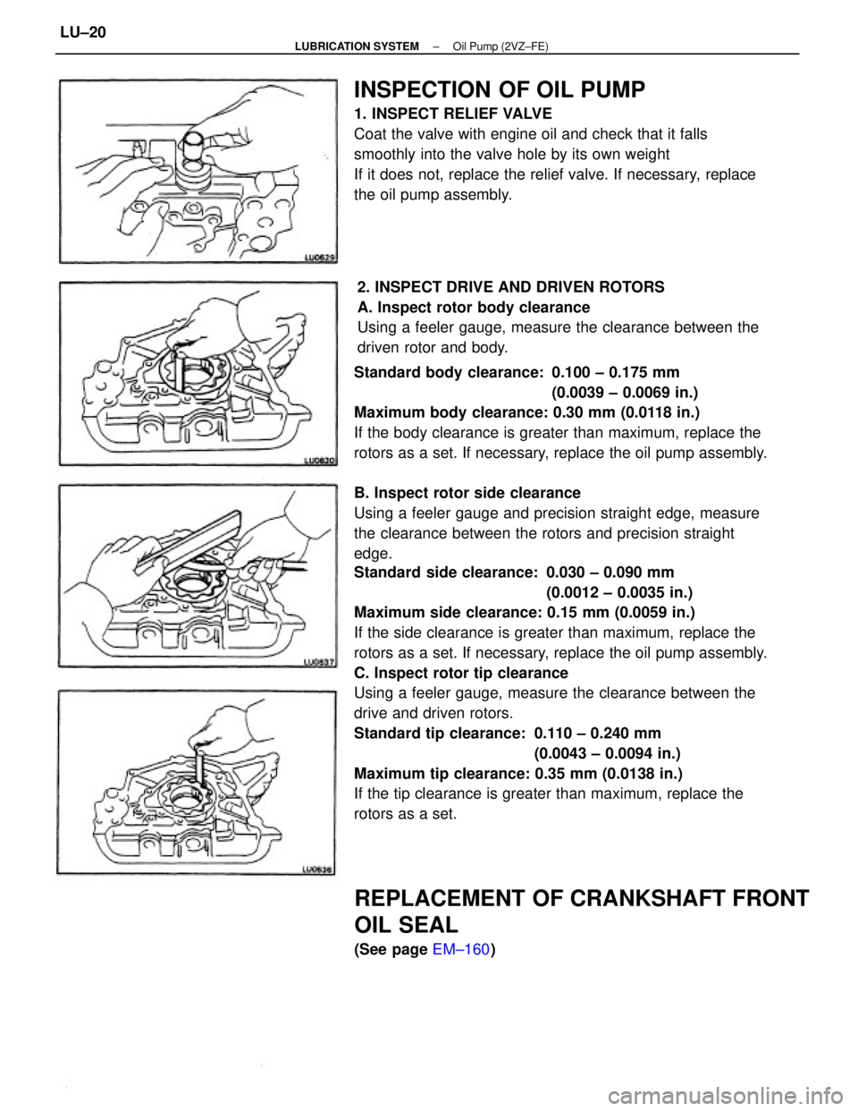
rotors as a set. Standard body clearance: 0.100 ± 0.175 mm
(0.0039 ± 0.0069 in.)
Maximum body clearance: 0.30 mm (0.0118 in.)
If the body clearance is greater than maximum, replace the
rotors as a set. If necessary, replace the oil pump assembly.
B. Inspect rotor side clearance
Using a feeler gauge and precision straight edge, measure
the clearance between the rotors and precision straight
edge.
INSPECTION OF OIL PUMP
1. INSPECT RELIEF VALVE
Coat the valve with engine oil and check that it falls
smoothly into the valve hole by its own weight
If it does not, replace the relief valve. If necessary, replace
the oil pump assembly.
2. INSPECT DRIVE AND DRIVEN ROTORS
A. Inspect rotor body clearance
Using a feeler gauge, measure the clearance between the
driven rotor and body.
REPLACEMENT OF CRANKSHAFT FRONT
OIL SEAL
(See page EM±160)
± LUBRICATION SYSTEMOil Pump (2VZ±FE)LU±20