Page 1254 of 2389

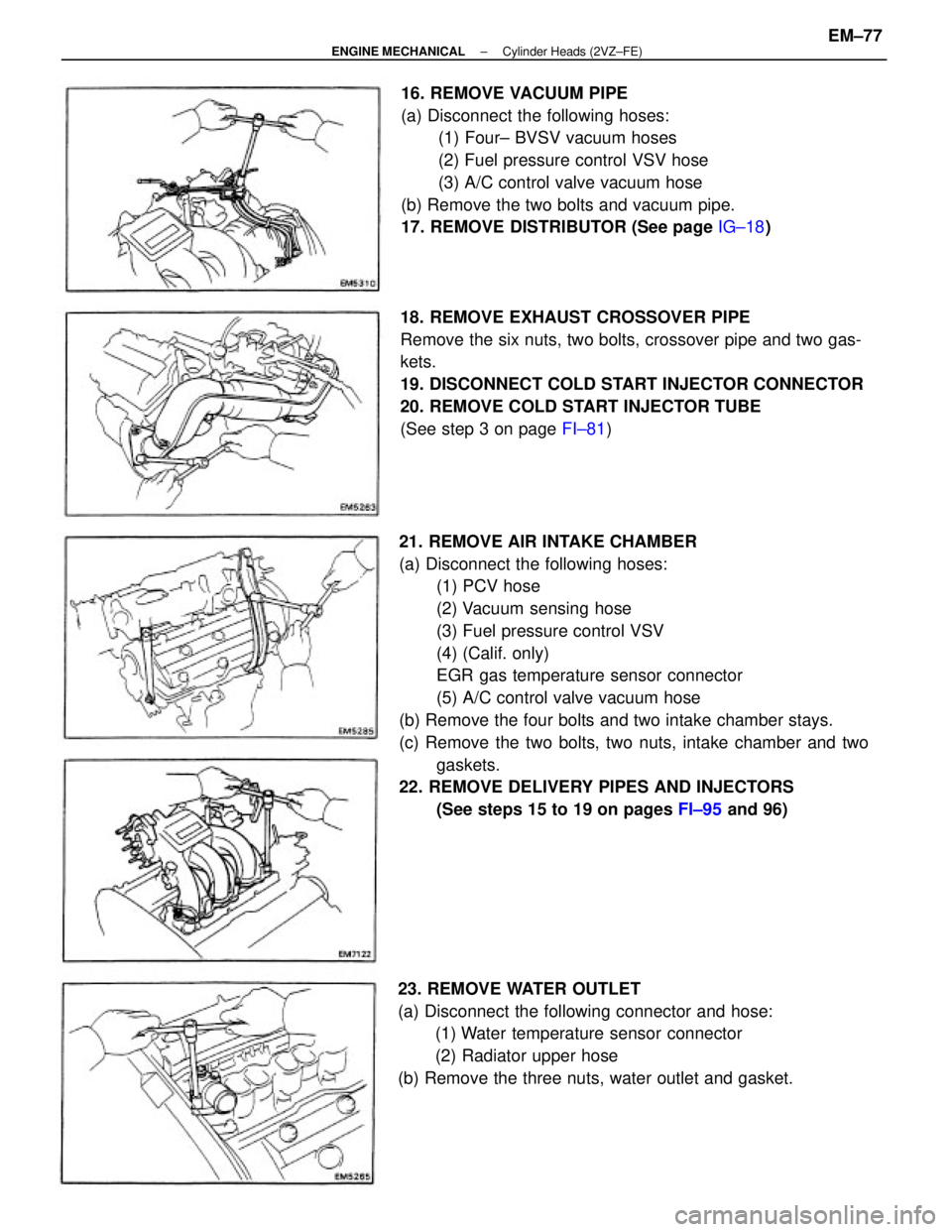
21. REMOVE AIR INTAKE CHAMBER
(a) Disconnect the following hoses:
(1) PCV hose
(2) Vacuum sensing hose
(3) Fuel pressure control VSV
(4) (Calif. only)
EGR gas temperature sensor connector
(5) A/C control valve vacuum hose
(b) Remove the four bolts and two intake chamber stays.
(c) Remove the two bolts, two nuts, intake chamber and two
gaskets.
22. REMOVE DELIVERY PIPES AND INJECTORS
(See steps 15 to 19 on pages FI±95 and 96) 18. REMOVE EXHAUST CROSSOVER PIPE
Remove the six nuts, two bolts, crossover pipe and two gas-
kets.
19. DISCONNECT COLD START INJECTOR CONNECTOR
20. REMOVE COLD START INJECTOR TUBE
(See step 3 on page FI±81) 16. REMOVE VACUUM PIPE
(a) Disconnect the following hoses:
(1) Four± BVSV vacuum hoses
(2) Fuel pressure control VSV hose
(3) A/C control valve vacuum hose
(b) Remove the two bolts and vacuum pipe.
17. REMOVE DISTRIBUTOR (See page IG±18)
23. REMOVE WATER OUTLET
(a) Disconnect the following connector and hose:
(1) Water temperature sensor connector
(2) Radiator upper hose
(b) Remove the three nuts, water outlet and gasket.
± ENGINE MECHANICALCylinder Heads (2VZ±FE)EM±77
Page 1255 of 2389
24. REMOVE WATER BY±PASS OUTLET
(a) Disconnect the following connectors and hose:
(1) Cold start injector time switch connector
(2) Water temperature sensor connector
(3) Heater water by±pass hose
(b) Remove the three nuts, water by±pass outlet and gasket.
(c) Remove the two bolts and crossover pipe heat insulator
from the water by±pass outlet.
25. REMOVE CYLINDER HEAD REAR PLATE
Remove the two bolts and rear plate.
27. REMOVE RH EXHAUST MANIFOLD
(a) Disconnect the oxygen sensor connector.
(b) Remove the three. nuts and outside heat insulator. 26. REMOVE INTAKE MANIFOLD
(a) Remove the two bolts and No.2 idler pulley bracket stay.
(b) Remove the eight bolts, four nuts, intake manifold and
two gaskets.
± ENGINE MECHANICALCylinder Heads (2VZ±FE)EM±78
Page 1280 of 2389
13. INSTALL LH EXHAUST MANIFOLD
(a) Install a new gasket and the exhaust manifold with new six
nuts.
Torque: 400 kg±cm (29 ft±Ib, 39 N±m)
12. INSTALL INTAKE MANIFOLD
(a) Install two new gaskets and the intake manifold with the
eight bolts and four nuts.
Torque: 180 kg±cm (13 ft±Ib, 18 N±m)
(b) Install a new gasket and the exhaust manifold with new
six nuts.
Torque: 400 kg±cm (29 ft±Ib, 39 N±m)
(c) Install the outside heat insulator with the three nuts.
(d) Connect the oxygen sensor connector.
(b) Install the heat insulator with the two nuts.
± ENGINE MECHANICALCylinder Heads (2VZ±FE)EM±103
Page 1281 of 2389
16. INSTALL WATER OUTLET
(a) Connect the following hose and connector:
(1) Radiator upper hose
(2)Water temperature sensor connector
(b) Install a new gasket and the water outlet with the three nuts.
Torque: 85 kg±cm (73 in.±Ib, 8.3 N±m)
17. INSTALL INJECTORS AND DELIVERY PIPES
(See steps 1 to 5 on pages FI±98 and 99) (b) Install a new gasket and the water by±pass outlet with
the three nuts.
Torque: 200 kg±cm (14 ft±tb, 20 N±m)
(c) Connect the following connectors and hose:
(1) Heater water by±pass hose
(2) Cold start injector time switch connector
(3) Water temperature switch 15. INSTALL WATER BY±PASS OUTLET
(a) Install the crossover pipe heat insulator with the two bolts. (b) Install the No.2 idler pulley bracket stay with the two
bolts.
Torque: 185 kg±cm (13 ft±tb. 18 N±m)
14. INSTALL CYLINDER HEAD REAR PLATE
Install the rear plate with the two bolts.
± ENGINE MECHANICALCylinder Heads (2VZ±FE)EM±104
Page 1282 of 2389

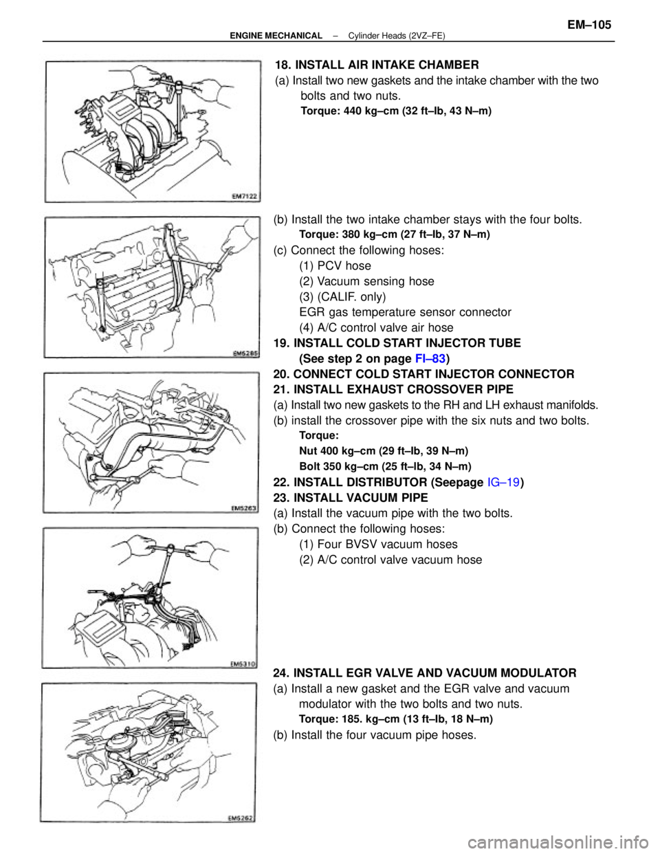
(b) Install the two intake chamber stays with the four bolts.
Torque: 380 kg±cm (27 ft±Ib, 37 N±m)
(c) Connect the following hoses:
(1) PCV hose
(2) Vacuum sensing hose
(3) (CALIF. only)
EGR gas temperature sensor connector
(4) A/C control valve air hose
19. INSTALL COLD START INJECTOR TUBE
(See step 2 on page FI±83)
20. CONNECT COLD START INJECTOR CONNECTOR
21. INSTALL EXHAUST CROSSOVER PIPE
(a) Install two new gaskets to the RH and LH exhaust manifolds.
(b) install the crossover pipe with the six nuts and two bolts.
Torque:
Nut 400 kg±cm (29 ft±Ib, 39 N±m)
Bolt 350 kg±cm (25 ft±lb, 34 N±m)
22. INSTALL DISTRIBUTOR (Seepage IG±19)
23. INSTALL VACUUM PIPE
(a) Install the vacuum pipe with the two bolts.
(b) Connect the following hoses:
(1) Four BVSV vacuum hoses
(2) A/C control valve vacuum hose
24. INSTALL EGR VALVE AND VACUUM MODULATOR
(a) Install a new gasket and the EGR valve and vacuum
modulator with the two bolts and two nuts.
Torque: 185. kg±cm (13 ft±Ib, 18 N±m)
(b) Install the four vacuum pipe hoses.18. INSTALL AIR INTAKE CHAMBER
(a) Install two new gaskets and the intake chamber with the two
bolts and two nuts.
Torque: 440 kg±cm (32 ft±Ib, 43 N±m)
± ENGINE MECHANICALCylinder Heads (2VZ±FE)EM±105
Page 1323 of 2389
PREPARATION FOR DISASSEMBLY
1. (M/T)
REMOVE CLUTCH COVER AND DISC
2. (M/T)
REMOVE FLYWHEEL
3. (A/T)
REMOVE DRIVE PLATE
4 REMOVE REAR END PLATE
Remove the bolt and end plate.
5. INSTALL ENGINE TO ENGINE STAND FOR
DISASSEMBLY
6. REMOVE DISTRIBUTOR (See page IG±18)
7. REMOVE TIMING BELT AND PULLEYS
(See page EM±34)
8. REMOVE CYLINDER HEADS (See page EM±76)
9. REMOVE WATER PUMP (See page CO±9)
10. REMOVE OIL PAN AND OIL PUMP
(See page LU±17)
11. REMOVE OIL FILTER (See page LU±7)
12. REMOVE KNOCK SENSOR
Using SST, remove the knock sensor.
SST 09816±30010
13. REMOVE WATER BY±PASS PIPE
Remove the two bolts, two nuts and by±pass pipe.
14. REMOVE NO.2 IDLER PULLEY BRACKET
Remove the three bolts and mounting bracket.
± ENGINE MECHANICALCylinder Block (2VZ±FE)EM±146
Page 1344 of 2389

2. INSTALL WATER BY±PASS PIPE
(a) Remove any old packing (FIPG) material and be careful not
to drop any oil on the contact surfaces of the bypass pipe
and cylinder block.
wUsing a razor blade and gasket scraper, remove all the old
packing (FIPG) material from the gasket surfaces and seal-
ing groove.
wThoroughly clean all components to remove all the loose
material.
wUsing a non±residue solvent, clean both sealing surfaces.
(b) Apply seal packing to the groove of the by±pass pipe.
Seal packing: Part No. 08826±00100 or equivalent
wInstall a nozzle that has been cut to a 2 ± 3 mm
(0.08 0.12 in.) opening.
HINT: Avoid applying an excessive amount to the surface.
wParts must be assembled within 5 minutes of application.
Otherwise the material must be removed and reapplied.
wImmediately remove nozzle from the tube and reinstall cap.
(c) Install the by±pass pipe with the two bolts and two nuts.
Torque: 85 kg±cm (74 in.±lb, 8.3 N±m)
POST ASSEMBLY
1. INSTALL NO. 2 IDLER PULLEY BRACKET
Install the pulley bracket with the three bolts. Torque the
bolts.
Torque: 380 kg±cm (27 ft±Ib, 37 N±m)
3. INSTALL KNOCK SENSOR
Using SST, install the knock sensor.
SST 09816±30010
Torque: 450 kg±cm (33 ft±lb, 44 N±m)
± ENGINE MECHANICALCylinder Block (2VZ±FE)EM±167
Page 1837 of 2389
ELECTRONIC SPARK ADVANCE (ESA)
The ECU is programmed with data for optimum ignition timing
under any and all operating conditions. Using data provided
by sensors which monitor various engine functions (rpm, in-
take air volume, eng. temperature, etc.) the microcomputer
(ECU) triggers the spark at precisely the right instant.
IGNITION SYSTEM CIRCUIT
± IGNITION SYSTEMIgnition System CircuitIG±4