Page 1145 of 2389
Sub±Oxygen Sensor (CALIF. only)
INSPECTION OF SUB±OXYGEN
SENSOR
INSPECT SUB±OXYGEN SENSOR
HINT: Inspect only when code No.27 is displayed.
(a) Diagnostic code cancellation.
(See page FI±24)
(b) Warm up the engine until it reaches normal operating
temperature.
(a) (M/T)
Drive for 5 minutes or more between 80 km/h (50
mph) and 100 km/h in 4th or 5th gear.
(A/T)
Drive for 5 minutes or more between 80 km/h (50
mph) and 100 km/h (62 mph) in ºDº range.
(d) Following the conditions in step (e), press fully on the
accelerator pedal for 2 seconds or more.
HINT: Do not exceed 100 km/h (62 mph), or diagnostic code
will be cancelled.
(e) Stop the vehicle and turn the ignition switch to OFF.
(f) Carry out steps (b), (c) and (d) again to test acceleration.
If code No. 27 reappears again, check the sub±oxygen sensor
circuit. If the circuit is normal, replace the suboxygen sen-
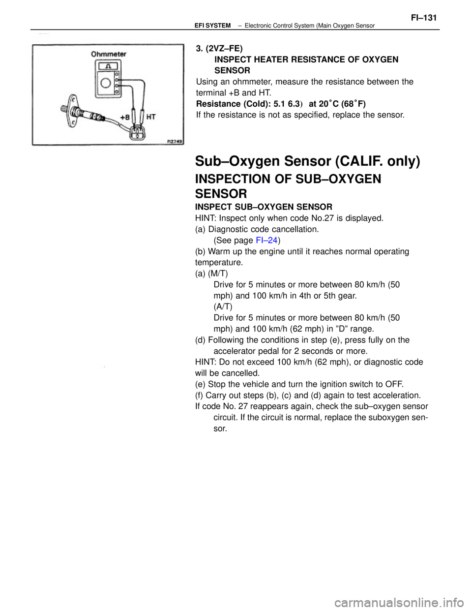
sor. 3. (2VZ±FE)
INSPECT HEATER RESISTANCE OF OXYGEN
SENSOR
Using an ohmmeter, measure the resistance between the
terminal +B and HT.
Resistance (Cold): 5.1 6.3� at 20°C (68°F)
If the resistance is not as specified, replace the sensor.
± EFI SYSTEMElectronic Control System (Main Oxygen SensorFI±131
Page 1146 of 2389
Sub±Oxygen Sensor (CALIF. only)
INSPECTION OF SUB±OXYGEN
SENSOR
INSPECT SUB±OXYGEN SENSOR
HINT: Inspect only when code No.27 is displayed.
(a) Diagnostic code cancellation.
(See page FI±24)
(b) Warm up the engine until it reaches normal operating
temperature.
(a) (M/T)
Drive for 5 minutes or more between 80 km/h (50
mph) and 100 km/h in 4th or 5th gear.
(A/T)
Drive for 5 minutes or more between 80 km/h (50
mph) and 100 km/h (62 mph) in ºDº range.
(d) Following the conditions in step (e), press fully on the
accelerator pedal for 2 seconds or more.
HINT: Do not exceed 100 km/h (62 mph), or diagnostic code
will be cancelled.
(e) Stop the vehicle and turn the ignition switch to OFF.
(f) Carry out steps (b), (c) and (d) again to test acceleration.
If code No. 27 reappears again, check the sub±oxygen sensor
circuit. If the circuit is normal, replace the suboxygen sen-
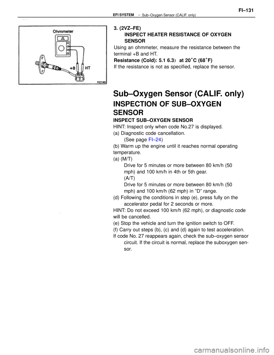
sor. 3. (2VZ±FE)
INSPECT HEATER RESISTANCE OF OXYGEN
SENSOR
Using an ohmmeter, measure the resistance between the
terminal +B and HT.
Resistance (Cold): 5.1 6.3� at 20°C (68°F)
If the resistance is not as specified, replace the sensor.
± EFI SYSTEM
Sub±Oxygen Sensor (CALIF. only)FI±131
Page 1152 of 2389
Fuel Cut RPM
INSPECTION OF FUEL CUT RPM
1. WARM UP ENGINE
Allow the engine to warm up to normal operating temperature.
2. INSPECT FUEL CUT RPM
(a) Disconnect the connector from the throttle position sensor.
(b) Connect terminals IDL and E1 (3S±FE (w/o ECT)) or E2
(others) of the wiring connector.
(e) Gradually raise the engine rpm and check that there is fluctua-
tion between the fuel cut and fuel return points.
HINT:
wThe vehicle should be stopped.
wMeasure with the A/C OFF.
Fuel cut rpm: 3S±FE 1,500 ± 2,100 rpm
2VZ±FE 1,800 rpm
Fuel return rpm: 3S±FE 1,000 rpm
2VZ±FE 1,200 rpm
± EFI SYSTEMElectronic Control System (Fuel Cut RPM)FI±137
Page 1198 of 2389
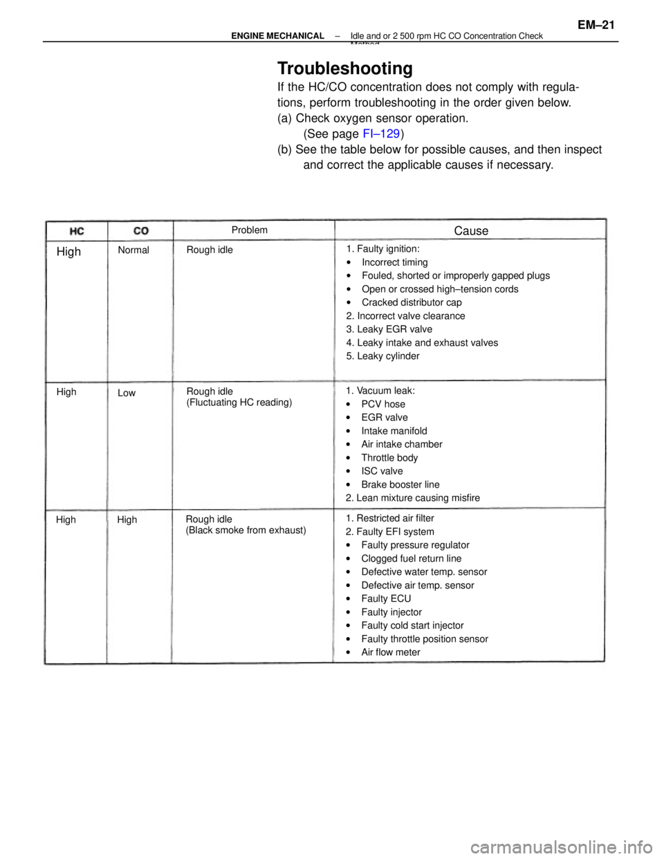
Troubleshooting
If the HC/CO concentration does not comply with regula-
tions, perform troubleshooting in the order given below.
(a) Check oxygen sensor operation.
(See page FI±129)
(b) See the table below for possible causes, and then inspect
and correct the applicable causes if necessary.
1. Faulty ignition:
wIncorrect timing
wFouled, shorted or improperly gapped plugs
wOpen or crossed high±tension cords
wCracked distributor cap
2. Incorrect valve clearance
3. Leaky EGR valve
4. Leaky intake and exhaust valves
5. Leaky cylinder
1. Restricted air filter
2. Faulty EFI system
wFaulty pressure regulator
wClogged fuel return line
wDefective water temp. sensor
wDefective air temp. sensor
wFaulty ECU
wFaulty injector
wFaulty cold start injector
wFaulty throttle position sensor
wAir flow meter 1. Vacuum leak:
wPCV hose
wEGR valve
wIntake manifold
wAir intake chamber
wThrottle body
wISC valve
wBrake booster line
2. Lean mixture causing misfire
Rough idle
(Black smoke from exhaust)Rough idle
(Fluctuating HC reading) Rough idleProblem
Normal
Cause
High
High
HighHigh
Low
± ENGINE MECHANICALIdle and or 2 500 rpm HC CO Concentration CheckMethod
EM±21
Page 1226 of 2389
REMOVAL OF CYLINDER HEAD
(See page EM±48)
1. DISCONNECT CABLE FROM NEGATIVE TERMINAL
OF BATTERY
2. DRAIN ENGINE COOLANT (See page CO±4)
3. (A/T)
DISCONNECT THROTTLE CABLE AND BRACKET FROM
THROTTLE BODY
4. DISCONNECT ACCELERATOR CABLE AND BRACKET
FROM THROTTLE BODY AND AIR INTAKE CHAMBER
5. REMOVE CRUISE CONTROL ACTUATOR
(See step 9 on page EM±108)
6. REMOVE AIR CLEANER HOSE
7. REMOVE ALTERNATOR (See page CH±6)
8. REMOVE OIL PRESSURE SWITCH, ENGINE HANGERS
AND ALTERNATOR UPPER BRACKET
9. RAISE VEHICLE
NOTICE: Be sure the vehicle is securely supported.
10. REMOVE RH FRONT WHEEL
11. REMOVE ENGINE RH UNDER COVER
12. REMOVE SUSPENSION LOWER CROSSMEMBER
(See step 20 on page EM±109)
13. DISCONNECT FRONT EXHAUST PIPE FROM
CATALYTIC CONVERTER
(See step 25 on page EM±110)
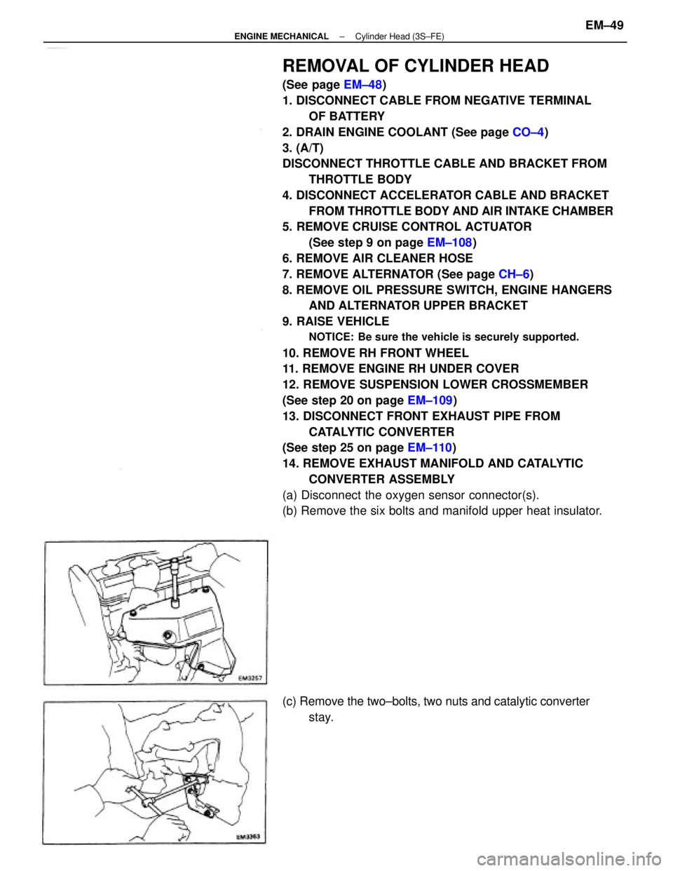
14. REMOVE EXHAUST MANIFOLD AND CATALYTIC
CONVERTER ASSEMBLY
(a) Disconnect the oxygen sensor connector(s).
(b) Remove the six bolts and manifold upper heat insulator.
(c) Remove the two±bolts, two nuts and catalytic converter
stay.
± ENGINE MECHANICALCylinder Head (3S±FE)EM±49
Page 1227 of 2389
17. REMOVE WATER OUTLET
(a) Disconnect the following connectors and hoses:
(1) Water temperature sender gauge connector
(2) Water temperature sensor connector
(3) Cold start injector time switch connector
(4) Radiator upper hose
(5) Water hoses
(6) Emission control vacuum hoses
(b) Remove the two bolts, water outlet and gasket.
18. REMOVE WATER BY±PASS PIPE
(a) Disconnect the water hoses.
(b) Remove the two bolts, two nuts, water by±pass pipe, gasket
and O±ring. 15. SEPARATE EXHAUST MANIFOLD AND CATALYTIC
CONVERTER
Remove the following parts:
(1) Five bolts
(2) Manifold lower heat insulator
(3) Eight bolts
(4) Two catalytic converter heat insulators
(5) Three bolts and two nuts
(6) Exhaust manifold
(7) Gasket
(8) Retainer
(9) Cushion
(10) Catalytic converter
16. REMOVE DISTRIBUTOR (Seepage IG±13) (d) Remove the six nuts, the exhaust manifold and catalytic
converter assembly.
± ENGINE MECHANICALCylinder Head (3S±FE)EM±50
Page 1249 of 2389
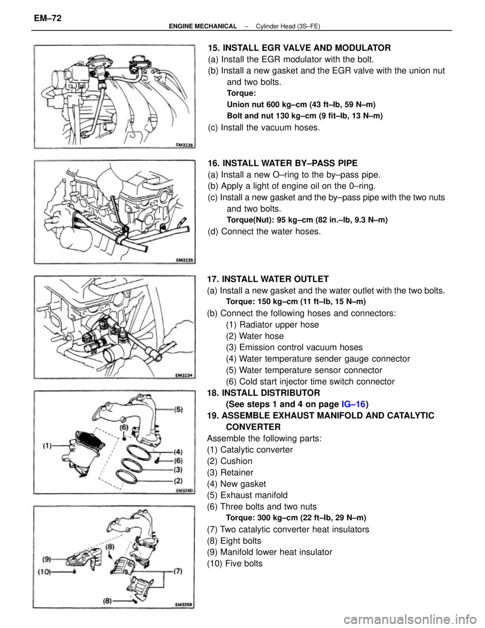
17. INSTALL WATER OUTLET
(a) Install a new gasket and the water outlet with the two bolts.
Torque: 150 kg±cm (11 ft±lb, 15 N±m)
(b) Connect the following hoses and connectors:
(1) Radiator upper hose
(2) Water hose
(3) Emission control vacuum hoses
(4) Water temperature sender gauge connector
(5) Water temperature sensor connector
(6) Cold start injector time switch connector
18. INSTALL DISTRIBUTOR
(See steps 1 and 4 on page IG±16)
19. ASSEMBLE EXHAUST MANIFOLD AND CATALYTIC
CONVERTER
Assemble the following parts:
(1) Catalytic converter
(2) Cushion
(3) Retainer
(4) New gasket
(5) Exhaust manifold
(6) Three bolts and two nuts
Torque: 300 kg±cm (22 ft±Ib, 29 N±m)
(7) Two catalytic converter heat insulators
(8) Eight bolts
(9) Manifold lower heat insulator
(10) Five bolts15. INSTALL EGR VALVE AND MODULATOR
(a) Install the EGR modulator with the bolt.
(b) Install a new gasket and the EGR valve with the union nut
and two bolts.
Torque:
Union nut 600 kg±cm (43 ft±Ib, 59 N±m)
Bolt and nut 130 kg±cm (9 fit±Ib, 13 N±m)
(c) Install the vacuum hoses.
16. INSTALL WATER BY±PASS PIPE
(a) Install a new O±ring to the by±pass pipe.
(b) Apply a light of engine oil on the 0±ring.
(c) Install a new gasket and the by±pass pipe with the two nuts
and two bolts.
Torque(Nut): 95 kg±cm (82 in.±lb, 9.3 N±m)
(d) Connect the water hoses.
± ENGINE MECHANICALCylinder Head (3S±FE)EM±72
Page 1250 of 2389
21. CONNECT FRONT EXHAUST PIPE TO CATALYTIC
CONVERTER
(See step 12 on page EM±136)
22. INSTALL SUSPENSION LOWER CROSSMEMBER
(See step 17 on page EM±136)
23. INSTALL ENGINE RH UNDER COVER
24. INSTALL RH FRONT WHEEL
25. LOWER VEHICLE(d) Install the manifold lower heat insulator with the six
bolts.
(e) Connect the oxygen sensor connector(s). (b) Install the exhaust manifold and catalytic converter as-
sembly with new six nuts.
Torque: 500 kg±cm (37 ft±Ib, 48 N±m)
20. INSTALL EXHAUST MANIFOLD AND CATALYTIC
CONVERTER ASSEMBLY
(a) Install a gasket.
(c) Install the catalytic converter stay with the two bolts and
two nuts.
± ENGINE MECHANICALCylinder Head (3S±FE)EM±73