1985 FORD GRANADA wheel
[x] Cancel search: wheelPage 149 of 255
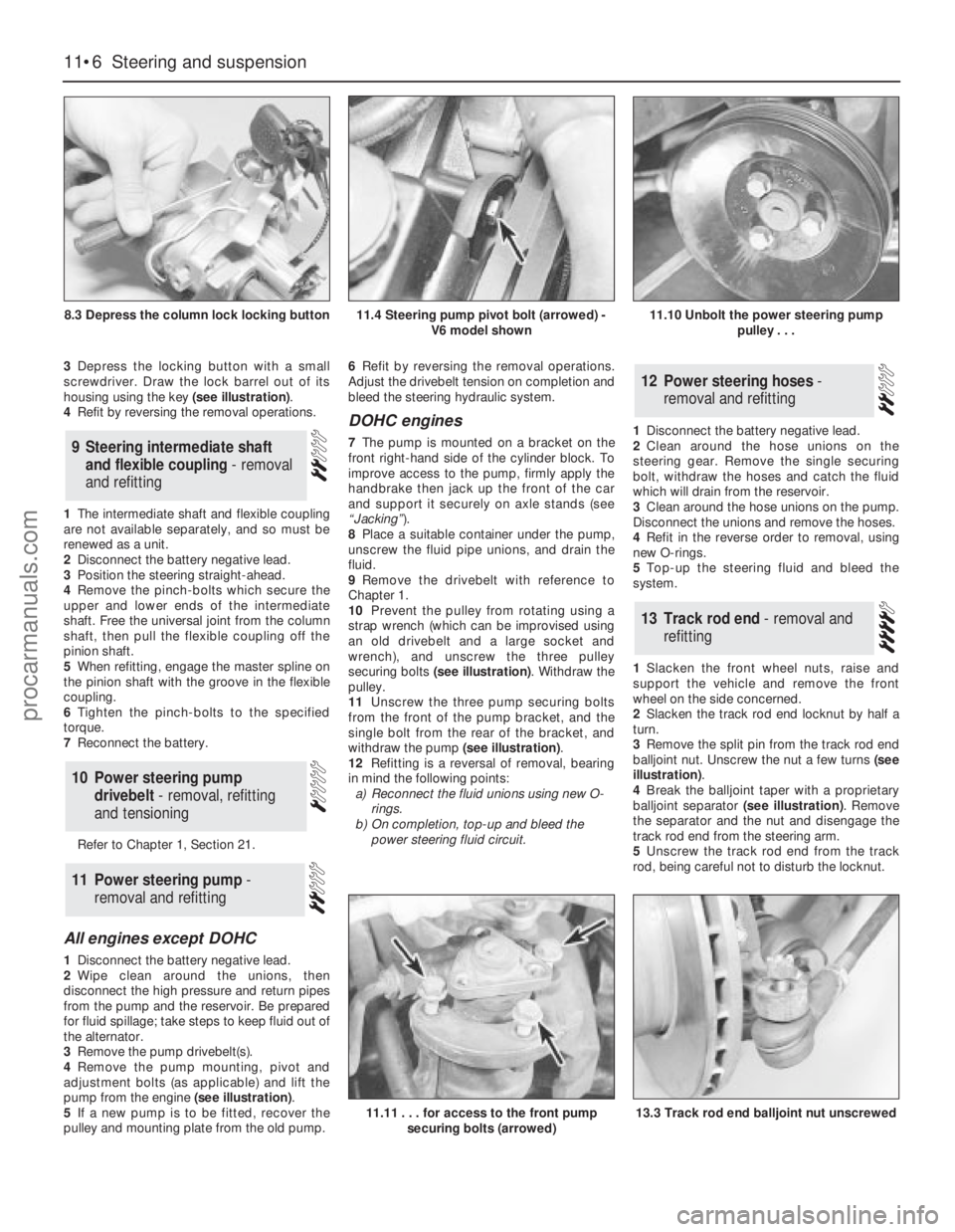
3Depress the locking button with a small
screwdriver. Draw the lock barrel out of its
housing using the key (see illustration).
4Refit by reversing the removal operations.
1The intermediate shaft and flexible coupling
are not available separately, and so must be
renewed as a unit.
2Disconnect the battery negative lead.
3Position the steering straight-ahead.
4Remove the pinch-bolts which secure the
upper and lower ends of the intermediate
shaft. Free the universal joint from the column
shaft, then pull the flexible coupling off the
pinion shaft.
5When refitting, engage the master spline on
the pinion shaft with the groove in the flexible
coupling.
6Tighten the pinch-bolts to the specified
torque.
7Reconnect the battery.
Refer to Chapter 1, Section 21.
All engines except DOHC
1Disconnect the battery negative lead.
2Wipe clean around the unions, then
disconnect the high pressure and return pipes
from the pump and the reservoir. Be prepared
for fluid spillage; take steps to keep fluid out of
the alternator.
3Remove the pump drivebelt(s).
4Remove the pump mounting, pivot and
adjustment bolts (as applicable) and lift the
pump from the engine (see illustration).
5If a new pump is to be fitted, recover the
pulley and mounting plate from the old pump.6Refit by reversing the removal operations.
Adjust the drivebelt tension on completion and
bleed the steering hydraulic system.
DOHC engines
7The pump is mounted on a bracket on the
front right-hand side of the cylinder block. To
improve access to the pump, firmly apply the
handbrake then jack up the front of the car
and support it securely on axle stands (see
“Jacking”).
8Place a suitable container under the pump,
unscrew the fluid pipe unions, and drain the
fluid.
9Remove the drivebelt with reference to
Chapter 1.
10Prevent the pulley from rotating using a
strap wrench (which can be improvised using
an old drivebelt and a large socket and
wrench), and unscrew the three pulley
securing bolts (see illustration). Withdraw the
pulley.
11Unscrew the three pump securing bolts
from the front of the pump bracket, and the
single bolt from the rear of the bracket, and
withdraw the pump (see illustration).
12Refitting is a reversal of removal, bearing
in mind the following points:
a)Reconnect the fluid unions using new O-
rings.
b)On completion, top-up and bleed the
power steering fluid circuit.1Disconnect the battery negative lead.
2Clean around the hose unions on the
steering gear. Remove the single securing
bolt, withdraw the hoses and catch the fluid
which will drain from the reservoir.
3Clean around the hose unions on the pump.
Disconnect the unions and remove the hoses.
4Refit in the reverse order to removal, using
new O-rings.
5Top-up the steering fluid and bleed the
system.
1Slacken the front wheel nuts, raise and
support the vehicle and remove the front
wheel on the side concerned.
2Slacken the track rod end locknut by half a
turn.
3Remove the split pin from the track rod end
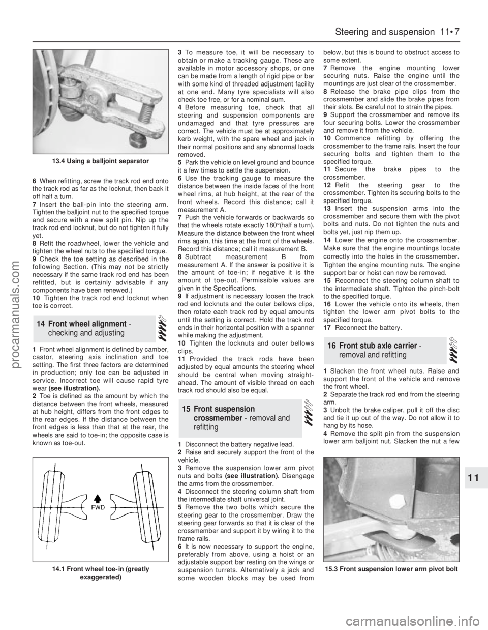
balljoint nut. Unscrew the nut a few turns (see
illustration).
4Break the balljoint taper with a proprietary
balljoint separator (see illustration). Remove
the separator and the nut and disengage the
track rod end from the steering arm.
5Unscrew the track rod end from the track
rod, being careful not to disturb the locknut.
13Track rod end - removal and
refitting
12Power steering hoses -
removal and refitting
11Power steering pump -
removal and refitting
10Power steering pump
drivebelt - removal, refitting
and tensioning
9Steering intermediate shaft
and flexible coupling - removal
and refitting
11•6Steering and suspension
8.3 Depress the column lock locking button
11.11 . . . for access to the front pump
securing bolts (arrowed)13.3 Track rod end balljoint nut unscrewed
11.4 Steering pump pivot bolt (arrowed) -
V6 model shown11.10 Unbolt the power steering pump
pulley . . .
procarmanuals.com
Page 150 of 255
6When refitting, screw the track rod end onto
the track rod as far as the locknut, then back it
off half a turn.
7Insert the ball-pin into the steering arm.
Tighten the balljoint nut to the specified torque
and secure with a new split pin. Nip up the
track rod end locknut, but do not tighten it fully
yet.
8Refit the roadwheel, lower the vehicle and
tighten the wheel nuts to the specified torque.
9Check the toe setting as described in the
following Section. (This may not be strictly
necessary if the same track rod end has been
refitted, but is certainly advisable if any
components have been renewed.)
10Tighten the track rod end locknut when
toe is correct.
1Front wheel alignment is defined by camber,
castor, steering axis inclination and toe
setting. The first three factors are determined
in production; only toe can be adjusted in
service. Incorrect toe will cause rapid tyre
wear (see illustration).
2Toe is defined as the amount by which the
distance between the front wheels, measured
at hub height, differs from the front edges to
the rear edges. If the distance between the
front edges is less than that at the rear, the
wheels are said to toe-in; the opposite case is
known as toe-out.3To measure toe, it will be necessary to
obtain or make a tracking gauge. These are
available in motor accessory shops, or one
can be made from a length of rigid pipe or bar
with some kind of threaded adjustment facility
at one end. Many tyre specialists will also
check toe free, or for a nominal sum.
4Before measuring toe, check that all
steering and suspension components are
undamaged and that tyre pressures are
correct. The vehicle must be at approximately
kerb weight, with the spare wheel and jack in
their normal positions and any abnormal loads
removed.
5Park the vehicle on level ground and bounce
it a few times to settle the suspension.
6Use the tracking gauge to measure the
distance between the inside faces of the front
wheel rims, at hub height, at the rear of the
front wheels. Record this distance; call it
measurement A.
7Push the vehicle forwards or backwards so
that the wheels rotate exactly 180°(half a turn).
Measure the distance between the front wheel
rims again, this time at the front of the wheels.
Record this distance; call it measurement B.
8Subtract measurement B from
measurement A. If the answer is positive it is
the amount of toe-in; if negative it is the
amount of toe-out. Permissible values are
given in the Specifications.
9If adjustment is necessary loosen the track
rod end locknuts and the outer bellows clips,
then rotate each track rod by equal amounts
until the setting is correct. Hold the track rod
ends in their horizontal position with a spanner
while making the adjustment.
10Tighten the locknuts and outer bellows
clips.
11Provided the track rods have been
adjusted by equal amounts the steering wheel
should be central when moving straight-
ahead. The amount of visible thread on each
track rod should also be equal.
1Disconnect the battery negative lead.
2Raise and securely support the front of the
vehicle.
3Remove the suspension lower arm pivot
nuts and bolts (see illustration). Disengage
the arms from the crossmember.
4Disconnect the steering column shaft from
the intermediate shaft universal joint.
5Remove the two bolts which secure the
steering gear to the crossmember. Draw the
steering gear forwards so that it is clear of the
crossmember and support it by wiring it to the
frame rails.
6It is now necessary to support the engine,
preferably from above, using a hoist or an
adjustable support bar resting on the wings or
suspension turrets. Alternatively a jack and
some wooden blocks may be used frombelow, but this is bound to obstruct access to
some extent.
7Remove the engine mounting lower
securing nuts. Raise the engine until the
mountings are just clear of the crossmember.
8Release the brake pipe clips from the
crossmember and slide the brake pipes from
their slots. Be careful not to strain the pipes.
9Support the crossmember and remove its
four securing bolts. Lower the crossmember
and remove it from the vehicle.
10Commence refitting by offering the
crossmember to the frame rails. Insert the four
securing bolts and tighten them to the
specified torque.
11Secure the brake pipes to the
crossmember.
12Refit the steering gear to the
crossmember. Tighten its securing bolts to the
specified torque.
13Insert the suspension arms into the
crossmember and secure them with the pivot
bolts and nuts. Do not tighten the nuts and
bolts yet, just nip them up.
14Lower the engine onto the crossmember.
Make sure that the engine mountings locate
correctly into the holes in the crossmember.
Tighten the engine mounting nuts. The engine
support bar or hoist can now be removed.
15Reconnect the steering column shaft to
the intermediate shaft. Tighten the pinch-bolt
to the specified torque.
16Lower the vehicle onto its wheels, then
tighten the lower arm pivot bolts to the
specified torque.
17Reconnect the battery.
1Slacken the front wheel nuts. Raise and
support the front of the vehicle and remove
the front wheel.
2Separate the track rod end from the steering
arm.
3Unbolt the brake caliper, pull it off the disc
and tie it up out of the way. Do not allow it to
hang by its hose.
4Remove the split pin from the suspension
lower arm balljoint nut. Slacken the nut a few
16Front stub axle carrier -
removal and refitting
15Front suspension
crossmember - removal and
refitting
14Front wheel alignment -
checking and adjusting
Steering and suspension 11•7
11
13.4 Using a balljoint separator
14.1 Front wheel toe-in (greatly
exaggerated)15.3 Front suspension lower arm pivot bolt
procarmanuals.com
Page 151 of 255
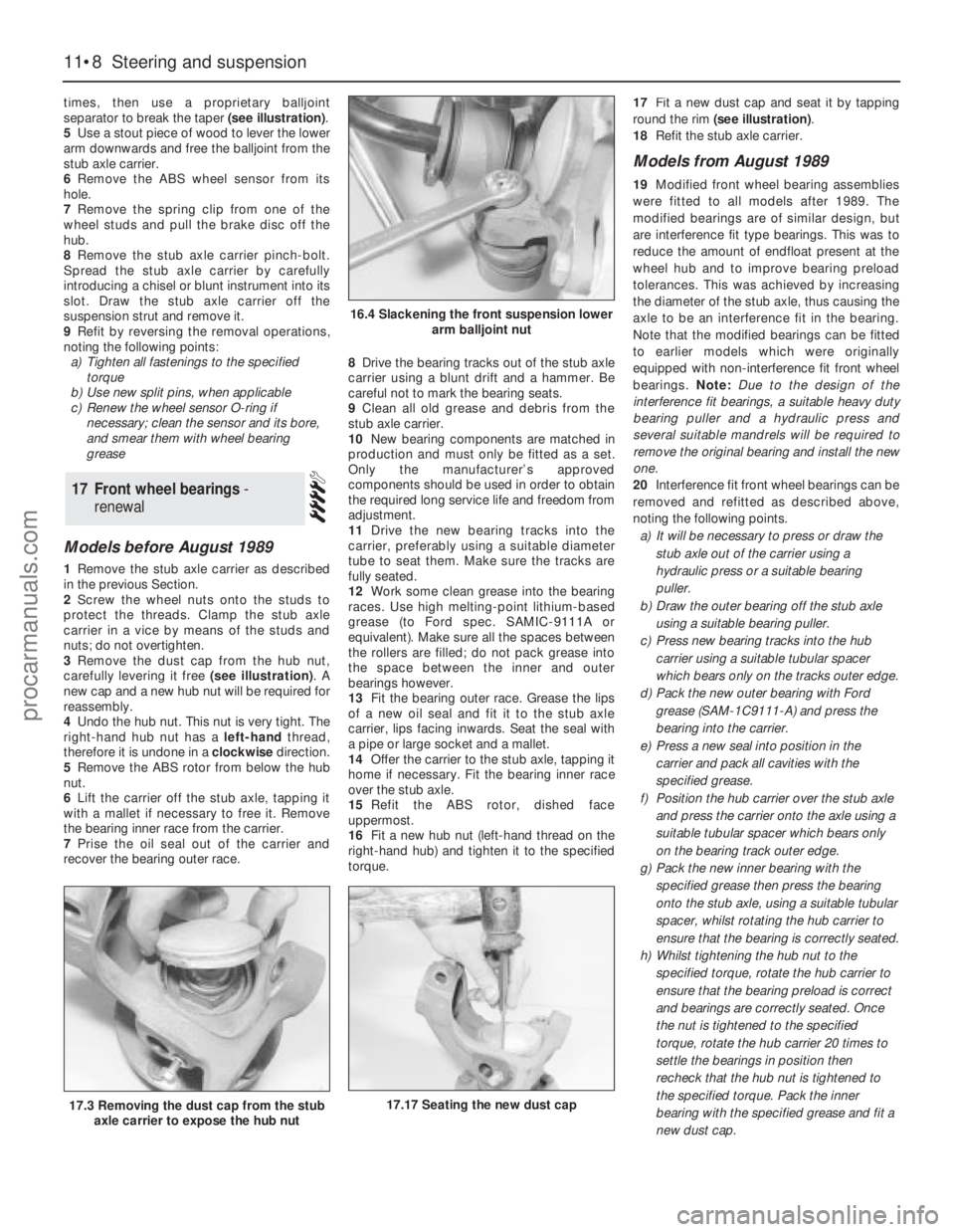
times, then use a proprietary balljoint
separator to break the taper (see illustration).
5Use a stout piece of wood to lever the lower
arm downwards and free the balljoint from the
stub axle carrier.
6Remove the ABS wheel sensor from its
hole.
7Remove the spring clip from one of the
wheel studs and pull the brake disc off the
hub.
8Remove the stub axle carrier pinch-bolt.
Spread the stub axle carrier by carefully
introducing a chisel or blunt instrument into its
slot. Draw the stub axle carrier off the
suspension strut and remove it.
9Refit by reversing the removal operations,
noting the following points:
a)Tighten all fastenings to the specified
torque
b)Use new split pins, when applicable
c)Renew the wheel sensor O-ring if
necessary; clean the sensor and its bore,
and smear them with wheel bearing
grease
Models before August 1989
1Remove the stub axle carrier as described
in the previous Section.
2Screw the wheel nuts onto the studs to
protect the threads. Clamp the stub axle
carrier in a vice by means of the studs and
nuts; do not overtighten.
3Remove the dust cap from the hub nut,
carefully levering it free (see illustration). A
new cap and a new hub nut will be required for
reassembly.
4Undo the hub nut. This nut is very tight. The
right-hand hub nut has a left-handthread,
therefore it is undone in a clockwisedirection.
5Remove the ABS rotor from below the hub
nut.
6Lift the carrier off the stub axle, tapping it
with a mallet if necessary to free it. Remove
the bearing inner race from the carrier.
7Prise the oil seal out of the carrier and
recover the bearing outer race.8Drive the bearing tracks out of the stub axle
carrier using a blunt drift and a hammer. Be
careful not to mark the bearing seats.
9Clean all old grease and debris from the
stub axle carrier.
10New bearing components are matched in
production and must only be fitted as a set.
Only the manufacturer’s approved
components should be used in order to obtain
the required long service life and freedom from
adjustment.
11Drive the new bearing tracks into the
carrier, preferably using a suitable diameter
tube to seat them. Make sure the tracks are
fully seated.
12Work some clean grease into the bearing
races. Use high melting-point lithium-based
grease (to Ford spec. SAMIC-9111A or
equivalent). Make sure all the spaces between
the rollers are filled; do not pack grease into
the space between the inner and outer
bearings however.
13Fit the bearing outer race. Grease the lips
of a new oil seal and fit it to the stub axle
carrier, lips facing inwards. Seat the seal with
a pipe or large socket and a mallet.
14Offer the carrier to the stub axle, tapping it
home if necessary. Fit the bearing inner race
over the stub axle.
15Refit the ABS rotor, dished face
uppermost.
16Fit a new hub nut (left-hand thread on the
right-hand hub) and tighten it to the specified
torque.17Fit a new dust cap and seat it by tapping
round the rim (see illustration).
18Refit the stub axle carrier.
Models from August 1989
19Modified front wheel bearing assemblies
were fitted to all models after 1989. The
modified bearings are of similar design, but
are interference fit type bearings. This was to
reduce the amount of endfloat present at the
wheel hub and to improve bearing preload
tolerances. This was achieved by increasing
the diameter of the stub axle, thus causing the
axle to be an interference fit in the bearing.
Note that the modified bearings can be fitted
to earlier models which were originally
equipped with non-interference fit front wheel
bearings. Note: Due to the design of the
interference fit bearings, a suitable heavy duty
bearing puller and a hydraulic press and
several suitable mandrels will be required to
remove the originalbearing and install the new
one.
20Interference fit front wheel bearings can be
removed and refitted as described above,
noting the following points.
a)It will be necessary to press or draw the
stub axle out of the carrier using a
hydraulic press or a suitable bearing
puller.
b)Draw the outer bearing off the stub axle
using a suitable bearing puller.
c)Press new bearing tracks into the hub
carrier using a suitable tubular spacer
which bears only on the tracks outer edge.
d)Pack the new outer bearing with Ford
grease (SAM-1C9111-A) and press the
bearing into the carrier.
e)Press a new seal into position in the
carrier and pack all cavities with the
specified grease.
f)Position the hub carrier over the stub axle
and press the carrier onto the axle using a
suitable tubular spacer which bears only
on the bearing track outer edge.
g)Pack the new inner bearing with the
specified grease then press the bearing
onto the stub axle, using a suitable tubular
spacer, whilst rotating the hub carrier to
ensure that the bearing is correctly seated.
h)Whilst tightening the hub nut to the
specified torque, rotate the hub carrier to
ensure that the bearing preload is correct
and bearings are correctly seated. Once
the nut is tightened to the specified
torque, rotate the hub carrier 20 times to
settle the bearings in position then
recheck that the hub nut is tightened to
the specified torque. Pack the inner
bearing with the specified grease and fit a
new dust cap.
17Front wheel bearings -
renewal
11•8Steering and suspension
16.4 Slackening the front suspension lower
arm balljoint nut
17.17 Seating the new dust cap17.3 Removing the dust cap from the stub
axle carrier to expose the hub nut
procarmanuals.com
Page 152 of 255
1Raise the vehicle on ramps or on a hoist, so
that the weight is still on the wheels.
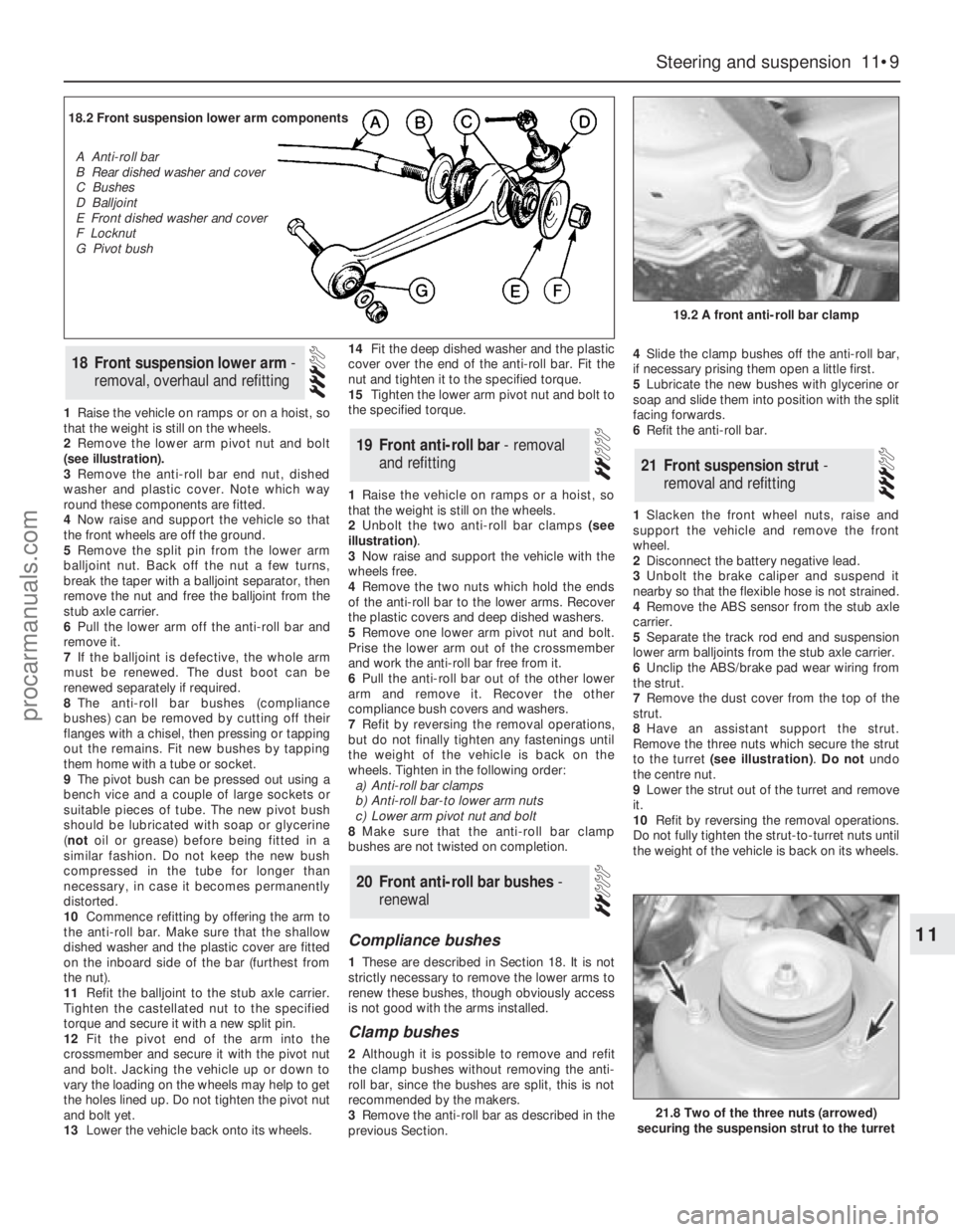
2Remove the lower arm pivot nut and bolt
(see illustration).
3Remove the anti-roll bar end nut, dished
washer and plastic cover. Note which way
round these components are fitted.
4Now raise and support the vehicle so that
the front wheels are off the ground.
5Remove the split pin from the lower arm
balljoint nut. Back off the nut a few turns,
break the taper with a balljoint separator, then
remove the nut and free the balljoint from the
stub axle carrier.
6Pull the lower arm off the anti-roll bar and
remove it.
7If the balljoint is defective, the whole arm
must be renewed. The dust boot can be
renewed separately if required.
8The anti-roll bar bushes (compliance
bushes) can be removed by cutting off their
flanges with a chisel, then pressing or tapping
out the remains. Fit new bushes by tapping
them home with a tube or socket.
9The pivot bush can be pressed out using a
bench vice and a couple of large sockets or
suitable pieces of tube. The new pivot bush
should be lubricated with soap or glycerine
(notoil or grease) before being fitted in a
similar fashion. Do not keep the new bush
compressed in the tube for longer than
necessary, in case it becomes permanently
distorted.
10Commence refitting by offering the arm to
the anti-roll bar. Make sure that the shallow
dished washer and the plastic cover are fitted
on the inboard side of the bar (furthest from
the nut).
11Refit the balljoint to the stub axle carrier.
Tighten the castellated nut to the specified
torque and secure it with a new split pin.
12Fit the pivot end of the arm into the
crossmember and secure it with the pivot nut
and bolt. Jacking the vehicle up or down to
vary the loading on the wheels may help to get
the holes lined up. Do not tighten the pivot nut
and bolt yet.
13Lower the vehicle back onto its wheels.14Fit the deep dished washer and the plastic
cover over the end of the anti-roll bar. Fit the
nut and tighten it to the specified torque.
15Tighten the lower arm pivot nut and bolt to
the specified torque.
1Raise the vehicle on ramps or a hoist, so
that the weight is still on the wheels.
2Unbolt the two anti-roll bar clamps (see
illustration).
3Now raise and support the vehicle with the
wheels free.
4Remove the two nuts which hold the ends
of the anti-roll bar to the lower arms. Recover
the plastic covers and deep dished washers.
5Remove one lower arm pivot nut and bolt.
Prise the lower arm out of the crossmember
and work the anti-roll bar free from it.
6Pull the anti-roll bar out of the other lower
arm and remove it. Recover the other
compliance bush covers and washers.
7Refit by reversing the removal operations,
but do not finally tighten any fastenings until
the weight of the vehicle is back on the
wheels. Tighten in the following order:
a)Anti-roll bar clamps
b)Anti-roll bar-to lower arm nuts
c)Lower arm pivot nut and bolt
8Make sure that the anti-roll bar clamp
bushes are not twisted on completion.
Compliance bushes
1These are described in Section 18. It is not
strictly necessary to remove the lower arms to
renew these bushes, though obviously access
is not good with the arms installed.
Clamp bushes
2Although it is possible to remove and refit
the clamp bushes without removing the anti-
roll bar, since the bushes are split, this is not
recommended by the makers.
3Remove the anti-roll bar as described in the
previous Section.4Slide the clamp bushes off the anti-roll bar,
if necessary prising them open a little first.
5Lubricate the new bushes with glycerine or
soap and slide them into position with the split
facing forwards.
6Refit the anti-roll bar.
1Slacken the front wheel nuts, raise and
support the vehicle and remove the front
wheel.
2Disconnect the battery negative lead.
3Unbolt the brake caliper and suspend it
nearby so that the flexible hose is not strained.
4Remove the ABS sensor from the stub axle
carrier.
5Separate the track rod end and suspension
lower arm balljoints from the stub axle carrier.
6Unclip the ABS/brake pad wear wiring from
the strut.
7Remove the dust cover from the top of the
strut.
8Have an assistant support the strut.
Remove the three nuts which secure the strut
to the turret (see illustration).Do notundo
the centre nut.
9Lower the strut out of the turret and remove
it.
10Refit by reversing the removal operations.
Do not fully tighten the strut-to-turret nuts until
the weight of the vehicle is back on its wheels.
21Front suspension strut -
removal and refitting
20Front anti-roll bar bushes -
renewal
19Front anti-roll bar - removal
and refitting
18Front suspension lower arm -
removal, overhaul and refitting
Steering and suspension 11•9
11
19.2 A front anti-roll bar clamp
21.8 Two of the three nuts (arrowed)
securing the suspension strut to the turret
18.2 Front suspension lower arm components
A Anti-roll bar
B Rear dished washer and cover
C Bushes
D Balljoint
E Front dished washer and cover
F Locknut
G Pivot bush
procarmanuals.com
Page 153 of 255
1With the strut removed, clamp it in a vice
with protected jaws.2Remove the stub axle carrier pinch-bolts.
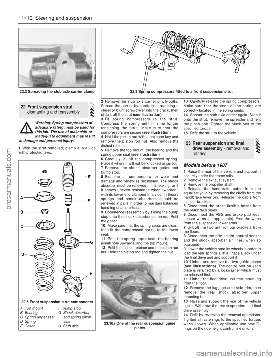
Spread the carrier by carefully introducing a
chisel or blunt screwdriver into the crack, then
slide it off the strut (see illustration).
3Fit spring compressors to the strut.
Compress the spring until it is no longer
tensioning the strut. Make sure that the
compressors are secure (see illustration).
4Hold the piston rod with a hexagon key and
remove the piston rod nut. Also remove the
dished retainer.
5Remove the top mount, the bearing and the
spring upper seat(see illustration).
6Carefully lift off the compressed spring.
Place it where it will not be knocked or jarred.
7Remove the shock absorber gaiter and
bump stop.
8Examine all components for wear and
damage and renew as necessary. The shock
absorber must be renewed if it is leaking, or if
it shows uneven resistance when “worked”
with its lower end clamped in a vice. In theory
springs and shock absorbers should be
renewed in pairs in order to maintain balanced
handling characteristics.
9Commence reassembly by sliding the bump
stop onto the shock absorber piston rod. Refit
the gaiter.
10Make sure that the spring seats are clean,
then fit the compressed spring to the lower
seat.
11Refit the spring upper seat, the bearing
(small hole upwards) and the top mount.
12Refit the dished retainer and the piston rod
nut. Hold the piston rod and tighten the nut.13Carefully release the spring compressors.
Make sure that the ends of the spring are
correctly located in the spring seats.
14Spread the stub axle carrier again. Slide it
onto the strut, remove the spreader and refit
the pinch-bolt. Tighten the pinch-bolt to the
specified torque.
15Refit the strut to the vehicle.
Models before 1987
1Raise the rear of the vehicle and support it
securely under the frame rails.
2Remove the exhaust system.
3Remove the propeller shaft.
4Release the handbrake cable from the
equaliser yoke by removing the circlip from the
handbrake lever pin. Release the cable from
its floor brackets.
5Disconnect the brake flexible hoses from
the rear brake pipes.
6Disconnect the ABS and brake pad wear
sensor wires (as applicable). Free the wires
from the suspension lower arms.
7Unbolt the two anti-roll bar brackets from
the floors.
8Disconnect the ride height control sensor
and the shock absorber air lines, when so
equipped.
9Lower the vehicle onto its wheels in order to
load the rear springs a little. Place a jack under
the final drive unit and support it.
10Unbolt and remove the two guide plates
(see illustrations). The centre bolt on each
plate is retained by a lockwasher which must
be released first.
11Unbolt the final drive unit rear mounting
from the floor.
12Remove the luggage area side trim, then
remove the rear shock absorber upper
mounting bolts.
13Raise and support the rear of the vehicle
again. Withdraw the rear suspension and final
drive assembly.
14Refit by reversing the removal operations.
Tighten all fastenings to the specified torque,
when known. When applicable use new O-
rings on the ride height control line unions.
23Rear suspension and final
drive assembly - removal and
refitting
22Front suspension strut -
dismantling and reassembly
11•10Steering and suspension
22.2 Spreading the stub axle carrier clamp22.3 Spring compressors fitted to a front suspension strut
22.5 Front suspension strut components
A Top mount
B Bearing
C Spring upper seat
D Spring
E GaiterF Bump stop
G Shock absorber
and spring lower
seat
H Stub axle
Warning: Spring compressors of
adequate rating must be used for
this job. The use of makeshift or
inadequate equipment may result
in damage and personal injury.
23.10a One of the rear suspension guide
plates
procarmanuals.com
Page 154 of 255
15Bleed the brake hydraulic system and
adjust the handbrake on completion.
Models from 1987
16From 1987, the tab washer which secures
the guide plate centre bolt on each side has
been deleted. A self-locking bolt and plain
washer are used instead.
17The new bolt and washer should be fitted
to earlier models if the old bolt has been
removed for any reason. The tab washer
should be discarded.
18The tightening torque for the new bolt
remains the same as that given for the original.
1Remove the wheel trim. Apply the
handbrake and chock the front wheels.
2Slacken the driveshaft stub axle. This nut is
very tight. The left-hand nut has aleft-hand
thread, therefore it is undone clockwise.
3Remove the brake disc.
4Remove the driveshaft stub axle.
5Remove the four bolts which secure the
hub. Pull the hub off the driveshaft stub,
leaving the disc splash shield loose.
6Refit by reversing the removal operations.
Carry out the final tightening of the driveshaft
stub nut with the wheels on the ground.
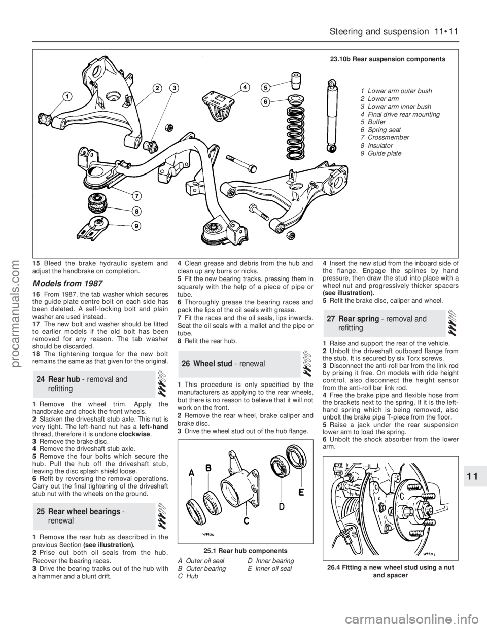
1Remove the rear hub as described in the
previous Section (see illustration).
2Prise out both oil seals from the hub.
Recover the bearing races.
3Drive the bearing tracks out of the hub with
a hammer and a blunt drift.4Clean grease and debris from the hub and
clean up any burrs or nicks.
5Fit the new bearing tracks, pressing them in
squarely with the help of a piece of pipe or
tube.
6Thoroughly grease the bearing races and
pack the lips of the oil seals with grease.
7Fit the races and the oil seals, lips inwards.
Seat the oil seals with a mallet and the pipe or
tube.
8Refit the rear hub.
1This procedure is only specified by the
manufacturers as applying to the rear wheels,
but there is no reason to believe that it will not
work on the front.
2Remove the rear wheel, brake caliper and
brake disc.
3Drive the wheel stud out of the hub flange. 4Insert the new stud from the inboard side of
the flange. Engage the splines by hand
pressure, then draw the stud into place with a
wheel nut and progressively thicker spacers
(see illustration).
5Refit the brake disc, caliper and wheel.
1Raise and support the rear of the vehicle.
2Unbolt the driveshaft outboard flange from
the stub. It is secured by six Torx screws.
3Disconnect the anti-roll bar from the link rod
by prising it free. On models with ride height
control, also disconnect the height sensor
from the anti-roll bar link rod.
4Free the brake pipe and flexible hose from
the brackets next to the spring. If it is the left-
hand spring which is being removed, also
unbolt the brake pipe T-piece from the floor.
5Raise a jack under the rear suspension
lower arm to load the spring.
6Unbolt the shock absorber from the lower
arm.
27Rear spring - removal and
refitting
26Wheel stud - renewal
25Rear wheel bearings -
renewal
24Rear hub - removal and
refitting
Steering and suspension 11•11
11
25.1 Rear hub components
A Outer oil seal
B Outer bearing
C HubD Inner bearing
E Inner oil seal26.4 Fitting a new wheel stud using a nut
and spacer
23.10b Rear suspension components
1 Lower arm outer bush
2 Lower arm
3 Lower arm inner bush
4 Final drive rear mounting
5 Buffer
6 Spring seat
7 Crossmember
8 Insulator
9 Guide plate
procarmanuals.com
Page 155 of 255
7Unbolt the guide plate from the body on the
side concerned.
8Carefully lower the jack until the spring is no
longer under tension. Remove the spring and
the rubber buffer.
9Refit by reversing the removal operations,
tightening all fastenings to the specified torque
when known.
Note: Ford tool No 15-014, or locally made
equivalent, will be required for this job.
1Raise and support the rear of the vehicle.
2Flatten the lockwasher which secures the
guide plate centre bolt. Remove the centre
bolt and the two bolts which hold the guide
plate to the floor; remove the guide plate.
3Wedge a piece of wood between the
crossmember and the floor.
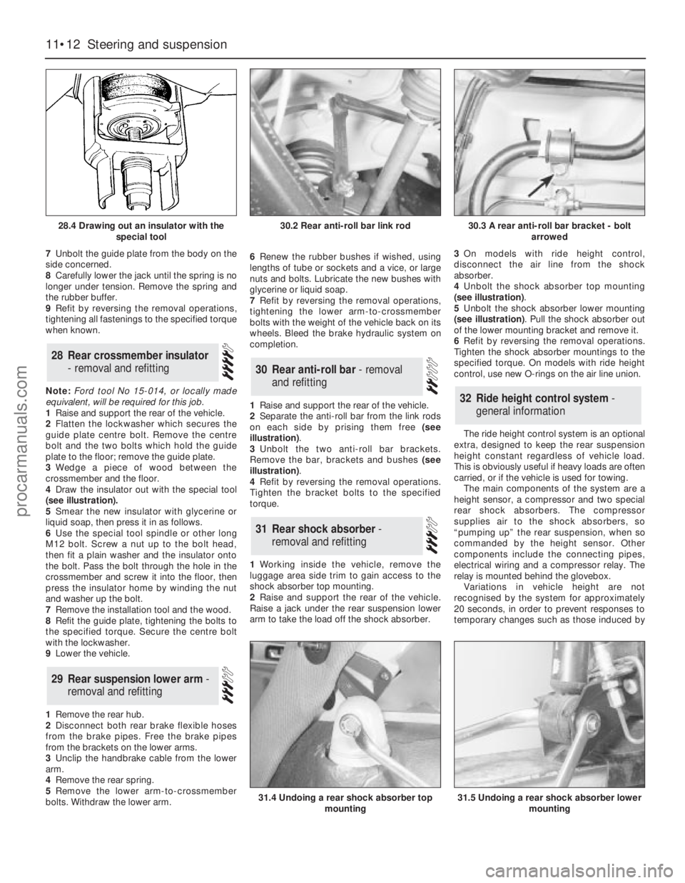
4Draw the insulator out with the special tool
(see illustration).
5Smear the new insulator with glycerine or
liquid soap, then press it in as follows.
6Use the special tool spindle or other long
M12 bolt. Screw a nut up to the bolt head,
then fit a plain washer and the insulator onto
the bolt. Pass the bolt through the hole in the
crossmember and screw it into the floor, then
press the insulator home by winding the nut
and washer up the bolt.
7Remove the installation tool and the wood.
8Refit the guide plate, tightening the bolts to
the specified torque. Secure the centre bolt
with the lockwasher.
9Lower the vehicle.
1Remove the rear hub.
2Disconnect both rear brake flexible hoses
from the brake pipes. Free the brake pipes
from the brackets on the lower arms.
3Unclip the handbrake cable from the lower
arm.
4Remove the rear spring.
5Remove the lower arm-to-crossmember
bolts. Withdraw the lower arm.6Renew the rubber bushes if wished, using
lengths of tube or sockets and a vice, or large
nuts and bolts. Lubricate the new bushes with
glycerine or liquid soap.
7Refit by reversing the removal operations,
tightening the lower arm-to-crossmember
bolts with the weight of the vehicle back on its
wheels. Bleed the brake hydraulic system on
completion.
1Raise and support the rear of the vehicle.
2Separate the anti-roll bar from the link rods
on each side by prising them free (see
illustration).
3Unbolt the two anti-roll bar brackets.
Remove the bar, brackets and bushes (see
illustration).
4Refit by reversing the removal operations.
Tighten the bracket bolts to the specified
torque.
1Working inside the vehicle, remove the
luggage area side trim to gain access to the
shock absorber top mounting.
2Raise and support the rear of the vehicle.
Raise a jack under the rear suspension lower
arm to take the load off the shock absorber.3On models with ride height control,
disconnect the air line from the shock
absorber.
4Unbolt the shock absorber top mounting
(see illustration).
5Unbolt the shock absorber lower mounting
(see illustration). Pull the shock absorber out
of the lower mounting bracket and remove it.
6Refit by reversing the removal operations.
Tighten the shock absorber mountings to the
specified torque. On models with ride height
control, use new O-rings on the air line union.
The ride height control system is an optional
extra, designed to keep the rear suspension
height constant regardless of vehicle load.
This is obviously useful if heavy loads are often
carried, or if the vehicle is used for towing.
The main components of the system are a
height sensor, a compressor and two special
rear shock absorbers. The compressor
supplies air to the shock absorbers, so
“pumping up” the rear suspension, when so
commanded by the height sensor. Other
components include the connecting pipes,
electrical wiring and a compressor relay. The
relay is mounted behind the glovebox.
Variations in vehicle height are not
recognised by the system for approximately
20 seconds, in order to prevent responses to
temporary changes such as those induced by
32Ride height control system -
general information
31Rear shock absorber -
removal and refitting
30Rear anti-roll bar - removal
and refitting
29Rear suspension lower arm -
removal and refitting
28Rear crossmember insulator
- removal and refitting
11•12Steering and suspension
28.4 Drawing out an insulator with the
special tool
31.4 Undoing a rear shock absorber top
mounting31.5 Undoing a rear shock absorber lower
mounting
30.2 Rear anti-roll bar link rod30.3 A rear anti-roll bar bracket - bolt
arrowed
procarmanuals.com
Page 158 of 255
Chapter 12
Bodywork and fittings
Bonnet - removal and refitting . . . . . . . . . . . . . . . . . . . . . . . . . . . . . .6
Bonnet insulation panel - removal and refitting . . . . . . . . . . . . . . . .26
Bonnet release cable - removal and refitting . . . . . . . . . . . . . . . . . .11
Boot lid lock barrel - removal and refitting . . . . . . . . . . . . . . . . . . . .18
Boot lid - removal, refitting and adjustment . . . . . . . . . . . . . . . . . . . .9
Bumper mouldings - removal and refitting . . . . . . . . . . . . . . . . . . . .36
Bumpers - removal and refitting . . . . . . . . . . . . . . . . . . . . . . . . . . . .35
Centre console - removal and refitting . . . . . . . . . . . . . . . . . . . . . . .42
Door - removal and refitting . . . . . . . . . . . . . . . . . . . . . . . . . . . . . . . .7
Door exterior handle - removal and refitting . . . . . . . . . . . . . . . . . .13
Door interior trim panel - removal and refitting . . . . . . . . . . . . . . . .22
Door latch assembly - removal and refitting . . . . . . . . . . . . . . . . . .15
Door lock barrel - removal and refitting . . . . . . . . . . . . . . . . . . . . . .14
Door striker plate - adjustment . . . . . . . . . . . . . . . . . . . . . . . . . . . . .12
Door weatherstrip - removal and refitting . . . . . . . . . . . . . . . . . . . .16
Door window frame mouldings - removal and refitting . . . . . . . . . .31
Door window glass - removal and refitting . . . . . . . . . . . . . . . . . . . .23
Door window regulator mechanism - removal and refitting . . . . . . .24
Exterior mirror - removal and refitting . . . . . . . . . . . . . . . . . . . . . . .39
Facia panels and trim - removal and refitting . . . . . . . . . . . . . . . . . .41
Front bumper - height adjustment . . . . . . . . . . . . . . . . . . . . . . . . . .34
Front seat - removal and refitting . . . . . . . . . . . . . . . . . . . . . . . . . . .44
Front seat air cushion - removal and refitting . . . . . . . . . . . . . . . . .45
Front seat belts - removal and refitting . . . . . . . . . . . . . . . . . . . . . .47
Front spoiler - removal and refitting . . . . . . . . . . . . . . . . . . . . . . . . .37Fuel filler lock barrel - removal and refitting . . . . . . . . . . . . . . . . . . .21
General information . . . . . . . . . . . . . . . . . . . . . . . . . . . . . . . . . . . . . .1
Headlining - removal and refitting . . . . . . . . . . . . . . . . . . . . . . . . . .38
Interior mirror - removal and refitting . . . . . . . . . . . . . . . . . . . . . . . .40
Maintenance - bodywork and underframe . . . . . . . . . . . . . . . . . . . . .2
Maintenance - upholstery and carpets . . . . . . . . . . . . . . . . . . . . . . . .3
Major body damage - repair . . . . . . . . . . . . . . . . . . . . . . . . . . . . . . . .5
Minor body damage - repair . . . . . . . . . . . . . . . . . . . . . . . . . . . . . . . .4
Motifs and emblems - removal and refitting . . . . . . . . . . . . . . . . . .33
Overhead console - removal and refitting . . . . . . . . . . . . . . . . . . . .43
Radiator grille - removal and refitting . . . . . . . . . . . . . . . . . . . . . . . .27
Rear parcel shelf - removal and refitting . . . . . . . . . . . . . . . . . . . . .50
Rear quarter window moulding - removal and refitting . . . . . . . . . .32
Rear seat belts - removal and refitting . . . . . . . . . . . . . . . . . . . . . . .48
Rear seat components - removal and refitting . . . . . . . . . . . . . . . . .49
Seat belts - care and maintenance . . . . . . . . . . . . . . . . . . . . . . . . .46
Side mouldings - removal and refitting . . . . . . . . . . . . . . . . . . . . . .28
Sliding roof - removal and refitting . . . . . . . . . . . . . . . . . . . . . . . . . .10
Tailgate - removal and refitting . . . . . . . . . . . . . . . . . . . . . . . . . . . . . .8
Tailgate latch assembly - removal and refitting . . . . . . . . . . . . . . . .19
Tailgate lock barrel - removal and refitting . . . . . . . . . . . . . . . . . . . .17
Tailgate strut - removal and refitting . . . . . . . . . . . . . . . . . . . . . . . .20
Tailgate window mouldings - removal and refitting . . . . . . . . . . . . .30
Windscreen and fixed glass - removal and refitting . . . . . . . . . . . . .25
Windscreen mouldings - removal and refitting . . . . . . . . . . . . . . . .29
Torque wrench settingsNm lbf ft
Front seat belt buckle to seat frame . . . . . . . . . . . . . . . . . . . . . . . . . . . . 51 to 64 38 to 47
Seat belt retractor bolts (front and rear) . . . . . . . . . . . . . . . . . . . . . . . . . 25 to 45 18 to 33
Other seat belt anchorages . . . . . . . . . . . . . . . . . . . . . . . . . . . . . . . . . . 25 to 45 18 to 33
Rear seat back hinge to body . . . . . . . . . . . . . . . . . . . . . . . . . . . . . . . . . 21 to 25 16 to 18
Rear seat back latch striker . . . . . . . . . . . . . . . . . . . . . . . . . . . . . . . . . . 40 to 60 30 to 44
Front seat retaining bolts . . . . . . . . . . . . . . . . . . . . . . . . . . . . . . . . . . . . 25 to 32 18 to 24
Front seat frame-to-slide bolts . . . . . . . . . . . . . . . . . . . . . . . . . . . . . . . . 25 to 32 18 to 24
Rear bumper mountings . . . . . . . . . . . . . . . . . . . . . . . . . . . . . . . . . . . . . 21 16
Front bumper adjuster lockbolt . . . . . . . . . . . . . . . . . . . . . . . . . . . . . . . 21 16
12•1
Easy,suitable for
novice with little
experienceFairly easy,suitable
for beginner with
some experienceFairly difficult,
suitable for competent
DIY mechanicDifficult,suitable for
experienced DIY
mechanicVery difficult,
suitable for expert
DIY or professional
Degrees of difficulty
Specifications Contents
12
The bodyshell and floorpan are of pressed
steel, and form an integral part of the vehicle’s
structure. Various reinforcing and mounting
components beneath the floorpan are made of
HSLA (High Strength Low Alloy) and REPHOS
(rephosphorised) steels, which have superiorstrength-to-weight characteristics when
compared with conventional steels.
Extensive use is made of plastic for
peripheral components such as the radiator
grille, bumpers and wheel trims, and for much
of the interior trim.
Interior fittings are to the high standard
expected in a vehicle of this class, with even
the basic level models well equipped. A wide
range of options is available, including air
conditioning and leather upholstery.The general condition of a vehicle’s
bodywork is the one thing that significantly
affects its value. Maintenance is easy, but
needs to be regular. Neglect, particularly after
minor damage, can lead quickly to further
deterioration and costly repair bills. It is
2 Maintenance - bodywork and
underframe1 General information
procarmanuals.com