1985 FORD GRANADA fuel filter
[x] Cancel search: fuel filterPage 98 of 255
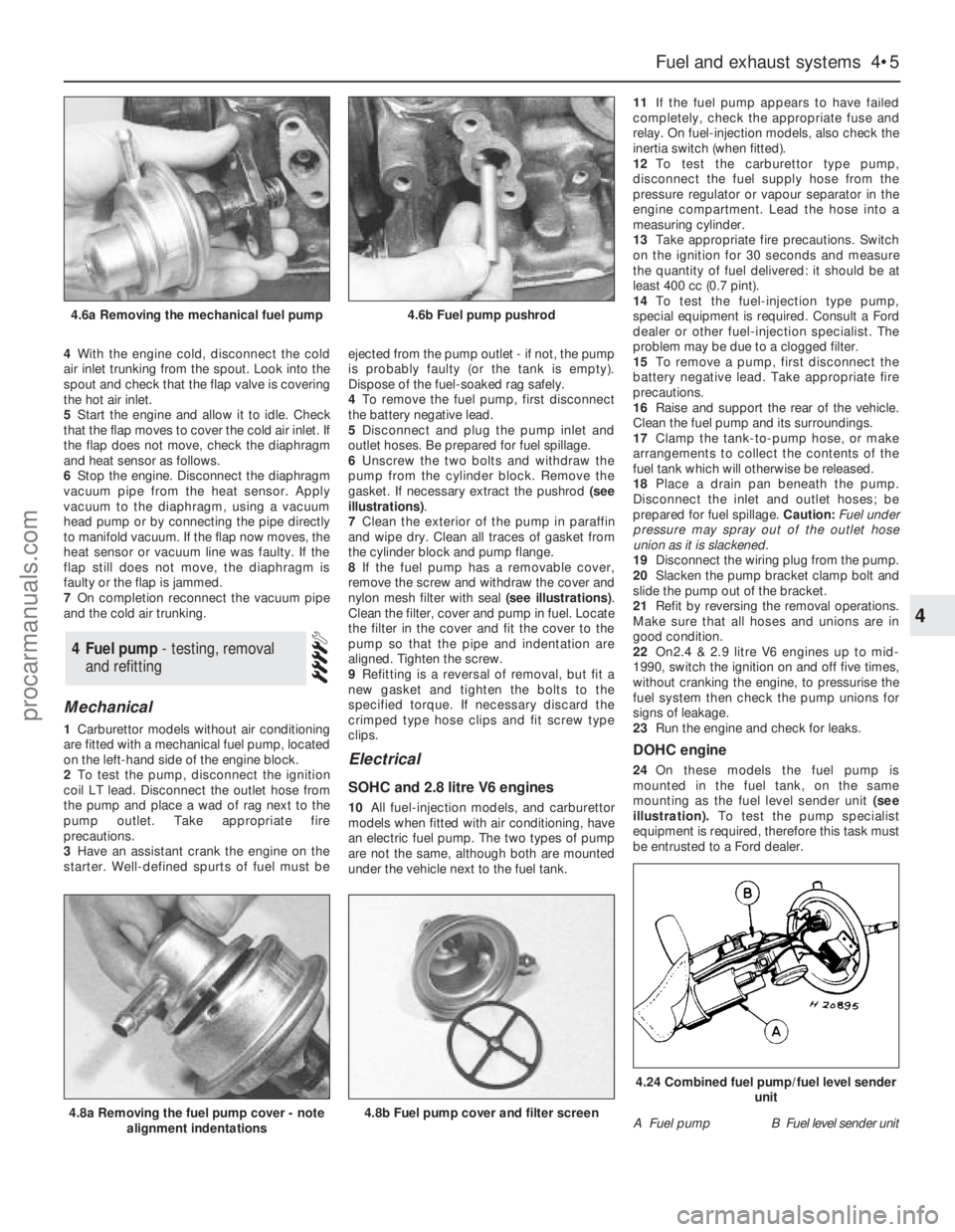
4With the engine cold, disconnect the cold
air inlet trunking from the spout. Look into the
spout and check that the flap valve is covering
the hot air inlet.
5Start the engine and allow it to idle. Check
that the flap moves to cover the cold air inlet. If
the flap does not move, check the diaphragm
and heat sensor as follows.
6Stop the engine. Disconnect the diaphragm
vacuum pipe from the heat sensor. Apply
vacuum to the diaphragm, using a vacuum
head pump or by connecting the pipe directly
to manifold vacuum. If the flap now moves, the
heat sensor or vacuum line was faulty. If the
flap still does not move, the diaphragm is
faulty or the flap is jammed.
7On completion reconnect the vacuum pipe
and the cold air trunking.
Mechanical
1Carburettor models without air conditioning
are fitted with a mechanical fuel pump, located
on the left-hand side of the engine block.
2To test the pump, disconnect the ignition
coil LT lead. Disconnect the outlet hose from
the pump and place a wad of rag next to the
pump outlet. Take appropriate fire
precautions.
3Have an assistant crank the engine on the
starter. Well-defined spurts of fuel must beejected from the pump outlet - if not, the pump
is probably faulty (or the tank is empty).
Dispose of the fuel-soaked rag safely.
4To remove the fuel pump, first disconnect
the battery negative lead.
5Disconnect and plug the pump inlet and
outlet hoses. Be prepared for fuel spillage.
6Unscrew the two bolts and withdraw the
pump from the cylinder block. Remove the
gasket. If necessary extract the pushrod (see
illustrations).
7Clean the exterior of the pump in paraffin
and wipe dry. Clean all traces of gasket from
the cylinder block and pump flange.
8If the fuel pump has a removable cover,
remove the screw and withdraw the cover and
nylon mesh filter with seal (see illustrations).
Clean the filter, cover and pump in fuel. Locate
the filter in the cover and fit the cover to the
pump so that the pipe and indentation are
aligned. Tighten the screw.
9Refitting is a reversal of removal, but fit a
new gasket and tighten the bolts to the
specified torque. If necessary discard the
crimped type hose clips and fit screw type
clips.
Electrical
SOHC and 2.8 litre V6 engines
10All fuel-injection models, and carburettor
models when fitted with air conditioning, have
an electric fuel pump. The two types of pump
are not the same, although both are mounted
under the vehicle next to the fuel tank.11If the fuel pump appears to have failed
completely, check the appropriate fuse and
relay. On fuel-injection models, also check the
inertia switch (when fitted).
12To test the carburettor type pump,
disconnect the fuel supply hose from the
pressure regulator or vapour separator in the
engine compartment. Lead the hose into a
measuring cylinder.
13Take appropriate fire precautions. Switch
on the ignition for 30 seconds and measure
the quantity of fuel delivered: it should be at
least 400 cc (0.7 pint).
14To test the fuel-injection type pump,
special equipment is required. Consult a Ford
dealer or other fuel-injection specialist. The
problem may be due to a clogged filter.
15To remove a pump, first disconnect the
battery negative lead. Take appropriate fire
precautions.
16Raise and support the rear of the vehicle.
Clean the fuel pump and its surroundings.
17Clamp the tank-to-pump hose, or make
arrangements to collect the contents of the
fuel tank which will otherwise be released.
18Place a drain pan beneath the pump.
Disconnect the inlet and outlet hoses; be
prepared for fuel spillage. Caution: Fuel under
pressure may spray out of the outlet hose
union as it is slackened.
19Disconnect the wiring plug from the pump.
20Slacken the pump bracket clamp bolt and
slide the pump out of the bracket.
21Refit by reversing the removal operations.
Make sure that all hoses and unions are in
good condition.
22On2.4 & 2.9 litre V6 engines up to mid-
1990, switch the ignition on and off five times,
without cranking the engine, to pressurise the
fuel system then check the pump unions for
signs of leakage.
23Run the engine and check for leaks.
DOHC engine
24On these models the fuel pump is
mounted in the fuel tank, on the same
mounting as the fuel level sender unit(see
illustration).To test the pump specialist
equipment is required, therefore this task must
be entrusted to a Ford dealer.
4Fuel pump - testing, removal
and refitting
Fuel and exhaust systems 4•5
4
4.6a Removing the mechanical fuel pump4.6b Fuel pump pushrod
4.8a Removing the fuel pump cover - note
alignment indentations4.8b Fuel pump cover and filter screenA Fuel pumpB Fuel level sender unit
4.24 Combined fuel pump/fuel level sender
unit
procarmanuals.com
Page 101 of 255
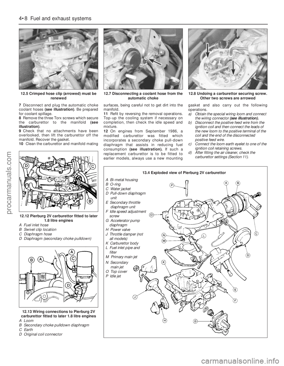
7Disconnect and plug the automatic choke
coolant hoses (see illustration). Be prepared
for coolant spillage.
8Remove the three Torx screws which secure
the carburettor to the manifold (see
illustration).
9Check that no attachments have been
overlooked, then lift the carburettor off the
manifold. Recover the gasket.
10Clean the carburettor and manifold matingsurfaces, being careful not to get dirt into the
manifold.
11Refit by reversing the removal operations.
Top-up the cooling system if necessary on
completion, then check the idle speed and
mixture.
12On engines from September 1986, a
modified carburettor was fitted which
incorporates a secondary choke pull-down
diaphragm that assists in reducing fuel
consumption (see illustration).If such a
replacement carburettor is to be fitted to
earlier models, always use a new mountinggasket and also carry out the following
operations.
a)Obtain the special wiring loom and connect
the wiring connector(see illustration).
b)Disconnect the positive feed wire from the
ignition coil and then connect the leads of
the new loom to the positive terminal of the
coil and the end of the disconnected
positive feed wire.
c)Connect the loom earth eyelet to one of the
ignition coil retaining screws.
d)After fitting the air cleaner, check the
carburettor settings (Section 11).
4•8Fuel and exhaust systems
12.5 Crimped hose clip (arrowed) must be
renewed
12.12 Pierburg 2V carburettor fitted to later
1.8 litre engines
A Fuel inlet hose
B Swivel clip location
C Diaphragm hose
D Diaphragm (secondary choke pulldown)
12.13 Wiring connections to Pierburg 2V
carburettor fitted to later 1.8 litre engines
A Loom
B Secondary choke pulldown diaphragm
C Earth
D Original coil connector
12.7 Disconnecting a coolant hose from the
automatic choke12.8 Undoing a carburettor securing screw.
Other two screws are arrowed
13.4 Exploded view of Pierburg 2V carburettor
A Bi-metal housing
B O-ring
C Water jacket
D Pull-down diaphragm
unit
E Secondary throttle
diaphragm unit
F Idle speed adjustment
screw
G Accelerator pump
diaphragm
H Power valve
J Throttle damper (not
all models)
K Carburettor body
L Fuel inlet pipe and
filter
M Primary main jet
N Secondary
main jet
O Top cover
P Idle jet
procarmanuals.com
Page 103 of 255
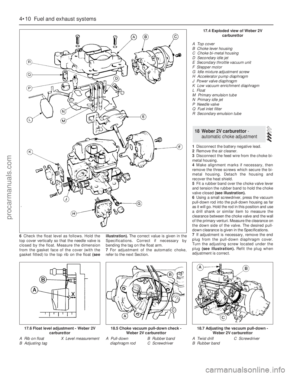
6Check the float level as follows. Hold the
top cover vertically so that the needle valve is
closed by the float. Measure the dimension
from the gasket face of the cover (with the
gasket fitted) to the top rib on the float(seeillustration).The correct value is given in the
Specifications. Correct if necessary by
bending the tag on the float arm.
7For adjustment of the automatic choke,
refer to the next Section.1Disconnect the battery negative lead.
2Remove the air cleaner.
3Disconnect the feed wire from the choke bi-
metal housing.
4Make alignment marks if necessary, then
remove the three screws which secure the bi-
metal housing. Detach thehousing and
recover the heat shield.
5Fit a rubber band over the choke valve lever
and tension the rubber band to hold the choke
valve closed(see illustration).
6Using a small screwdriver, press the vacuum
pull-down rod into the pull-down housing as far
as it will go. Hold the rod in this position and use
a drill shank or similar item to measure the
clearance between the choke valve and the wall
of the primary venturi. Measure the clearance on
the down side of the valve. The desired pull-
down clearance is given in the Specifications.
7If adjustment is necessary, remove the end
plug from the pull-down diaphragm cover.
Turn the adjusting screw located under the
plug (see illustration).Refit the plug when
adjustment is correct.
18Weber 2V carburettor -
automatic choke adjustment
4•10Fuel and exhaust systems
17.6 Float level adjustment - Weber 2V
carburettor
A Rib on float
B Adjusting tagX Level measurement
18.5 Choke vacuum pull-down check -
Weber 2V carburettor
A Pull-down
diaphragm rodB Rubber band
C Screwdriver
18.7 Adjusting the vacuum pull-down -
Weber 2V carburettor
A Twist drill
B Rubber bandC Screwdriver
17.4 Exploded view of Weber 2V
carburettor
A Top cover
B Choke lever housing
C Choke bi-metal housing
D Secondary idle jet
E Secondary throttle vacuum unit
F Stepper motor
G Idle mixture adjustment screw
H Accelerator pump diaphragm
J Power valve diaphragm
K Low vacuum enrichment diaphragm
L Float
M Primary emulsion tube
N Primary idle jet
P Needle valve
Q Fuel inlet filter
R Secondary emulsion tube
procarmanuals.com
Page 107 of 255
16Start the engine and note the engine
speed (rpm). The engine speed should
increase above the normal idle speed, and
should be as given in the Specifications.
17If the engine speed is not as specified,
remove the tamperproof plug from the top of
the throttle kicker housing, and turn the
adjustment screw to give the specified speed.
18On completion of adjustment, fit a new
tamperproof cap.
19Disconnect the tubing from the inlet
manifold, and reconnect the throttle kicker
vacuum hose.
20Refit the plastic shield and the air cleaner.
On 2.4 & 2.9 litre V6 models especially,
residual pressure will remain in the fuel lines
long after the vehicle was last used therefore
the fuel system must be depressurised before
any hose is disconnected; the system is
depressurised via the vent valve on the fuel
rail, noting that it may be necessary to depress
the valve several times before the pressure is
fully released. As an added precaution place a
rag over the valve as it is depressed to catch
any fuel which is forcibly expelled. Before
carrying out any operation on the fuel system
refer to the precautions given in Safety first! at
the beginning of this Manual and follow them
implicitly. Petrol is a highly dangerous and
volatile liquid and the precautions necessary
when handling it cannot be overstressed.
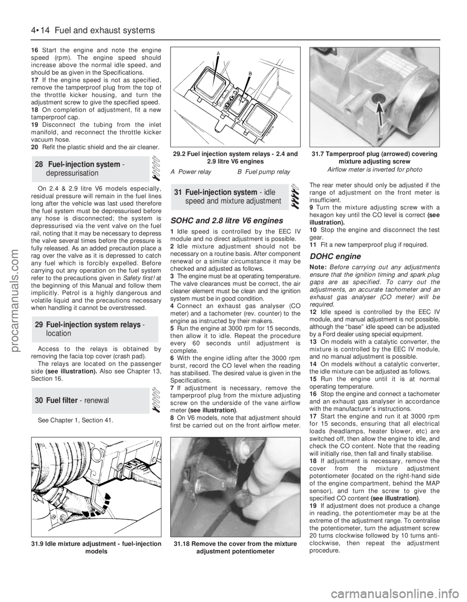
Access to the relays is obtained by
removing the facia top cover (crash pad).
The relays are located on the passenger
side(see illustration). Also see Chapter 13,
Section 16.
See Chapter 1, Section 41.
SOHC and 2.8 litre V6 engines
1Idle speed is controlled by the EEC IV
module and no direct adjustment is possible.
2Idle mixture adjustment should not be
necessary on a routine basis. After component
renewal or a similar circumstance it may be
checked and adjusted as follows.
3The engine must be at operating temperature.
The valve clearances must be correct, the air
cleaner element must be clean and the ignition
system must be in good condition.
4Connect an exhaust gas analyser (CO
meter) and a tachometer (rev. counter) to the
engine as instructed by their makers.
5Run the engine at 3000 rpm for 15 seconds,
then allow it to idle. Repeat the procedure
every 60 seconds until adjustment is
complete.
6With the engine idling after the 3000 rpm
burst, record the CO level when the reading
has stabilised. The desired value is given in the
Specifications.
7If adjustment is necessary, remove the
tamperproof plug from the mixture adjusting
screw on the underside of the vane airflow
meter (see illustration).
8On V6 models, note that adjustment should
first be carried out on the front airflow meter.The rear meter should only be adjusted if the
range of adjustment on the front meter is
insufficient.
9Turn the mixture adjusting screw with a
hexagon key until the CO level is correct (see
illustration).
10Stop the engine and disconnect the test
gear.
11Fit a new tamperproof plug if required.
DOHC engine
Note: Before carrying out any adjustments
ensure that the ignition timing and spark plug
gaps are as specified. To carry out the
adjustments, an accurate tachometer and an
exhaust gas analyser (CO meter) will be
required.
12Idle speed is controlled by the EEC IV
module, and manual adjustment is not possible,
although the “base” idle speed can be adjusted
by a Ford dealer using special equipment.
13On models with a catalytic converter, the
mixture is controlled by the EEC IV module,
and no manual adjustment is possible.
14On models without a catalytic converter,
the idle mixture can be adjusted as follows.
15Run the engine until it is at normal
operating temperature.
16Stop the engine and connect a tachometer
and an exhaust gas analyser in accordance
with the manufacturer’s instructions.
17Start the engine and run it at 3000 rpm
for 15 seconds, ensuring that all electrical
loads (headlamps, heater blower, etc) are
switched off, then allow the engine to idle, and
check the CO content. Note that the reading
will initially rise, then fall and finally stabilise.
18If adjustment is necessary, remove the
cover from the mixture adjustment
potentiometer (located on the right-hand side
of the engine compartment, behind the MAP
sensor), and turn the screw to give the
specified CO content (see illustration).
19If adjustment does not produce a change
in reading, the potentiometer may be at the
extreme of the adjustment range. To centralise
the potentiometer, turn the adjustment screw
20 turns clockwise followed by 10 turns anti-
clockwise, then repeat the adjustment
procedure.
31Fuel-injection system - idle
speed and mixture adjustment
30Fuel filter - renewal
29Fuel-injection system relays -
location
28Fuel-injection system -
depressurisation
4•14Fuel and exhaust systems
31.18 Remove the cover from the mixture
adjustment potentiometer31.9 Idle mixture adjustment - fuel-injection
models
29.2 Fuel injection system relays - 2.4 and
2.9 litre V6 engines
A Power relayB Fuel pump relay
31.7 Tamperproof plug (arrowed) covering
mixture adjusting screw
Airflow meter is inverted for photo
procarmanuals.com
Page 128 of 255
2Disconnect the battery negative lead.
3Drain the cooling system (Chapter 3). Save
the coolant if it is fit for re-use.
4Disconnect the multi-plug from the sensor.
Pull on the plug, not on the wiring (see
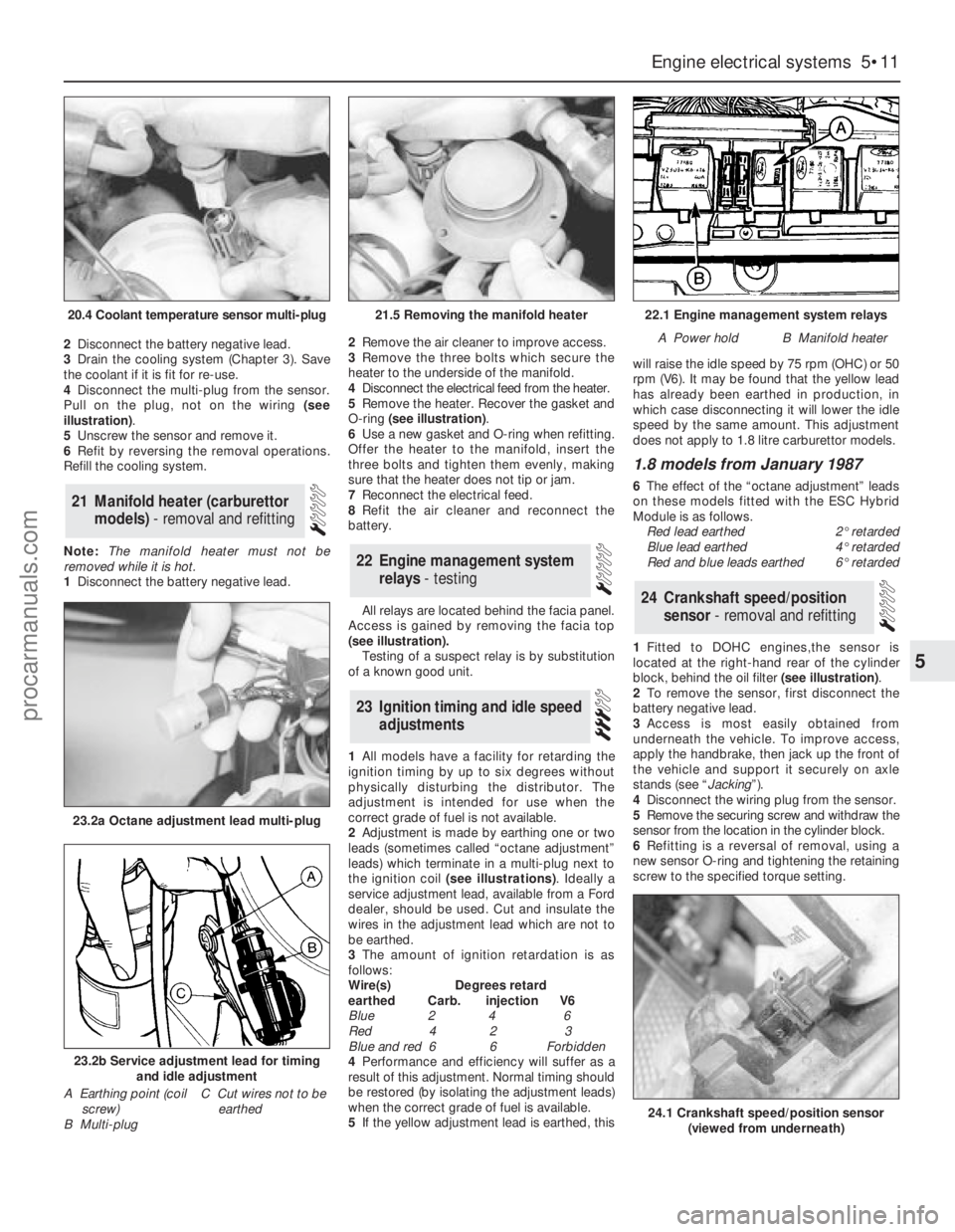
illustration).
5Unscrew the sensor and remove it.
6Refit by reversing the removal operations.
Refill the cooling system.
Note: The manifold heater must not be
removed while it is hot.
1Disconnect the battery negative lead. 2Remove the air cleaner to improve access.
3Remove the three bolts which secure the
heater to the underside of the manifold.
4Disconnect the electrical feed from the heater.
5Remove the heater. Recover the gasket and
O-ring (see illustration).
6Use a new gasket and O-ring when refitting.
Offer the heater to the manifold, insert the
three bolts and tighten them evenly, making
sure that the heater does not tip or jam.
7Reconnect the electrical feed.
8Refit the air cleaner and reconnect the
battery.
All relays are located behind the facia panel.
Access is gained by removing the facia top
(see illustration).
Testing of a suspect relay is by substitution
of a known good unit.
1All models have a facility for retarding the
ignition timing by up to six degrees without
physically disturbing the distributor. The
adjustment is intended for use when the
correct grade of fuel is not available.
2Adjustment is made by earthing one or two
leads (sometimes called “octane adjustment”
leads) which terminate in a multi-plug next to
the ignition coil (see illustrations). Ideally a
service adjustment lead, available from a Ford
dealer, should be used. Cut and insulate the
wires in the adjustment lead which are not to
be earthed.
3The amount of ignition retardation is as
follows:
Wire(s) Degrees retard
earthed Carb. injection V6
Blue 2 4 6
Red 4 2 3
Blue and red 6 6 Forbidden
4Performance and efficiency will suffer as a
result of this adjustment. Normal timing should
be restored (by isolating the adjustment leads)
when the correct grade of fuel is available.
5If the yellow adjustment lead is earthed, thiswill raise the idle speed by 75 rpm (OHC) or 50
rpm (V6). It may be found that the yellow lead
has already been earthed in production, in
which case disconnecting it will lower the idle
speed by the same amount. This adjustment
does not apply to 1.8 litre carburettor models.
1.8 models from January 1987
6The effect of the “octane adjustment” leads
on these models fitted with the ESC Hybrid
Module is as follows.
Red lead earthed2°retarded
Blue lead earthed4°retarded
Red and blue leads earthed6°retarded
1Fitted to DOHC engines,the sensor is
located at the right-hand rear of the cylinder
block, behind the oil filter (see illustration).
2To remove the sensor, first disconnect the
battery negative lead.
3Access is most easily obtained from
underneath the vehicle. To improve access,
apply the handbrake, then jack up the front of
the vehicle and support it securely on axle
stands (see “Jacking”).
4Disconnect the wiring plug from the sensor.
5Remove the securing screw and withdraw the
sensor from the location in the cylinder block.
6Refitting is a reversal of removal, using a
new sensor O-ring and tightening the retaining
screw to the specified torque setting.
24Crankshaft speed/position
sensor - removal and refitting
23Ignition timing and idle speed
adjustments
22Engine management system
relays - testing
21Manifold heater (carburettor
models) - removal and refitting
Engine electrical systems 5•11
5
20.4 Coolant temperature sensor multi-plug21.5 Removing the manifold heater22.1 Engine management system relays
A Power holdB Manifold heater
23.2a Octane adjustment lead multi-plug
23.2b Service adjustment lead for timing
and idle adjustment
A Earthing point (coil
screw)
B Multi-plugC Cut wires not to be
earthed
24.1 Crankshaft speed/position sensor
(viewed from underneath)
procarmanuals.com
Page 241 of 255
REF•6
Engine fails to rotate when attempting to start
m mBattery terminal connections loose or corroded (Chapter 1).
m mBattery discharged or faulty (Chapter 5).
m mBroken, loose or disconnected wiring in the starting circuit
(Chapter 5).
m mDefective starter solenoid or switch (Chapter 5).
m mDefective starter motor (Chapter 5).
m mStarter pinion or flywheel/driveplate ring gear teeth loose or broken
(Chapters 2 or 5).
m mEngine earth strap broken or disconnected.
Starter motor turns engine slowly
m
mPartially-discharged battery (recharge, use jump leads, or push
start) (Chapter 5).
m mBattery terminals loose or corroded (Chapter 1).
m mBattery earth to body defective (Chapter 5).
m mEngine earth strap loose.
m mStarter motor (or solenoid) wiring loose (Chapter 5).
m mStarter motor internal fault (Chapter 5).
Engine rotates, but will not start
m
mFuel pump inertia switch tripped (electric pump) (Chapter 4).
m mFuel tank empty.
m mBattery discharged (engine rotates slowly) (Chapter 5).
m mBattery terminal connections loose or corroded (Chapter 1).
m mIgnition components damp or damaged (Chapters 1 and 5).
m mBroken, loose or disconnected wiring in the ignition circuit
(Chapters 1 and 5).
m mWorn, faulty or incorrectly-gapped spark plugs (Chapter 1).
m mFuel injection system fault (Chapter 4).
m mMajor mechanical failure (eg broken timing chain) (Chapter 2).
Engine difficult to start when cold
m
mBattery discharged (Chapter 5).
m mBattery terminal connections loose or corroded (Chapter 1).
m mWorn, faulty or incorrectly-gapped spark plugs (Chapter 1).
m mFuel injection system fault (Chapter 4).
m mOther ignition system fault (Chapters 1 and 5).
m mLow cylinder compressions (Chapter 2).
Engine difficult to start when hot
m
mAir filter element dirty or clogged (Chapter 1).
m mFuel injection system fault (Chapter 4).
m mLow cylinder compressions (Chapter 2).
Starter motor noisy or excessively-rough in
engagement
m mStarter pinion or flywheel/driveplate ring gear teeth loose or broken
(Chapters 2 or 5).
m mStarter motor mounting bolts loose or missing (Chapter 5).
m mStarter motor internal components worn or damaged (Chapter 5).
Engine starts, but stops immediately
m
mLoose or faulty electrical connections in the ignition circuit
(Chapters 1 and 5).
m mVacuum leak at the throttle body or inlet manifold (Chapter 4).
m mFuel injection system fault (Chapter 4).
Engine idles erratically
m
mCarburettor stepper motor plunger dirty (2.0 litre only) (Chapter 5)
m mIncorrectly-adjusted idle speed (Chapter 4).
m mAir filter element clogged (Chapter 1).
m mVacuum leak at the throttle body, inlet manifold or associated hoses
(Chapter 4).
m mWorn, faulty or incorrectly-gapped spark plugs (Chapter 1).
m mUneven or low cylinder compressions (Chapter 2).
m mCamshaft lobes worn (Chapter 2).
m mFuel injection system fault (Chapter 4).
Engine misfires at idle speed
m
mWorn, faulty or incorrectly-gapped spark plugs (Chapter 1).
m mFaulty spark plug HT leads (Chapter 5).
m mVacuum leak at the throttle body, inlet manifold or associated hoses
(Chapter 4).
m mFuel injection system fault (Chapter 4).
m mDistributor cap cracked or tracking internally, where applicable
(Chapter 5).
m mUneven or low cylinder compressions (Chapter 2).
m mDisconnected, leaking, or perished crankcase ventilation hoses
(Chapter 4).
Fault Finding
spark plugs may only be pointers to some underlying fault.
The pages which follow provide an easy-reference guide to the more
common problems which may occur during the operation of the
vehicle. These problems and their possible causes are grouped under
headings denoting various components or systems, such as Engine,
Cooling system, etc. The Chapter and/or Section which deals with the
problem is also shown in brackets. Whatever the fault, certain basic
principles apply. These are as follows:
Verify the fault. This is simply a matter of being sure that you know
what the symptoms are before starting work. This is particularly
important if you are investigating a fault for someone else, who may
not have described it very accurately.
Don’t overlook the obvious. For example, if the vehicle won’t start, is
there fuel in the tank? (Don’t take anyone else’s word on this particular
point, and don’t trust the fuel gauge either!) If an electrical fault isindicated, look for loose or broken wires before digging out the test
gear.
Cure the disease, not the symptom. Substituting a flat battery with a
fully-charged one will get you off the hard shoulder, but if the
underlying cause is not attended to, the new battery will go the same
way. Similarly, changing oil-fouled spark plugs for a new set will get
you moving again, but remember that the reason for the fouling (if it
wasn’t simply an incorrect grade of plug) will have to be established
and corrected.
Don’t take anything for granted. Particularly, don’t forget that a
“new” component may itself be defective (especially if it’s been rattling
around in the boot for months), and don’t leave components out of a
fault diagnosis sequence just because they are new or recently-fitted.
When you do finally diagnose a difficult fault, you’ll probably realise
that all the evidence was there from the start.
1 Engine
procarmanuals.com
Page 242 of 255
Engine misfires throughout the driving speed range
m mFuel filter choked (Chapter 1).
m mFuel pump faulty, or delivery pressure low (Chapter 4).
m mFuel tank vent blocked, or fuel pipes restricted (Chapter 4).
m mVacuum leak at the throttle body, inlet manifold or associated hoses
(Chapter 4).
m mWorn, faulty or incorrectly-gapped spark plugs (Chapter 1).
m mFaulty spark plug HT leads (Chapter 5).
m mDistributor cap cracked or tracking internally (Chapter 5).
m mFaulty ignition coil (Chapter 5).
m mUneven or low cylinder compressions (Chapter 2).
m mFuel injection system fault (Chapter 4).
Engine hesitates on acceleration
m
mWorn, faulty or incorrectly-gapped spark plugs (Chapter 1).
m mVacuum leak at the throttle body, inlet manifold or associated hoses
(Chapter 4).
m mFuel injection system fault (Chapter 4).
Engine stalls
m
mVacuum leak at the throttle body, inlet manifold or associated hoses
(Chapter 4).
m mFuel filter choked (Chapter 1).
m mFuel pump faulty, or delivery pressure low (Chapter 4).
m mFuel tank vent blocked, or fuel pipes restricted (Chapter 4).
m mFuel injection system fault (Chapter 4).
Engine lacks power
m
mFuel filter choked (Chapter 1).
m mFuel pump faulty, or delivery pressure low (Chapter 4).
m mUneven or low cylinder compressions (Chapter 2).
m mWorn, faulty or incorrectly-gapped spark plugs (Chapter 1).
m mVacuum leak at the throttle body, inlet manifold or associated hoses
(Chapter 4).
m mFuel injection system fault (Chapter 4).
m mBrakes binding (Chapters 1 and 10).
m mClutch slipping (Chapter 6).
Engine backfires
m
mVacuum leak at the throttle body, inlet manifold or associated hoses
(Chapter 4).
m mFuel injection system fault (Chapter 4).
Oil pressure warning light illuminated with engine
running
m mLow oil level, or incorrect oil grade (Chapter 1).
m mFaulty oil pressure sensor (Chapter 2).
m mWorn engine bearings and/or oil pump (Chapter 2).
m mExcessively high engine operating temperature (Chapter 3).
m mOil pressure relief valve defective (Chapter 2).
m mOil pick-up strainer clogged (Chapter 2).
Note:Low oil pressure in a high-mileage engine at tickover is not
necessarily a cause for concern. Sudden pressure loss at speed is far
more significant. In any event, check the gauge or warning light sender
before condemning the engine.
Engine runs-on after switching off
m mExcessive carbon build-up in engine (Chapter 2).
m mExcessively high engine operating temperature (Chapter 3).
Engine noises
Pre-ignition (pinking) or knocking during acceleration or
under load
m mIgnition timing incorrect/ignition system fault (Chapters 1 and 5).
m mIncorrect grade of spark plug (Chapter 1).
m mIncorrect grade of fuel (Chapter 1).
m mVacuum leak at throttle body, inlet manifold or associated hoses
(Chapter 4).
m mExcessive carbon build-up in engine (Chapter 2).
m mFuel injection system fault (Chapter 4).
Whistling or wheezing noises
m
mLeaking inlet manifold or throttle body gasket (Chapter 4).
m mLeaking exhaust manifold gasket (Chapter 4).
m mLeaking vacuum hose (Chapters 4 and 10).
m mBlowing cylinder head gasket (Chapter 2).
Tapping or rattling noises
m
mWorn valve gear, timing chain, camshaft or hydraulic tappets
(Chapter 2).
m mAncillary component fault (water pump, alternator, etc) (Chapters 3,
5, etc).
Knocking or thumping noises
m mWorn big-end bearings (regular heavy knocking, perhaps less under
load) (Chapter 2).
m mWorn main bearings (rumbling and knocking, perhaps worsening
under load) (Chapter 2).
m mPiston slap (most noticeable when cold) (Chapter 2).
m mAncillary component fault (water pump, alternator, etc) (Chapters 3,
5, etc).
REF•7Fault Finding
2Cooling system
Overheating
m
mAuxiliary drivebelt broken or incorrectly adjusted (Chapter 1).
m mInsufficient coolant in system (Chapter 1).
m mThermostat faulty (Chapter 3).
m mRadiator core blocked, or grille restricted (Chapter 3).
m mElectric cooling fan or thermostatic switch faulty (Chapter 3).
m mViscous-coupled fan faulty (Chapter 3).
m mIgnition timing incorrect, or ignition system fault (Chapters 1 and 5).
m mInaccurate temperature gauge sender unit (Chapter 3).
m mAirlock in cooling system (Chapter 3).
Overcooling
m
mThermostat faulty (Chapter 3).
m mInaccurate temperature gauge sender unit (Chapter 3).
External coolant leakage
m
mDeteriorated or damaged hoses or hose clips (Chapter 1).
m mRadiator core or heater matrix leaking (Chapter 3).
m mPressure cap faulty (Chapter 3).
m mWater pump internal seal leaking (Chapter 3).
m mWater pump-to-block seal leaking (Chapter 3).
m mBoiling due to overheating (Chapter 3).
m mCore plug leaking (Chapter 2).
Internal coolant leakage
m
mLeaking cylinder head gasket (Chapter 2).
m mCracked cylinder head or cylinder block (Chapter 2).
Corrosion
m
mInfrequent draining and flushing (Chapter 1).
m mIncorrect coolant mixture or inappropriate coolant type (Chapter 1).
procarmanuals.com
Page 243 of 255
REF•8
Pedal travels to floor - no pressure or very little
resistance
m m
Badly stretched or broken cable (Chapter 6).m
mStripped pawl on pedal (Chapter 6).m
mBroken clutch release bearing or arm (Chapter 6).m
mBroken diaphragm spring in clutch pressure plate (Chapter 6).
Clutch fails to disengage (unable to select gears)
m m
Cable free play excessive (Chapter 6).m
mClutch driven plate sticking on gearbox input shaft splines (Chapter 6).m
mClutch driven plate sticking to flywheel or pressure plate (Chapter 6).m
mFaulty pressure plate assembly (Chapter 6).m
mClutch release mechanism worn or incorrectly assembled (Chapter 6).
Clutch slips (engine speed increases, with no
increase in vehicle speed)
m m
Clutch driven plate linings excessively worn (Chapter 6).m
mClutch driven plate linings contaminated with oil or grease (Chapter 6).m
mFaulty pressure plate or weak diaphragm spring (Chapter 6).
Judder as clutch is engaged
m m
Clutch driven plate linings contaminated with oil or grease (Chapter 6).m
mClutch driven plate linings excessively worn (Chapter 6).m
mFaulty or distorted pressure plate or diaphragm spring (Chapter 6).m
mWorn or loose engine or gearbox mountings (Chapter 2).m
mClutch driven plate hub or gearbox input shaft splines worn
(Chapter 6).
Noise when depressing or releasing clutch pedal
m m
Worn clutch release bearing (Chapter 6).m
mWorn or dry clutch pedal pivot (Chapter 6).m
mFaulty pressure plate assembly (Chapter 6).m
mPressure plate diaphragm spring broken (Chapter 6).m
mBroken clutch driven plate cushioning springs (Chapter 6).
Excessive fuel consumption
m
mAir filter element dirty or clogged (Chapter 1).
m mFuel injection system fault (Chapter 4).
m mIgnition timing incorrect or ignition system fault (Chapters 1 and 5).
m mBrakes binding (Chapter 10).
m mTyres under-inflated (Chapter 1).
Fuel leakage and/or fuel odour
m
mDamaged fuel tank, pipes or connections (Chapters 1 and 4).
Excessive noise or fumes from exhaust system
m
mLeaking exhaust system or manifold joints (Chapters 1 and 4).
m mLeaking, corroded or damaged silencers or pipe (Chapters 1 and 4).
m mBroken mountings causing body or suspension contact (Chapter 4).
Fault Finding
4Clutch
5Manual gearbox
Noisy in neutral with engine running
m m
Input shaft bearings worn (noise apparent with clutch pedal
released, but not when depressed) (Chapter 7A).*
m mClutch release bearing worn (noise apparent with clutch pedal
depressed, possibly less when released) (Chapter 6).
Noisy in one particular gear
m m
Worn, damaged or chipped gear teeth (Chapter 7A).*
Difficulty engaging gears
m m
Clutch fault (Chapter 6).m
mWorn or damaged gear linkage (Chapter 7A).m
mWorn synchroniser units (Chapter 7A).*
Jumps out of gear
m m
Worn or damaged gear linkage (Chapter 7A).m
mWorn synchroniser units (Chapter 7A).*m
mWorn selector forks (Chapter 7A).*
Vibration
m m
Lack of oil (Chapter 1).m
mWorn bearings (Chapter 7A).*
Lubricant leaks
m m
Leaking oil seal (Chapter 7A).m
mLeaking housing joint (Chapter 7A).*
*Although the corrective action necessary to remedy the symptoms
described is beyond the scope of the home mechanic, the above
information should be helpful in isolating the cause of the condition, so
that the owner can communicate clearly with a professional mechanic.
6Automatic transmission
Note:Due to the complexity of the automatic transmission, it is difficult
for the home mechanic to properly diagnose and service this unit. For
problems other than the following, the vehicle should be taken to a
dealer service department or automatic transmission specialist.
Fluid leakage
m m
Automatic transmission fluid is usually deep red in colour. Fluid
leaks should not be confused with engine oil, which can easily be
blown onto the transmission by air flow.
m mTo determine the source of a leak, first remove all built-up dirt and
grime from the transmission housing and surrounding areas, using a
degreasing agent or by steam-cleaning. Drive the vehicle at low speed,
so that air flow will not blow the leak far from its source. Raise and
support the vehicle, and determine where the leak is coming from. The
following are common areas of leakage:
a)Fluid pan ( transmission “sump”).
b)Dipstick tube (Chapter 1).
c)Transmission-to-fluid cooler fluid pipes/unions (Chapter 7B).
3Fuel and exhaust systems
procarmanuals.com