1985 FORD GRANADA coolant level
[x] Cancel search: coolant levelPage 196 of 255

17Refit by inserting the switch into the
grommet - use a new grommet if necessary -
and screwing on the retaining ring. Reconnect
the multi-plug and top-up the cooling system.
Washer fluid level switch
18Syphon the fluid out of the washer
reservoir until the level is below the switch.
19Disconnect the switch multi-plug.
Carefully prise the switch out of its grommet
and remove it. Note how flats on the grommet
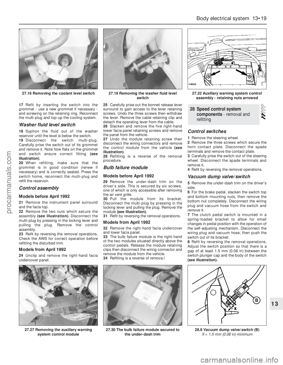
and switch ensure correct fitting (see
illustration).
20When refitting, make sure that the
grommet is in good condition (renew if
necessary) and is correctly seated. Press the
switch home, reconnect the multi-plug and
refill the reservoir.
Control assembly
Models before April 1992
21Remove the instrument panel surround
and the facia top.
22Remove the two nuts which secure the
assembly(see illustration).Disconnect the
multi-plug by pressing in the locking lever and
pulling the plug. Remove the control
assembly.
23Refit by reversing the removal operations.
Check the AWS for correct operation before
refitting the disturbed trim.
Models from April 1992
24Unclip and remove the right-hand facia
undercover panel.25Carefully prise out the bonnet release lever
surround to gain access to the lever retaining
screws. Undo the three screws then withdraw
the lever. Remove the cable retaining clip and
detach the operating lever from the cable.
26Slacken and remove the five right-hand
lower facia panel retaining screws and remove
the panel from the vehicle.
27Undo the module retaining screw then
disconnect the wiring connectors and remove
the control module from the vehicle (see
illustration).
28Refitting is a reverse of the removal
procedure.
Bulb failure module
Models before April 1992
29Remove the under-dash trim on the
driver’s side. This is secured by six screws,
one of which is only accessible after removing
the air vent grille.
30Pull the module from its bracket.
Disconnect the multi-plug by pressing in the
locking lever and pulling the plug. Remove the
module (see illustration).
31Refit by reversing the removal operations.
Models from April 1992
32Remove the right-hand facia undercover
and lower facia panel.
33The bulb failure module is the right-hand
of the two modules situated directly above the
control pedals. Release the module retaining
clips then disconnect the wiring connector and
remove the module from the vehicle.
34Refitting is a reverse of remova.l
Control switches
1Remove the steering wheel.
2Remove the three screws which secure the
horn contact plate. Disconnect the spade
terminals and remove the contact plate.
3Carefully prise the switch out of the steering
wheel. Disconnect the spade terminals and
remove it.
4Refit by reversing the removal operations.
Vacuum dump valve/switch
5Remove the under-dash trim on the driver’s
side.
6For the brake pedal, slacken the switch top
and bottom mounting nuts, then remove the
bottom nut completely. Disconnect the wiring
plug and vacuum hose from the switch and
remove it.
7The clutch pedal switch is mounted in a
spring-loaded bracket to allow for small
changes in pedal position with the operation of
the self-adjusting mechanism. Disconnect the
wiring plug and vacuum hose, then push the
switch out of its bracket.
8Refit by reversing the removal operations.
Adjust the switch position so that there is a
gap of at least 1.5 mm (0.06 in) between the
switch plunger cap and the body of the switch
(see illustration).
28Speed control system
components - removal and
refitting
Body electrical system 13•19
13
27.16 Removing the coolant level switch27.19 Removing the washer fluid level
switch27.22 Auxiliary warning system control
assembly - retaining nuts arrowed
27.27 Removing the auxiliary warning
system control module27.30 The bulb failure module secured to
the under-dash trim28.8 Vacuum dump valve/switch (B)
X = 1.5 mm (0.06 in) minimum
procarmanuals.com
Page 242 of 255

Engine misfires throughout the driving speed range
m mFuel filter choked (Chapter 1).
m mFuel pump faulty, or delivery pressure low (Chapter 4).
m mFuel tank vent blocked, or fuel pipes restricted (Chapter 4).
m mVacuum leak at the throttle body, inlet manifold or associated hoses
(Chapter 4).
m mWorn, faulty or incorrectly-gapped spark plugs (Chapter 1).
m mFaulty spark plug HT leads (Chapter 5).
m mDistributor cap cracked or tracking internally (Chapter 5).
m mFaulty ignition coil (Chapter 5).
m mUneven or low cylinder compressions (Chapter 2).
m mFuel injection system fault (Chapter 4).
Engine hesitates on acceleration
m
mWorn, faulty or incorrectly-gapped spark plugs (Chapter 1).
m mVacuum leak at the throttle body, inlet manifold or associated hoses
(Chapter 4).
m mFuel injection system fault (Chapter 4).
Engine stalls
m
mVacuum leak at the throttle body, inlet manifold or associated hoses
(Chapter 4).
m mFuel filter choked (Chapter 1).
m mFuel pump faulty, or delivery pressure low (Chapter 4).
m mFuel tank vent blocked, or fuel pipes restricted (Chapter 4).
m mFuel injection system fault (Chapter 4).
Engine lacks power
m
mFuel filter choked (Chapter 1).
m mFuel pump faulty, or delivery pressure low (Chapter 4).
m mUneven or low cylinder compressions (Chapter 2).
m mWorn, faulty or incorrectly-gapped spark plugs (Chapter 1).
m mVacuum leak at the throttle body, inlet manifold or associated hoses
(Chapter 4).
m mFuel injection system fault (Chapter 4).
m mBrakes binding (Chapters 1 and 10).
m mClutch slipping (Chapter 6).
Engine backfires
m
mVacuum leak at the throttle body, inlet manifold or associated hoses
(Chapter 4).
m mFuel injection system fault (Chapter 4).
Oil pressure warning light illuminated with engine
running
m mLow oil level, or incorrect oil grade (Chapter 1).
m mFaulty oil pressure sensor (Chapter 2).
m mWorn engine bearings and/or oil pump (Chapter 2).
m mExcessively high engine operating temperature (Chapter 3).
m mOil pressure relief valve defective (Chapter 2).
m mOil pick-up strainer clogged (Chapter 2).
Note:Low oil pressure in a high-mileage engine at tickover is not
necessarily a cause for concern. Sudden pressure loss at speed is far
more significant. In any event, check the gauge or warning light sender
before condemning the engine.
Engine runs-on after switching off
m mExcessive carbon build-up in engine (Chapter 2).
m mExcessively high engine operating temperature (Chapter 3).
Engine noises
Pre-ignition (pinking) or knocking during acceleration or
under load
m mIgnition timing incorrect/ignition system fault (Chapters 1 and 5).
m mIncorrect grade of spark plug (Chapter 1).
m mIncorrect grade of fuel (Chapter 1).
m mVacuum leak at throttle body, inlet manifold or associated hoses
(Chapter 4).
m mExcessive carbon build-up in engine (Chapter 2).
m mFuel injection system fault (Chapter 4).
Whistling or wheezing noises
m
mLeaking inlet manifold or throttle body gasket (Chapter 4).
m mLeaking exhaust manifold gasket (Chapter 4).
m mLeaking vacuum hose (Chapters 4 and 10).
m mBlowing cylinder head gasket (Chapter 2).
Tapping or rattling noises
m
mWorn valve gear, timing chain, camshaft or hydraulic tappets
(Chapter 2).
m mAncillary component fault (water pump, alternator, etc) (Chapters 3,
5, etc).
Knocking or thumping noises
m mWorn big-end bearings (regular heavy knocking, perhaps less under
load) (Chapter 2).
m mWorn main bearings (rumbling and knocking, perhaps worsening
under load) (Chapter 2).
m mPiston slap (most noticeable when cold) (Chapter 2).
m mAncillary component fault (water pump, alternator, etc) (Chapters 3,
5, etc).
REF•7Fault Finding
2Cooling system
Overheating
m
mAuxiliary drivebelt broken or incorrectly adjusted (Chapter 1).
m mInsufficient coolant in system (Chapter 1).
m mThermostat faulty (Chapter 3).
m mRadiator core blocked, or grille restricted (Chapter 3).
m mElectric cooling fan or thermostatic switch faulty (Chapter 3).
m mViscous-coupled fan faulty (Chapter 3).
m mIgnition timing incorrect, or ignition system fault (Chapters 1 and 5).
m mInaccurate temperature gauge sender unit (Chapter 3).
m mAirlock in cooling system (Chapter 3).
Overcooling
m
mThermostat faulty (Chapter 3).
m mInaccurate temperature gauge sender unit (Chapter 3).
External coolant leakage
m
mDeteriorated or damaged hoses or hose clips (Chapter 1).
m mRadiator core or heater matrix leaking (Chapter 3).
m mPressure cap faulty (Chapter 3).
m mWater pump internal seal leaking (Chapter 3).
m mWater pump-to-block seal leaking (Chapter 3).
m mBoiling due to overheating (Chapter 3).
m mCore plug leaking (Chapter 2).
Internal coolant leakage
m
mLeaking cylinder head gasket (Chapter 2).
m mCracked cylinder head or cylinder block (Chapter 2).
Corrosion
m
mInfrequent draining and flushing (Chapter 1).
m mIncorrect coolant mixture or inappropriate coolant type (Chapter 1).
procarmanuals.com
Page 252 of 255

A
ABS module - 10•11
Accelerator pump diaphragm renewal - 4•12
Accessory shops - 0•8
Acknowledgements - 0•4
Aerial pre-amplifier - 13•22
Air bags - 0•5
Air charge temperature sensor - 5•12
Air cleaner - 1•16, 4•4
Air conditioner - 1•14, 1•15, 3•2, 3•9
Air temperature sensor - 13•18
Alarm signal buzzer - 13•23
Alarm system horn - 13•23
Alternator - 3•7, 5•4
Anti-roll bar - 11•9, 11•12
Anti-theft alarm - 13•22, 13•23
Antifreeze mixture - 3•2
Asbestos - 0•5
Ashtray light - 13•8
Automatic choke - 1•16, 4•10, 4•12
Automatic transmission- 1•11, 1•15, 2B•6,
2B•7, 7B•1et seq, REF•8
Automatic transmission brake band
adjustment - 1•19
Automatic transmission selector light - 13•9
Auxiliary drivebelt - 1•12
Auxiliary driving light - 13•4, 13•6
Auxiliary shaft - 2A•9, 2A•14, 2A•16
Auxiliary warning system components - 13•18
B
Backrests - 12•19, 12•18
Battery - 0•5, 1•8, 1•13, 5•3, 5•4
Battery will not hold a charge for more than
a few days - REF•11
Bleeding the brakes - 10•3
Bleeding the power steering - 11•3
Body corrosion - 0•14
Body damage - 12•2, 12•4
Body electrical system- 13•1et seq
Bodywork and fittings- 12•1et seq
Bodywork repairs - 12•3
Bonnet - 12•4, 12•9
Bonnet release cable - 12•6
Booster battery (jump) starting - 0•10
Boot lid - 12•5
Boot lid lock barrel - 12•7
Brake band adjustment - 1•19, 7B•3
Brake fluid - 1•7, 1•19
Brake hydraulic system - 10•3
Brake pedal effort high to stop vehicle - REF•9
Brake pedal feels spongy when depressed
- REF•9
Brake pedal pulsates when braking hard -
REF•10
Brake pedal travel excessive - REF•9
Brake pipe and hoses - 1•15, 10•10
Brakes binding - REF•10
Braking system- 0•13, 10•1et seq, REF•9
Bulb failure module - 13•19
Bulbs - 13•4, 13•7
Bumper - 12•10, 12•11
Burning - 0•5
C
Cables - 3•8, 4•7, 6•3, 7B•3, 10•11
Caliper - 10•5, 10•6
Camshaft - 2A•7, 2A•14, 2A•17, 2B•14,
2C•12, 2C•13, 2C•15
Camshaft drivebelt - 1•20
Capacities - 1•3
Carbon canister - 4•23
Carburettor stepper motor - 5•10
Catalytic converter - 4•4
Central locking motor - 13•13
Central locking system inoperative, or
unsatisfactory in operation - REF•11
Centre console - 12•15
Cigarette lighter - 13•10
Clock - 13•9, 13•10
Clutch- 6•1et seq, REF•8
Clutch fails to disengage (unable to select
gears) - REF•8
Clutch pedal travels to floor - REF•8
Clutch release bearing and arm - 6•4
Clutch slips (engine speed increases, with
no increase in vehicle speed) - REF•8
CO emissions (mixture) - 0•14
Compliance bushes - 11•9
Compression test - 2A•20, 2B•18, 2C•21
Compressor drivebelt - 3•9
Computer module and bulb - 13•18
Condenser fan and motor - 3•10
Connecting rods - 2A•11, 2A•13, 2A•15,
2B•17, 2C•12, 2C•14, 2C•16
Console light - 13•9
Contents - 0•2
Control assembly - 13•19
Control module - 10•13
Control switches - 13•19
Control units - 13•13
Conversion factors - REF•16
Coolant - 1•6, 1•20
Coolant hoses - 2C•7
Coolant leakage - REF•7
Coolant level switch - 13•18
Coolant temperature sensor - 5•10
Cooling, heating and ventilation systems-
3•1 et seq, REF•7
Corrosion - REF•7
Courtesy light - 13•7
Crankcase ventilation system - 1•19,
2A•12, 2B•3, 2C•15
Crankshaft and bearings - 2A•11, 2A•12,
2A•15, 2B•17, 2B•18, 2C•12, 2C•14,
2C•15
Crankshaft oil seals - 2A•10, 2B•15, 2C•12
Crankshaft speed/position sensor - 5•11
Crossmember insulator - 11•12
Crushing - 0•5
Cushion - 12•18
Cylinder block and bores - 2A•13
Cylinder bores - 2C•14
Cylinder head - 2A•6, 2A•8, 2A•14, 2A•17,
2B•10, 2B•11, 2B•14, 2C•8, 2C•13,
2C•19
D
De-ice thermostat - 3•10
Decarbonising - 2A•14
Dents in bodywork - 12•2
Direction indicator - 13•5, 13•11
Discs - 10•3, 10•4, 10•8
Distributor - 5•5
Door exterior handle - 12•6
Door interior trim panel - 12•7
Door latch assembly - 12•6
Door lights - 13•7
Door lock barrel - 12•6
Door pillar switch - 13•12
Door speakers - 13•21
Door striker plate - 12•6
Door switch - 13•18
Door weatherstrip - 12•7
Door window - 12•8, 12•9
Doors - 0•12, 12•4, 12•7, 12•8, 12•9, 12•10
Downshift mechanism - 7B•3
Drivebelts - 1•12, 1•20, 3•7, 3•9, 11•6
Driveshaft - 1•15, 9•3
Drivetrain - 1•16
E
Earth fault - 13•4
EEC IV module - 5•9
Electric shock - 0•5
Electric windows inoperative, or
unsatisfactory in operation - REF•11
Electrical system - 0•12, 1•8, REF•10
Electronic ignition systems - 5•3
Engine- 2A•1 et seq, 2B•1 et seq, 2C•1 et
seq, REF•6
Engine backfires - REF•7
Engine bay light - 13•8
Engine difficult to start - REF•6
Engine dismantling - 2B•8
Engine electrical systems- 5•1et seq
Engine fails to rotate when attempting to
start - REF•6
Engine hesitates on acceleration - REF•7
Engine idles erratically - REF•6
Engine lacks power - REF•7
Engine management control module - 5•9
Engine management system relays - 5•11
Engine misfires - REF•6, REF•7
Engine mountings - 2A•11, 2B•8, 2C•12
Engine oil and filter - 1•6, 1•9
Engine rotates, but will not start - REF•6
Engine runs-on after switching off - REF•7
Engine stalls - REF•7
Engine starts, but stops immediately -
REF•6
Engine will not start in any gear, or starts in
gears other than Park or Neutral -
REF•9
Entertainment console - 13•22
Environmental considerations - REF•4
ESC II module - 5•3, 5•9
Exhaust emission checks - 0•14
Exhaust gas oxygen (HEGO) sensor - 4•22
Exhaust manifold(s) - 4•21
Exhaust system - 0•13, 1•10, 4•22
Expansion tank - 3•7
IND•1Index
Note: References throughout this index are in the form - “Chapter number” • “page number”
procarmanuals.com