1985 FORD GRANADA coolant level
[x] Cancel search: coolant levelPage 104 of 255
8Remove the drill and the rubber band.
9Refit the heat shield, making sure it is
properly located.
10Refit the bi-metal housing, engaging the
end of the spring with the choke valve lever.
Fit the three screws, position the housing in its
original alignment (paragraph 4) and tighten
the screws.
11If the bi-metal housing alignment has been
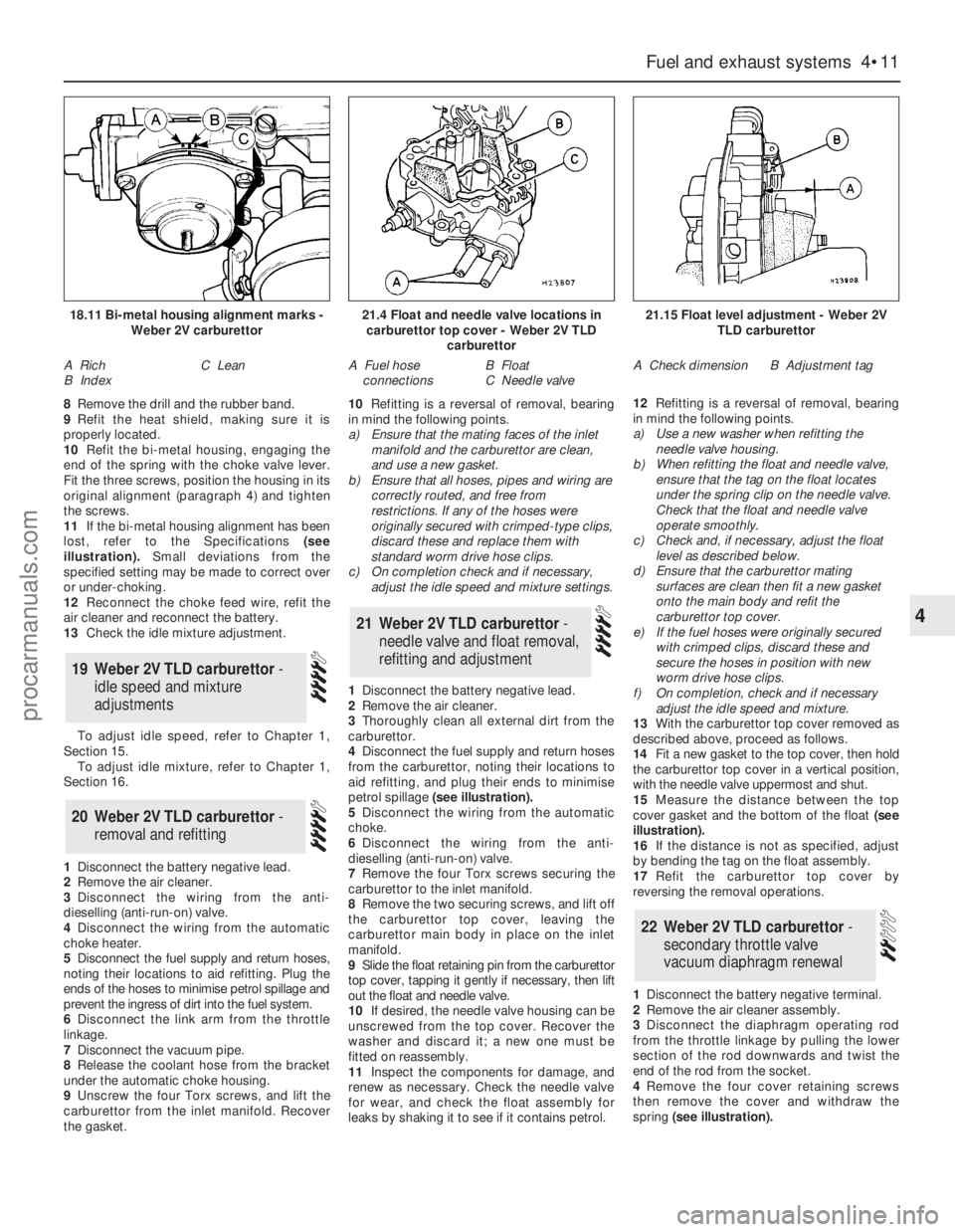
lost, refer to the Specifications(see
illustration).Small deviations from the
specified setting may be made to correct over
or under-choking.
12Reconnect the choke feed wire, refit the
air cleaner and reconnect the battery.
13Check the idle mixture adjustment.
To adjust idle speed, refer to Chapter 1,
Section 15.
To adjust idle mixture, refer to Chapter 1,
Section 16.
1Disconnect the battery negative lead.
2Remove the air cleaner.
3Disconnect the wiring from the anti-
dieselling (anti-run-on) valve.
4Disconnect the wiring from the automatic
choke heater.
5Disconnect the fuel supply and return hoses,
noting their locations to aid refitting. Plug the
ends of the hoses to minimise petrol spillage and
prevent the ingress of dirt into the fuel system.
6Disconnect the link arm from the throttle
linkage.
7Disconnect the vacuum pipe.
8Release the coolant hose from the bracket
under the automatic choke housing.
9Unscrew the four Torx screws, and lift the
carburettor from the inlet manifold. Recover
the gasket.10Refitting is a reversal of removal, bearing
in mind the following points.
a)Ensure that the mating faces of the inlet
manifold and the carburettor are clean,
and use a new gasket.
b)Ensure that all hoses, pipes and wiring are
correctly routed, and free from
restrictions. If any of the hoses were
originally secured with crimped-type clips,
discard these and replace them with
standard worm drive hose clips.
c)On completion check and if necessary,
adjust the idle speed and mixture settings.
1Disconnect the battery negative lead.
2Remove the air cleaner.
3Thoroughly clean all external dirt from the
carburettor.
4Disconnect the fuel supply and return hoses
from the carburettor, noting their locations to
aid refitting, and plug their ends to minimise
petrol spillage (see illustration).
5Disconnect the wiring from the automatic
choke.
6Disconnect the wiring from the anti-
dieselling (anti-run-on) valve.
7Remove the four Torx screws securing the
carburettor to the inlet manifold.
8Remove the two securing screws, and lift off
the carburettor top cover, leaving the
carburettor main body in place on the inlet
manifold.
9Slide the float retaining pin from the carburettor
top cover, tapping it gently if necessary, then lift
out the float and needle valve.
10If desired, the needle valve housing can be
unscrewed from the top cover. Recover the
washer and discard it; a new one must be
fitted on reassembly.
11Inspect the components for damage, and
renew as necessary. Check the needle valve
for wear, and check the float assembly for
leaks by shaking it to see if it contains petrol.12Refitting is a reversal of removal, bearing
in mind the following points.
a)Use a new washer when refitting the
needle valve housing.
b)When refitting the float and needle valve,
ensure that the tag on the float locates
under the spring clip on the needle valve.
Check that the float and needle valve
operate smoothly.
c)Check and, if necessary, adjust the float
level as described below.
d)Ensure that the carburettor mating
surfaces are clean then fit a new gasket
onto the main body and refit the
carburettor top cover.
e)If the fuel hoses were originally secured
with crimped clips, discard these and
secure the hoses in position with new
worm drive hose clips.
f)On completion, check and if necessary
adjust the idle speed and mixture.
13With the carburettor top cover removed as
described above, proceed as follows.
14Fit a new gasket to the top cover, then hold
the carburettor top cover in a vertical position,
with the needle valve uppermost and shut.
15Measure the distance between the top
cover gasket and the bottom of the float(see
illustration).
16If the distance is not as specified, adjust
by bending the tag on the float assembly.
17Refit the carburettor top cover by
reversing the removal operations.
1Disconnect the battery negative terminal.
2Remove the air cleaner assembly.
3Disconnect the diaphragm operating rod
from the throttle linkage by pulling the lower
section of the rod downwards and twist the
end of the rod from the socket.
4Remove the four cover retaining screws
then remove the cover and withdraw the
spring (see illustration).
22Weber 2V TLD carburettor -
secondary throttle valve
vacuum diaphragm renewal
21Weber 2V TLD carburettor -
needle valve and float removal,
refitting and adjustment
20Weber 2V TLD carburettor -
removal and refitting
19Weber 2V TLD carburettor -
idle speed and mixture
adjustments
Fuel and exhaust systems 4•11
4
18.11 Bi-metal housing alignment marks -
Weber 2V carburettor
A Rich
B IndexC Lean
21.4 Float and needle valve locations in
carburettor top cover - Weber 2V TLD
carburettor
A Fuel hose
connectionsB Float
C Needle valve
21.15 Float level adjustment - Weber 2V
TLD carburettor
A Check dimensionB Adjustment tag
procarmanuals.com
Page 109 of 255
9Unscrew the securing nut, and release the
air inlet tube from the bracket on the engine
compartment front panel.
10Disconnect the wiring plug from the idle
speed control valve.
11Release the air cleaner lid securing clips,
then remove the air inlet tube, plenum
chamber, and air cleaner lid as an assembly,
disconnecting the breather hose from the air
inlet tube.
12Unscrew the two securing bolts, and
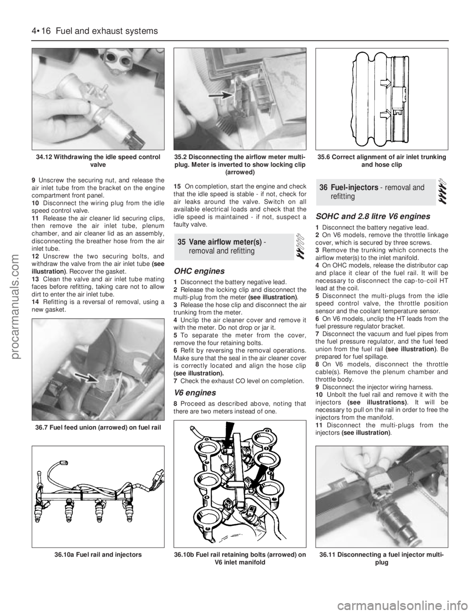
withdraw the valve from the air inlet tube (see
illustration). Recover the gasket.
13Clean the valve and air inlet tube mating
faces before refitting, taking care not to allow
dirt to enter the air inlet tube.
14Refitting is a reversal of removal, using a
new gasket.15On completion, start the engine and check
that the idle speed is stable - if not, check for
air leaks around the valve. Switch on all
available electrical loads and check that the
idle speed is maintained - if not, suspect a
faulty valve.
OHC engines
1Disconnect the battery negative lead.
2Release the locking clip and disconnect the
multi-plug from the meter (see illustration).
3Release the hose clip and disconnect the air
trunking from the meter.
4Unclip the air cleaner cover and remove it
with the meter. Do not drop or jar it.
5To separate the meter from the cover,
remove the four retaining bolts.
6Refit by reversing the removal operations.
Make sure that the seal in the air cleaner cover
is correctly located and align the hose clip
(seeillustration).
7Check the exhaust CO level on completion.
V6 engines
8Proceed as described above, noting that
there are two meters instead of one.
SOHC and 2.8 litre V6 engines
1Disconnect the battery negative lead.
2On V6 models, remove the throttle linkage
cover, which is secured by three screws.
3Remove the trunking which connects the
airflow meter(s) to the inlet manifold.
4On OHCmodels, release the distributor cap
and place it clear of the fuel rail. It will be
necessary to disconnect the cap-to-coil HT
lead at the coil.
5Disconnect the multi-plugs from the idle
speed control valve, the throttle position
sensor and the coolant temperature sensor.
6On V6 models, unclip the HT leads from the
fuel pressure regulator bracket.
7Disconnect the vacuum and fuel pipes from
the fuel pressure regulator, and the fuel feed
union from the fuel rail (see illustration). Be
prepared for fuel spillage.
8On V6 models, disconnect the throttle
cable(s). Remove the plenum chamber and
throttle body.
9Disconnect the injector wiring harness.
10Unbolt the fuel rail and remove it with the
injectors (see illustrations). It will be
necessary to pull on the rail in order to free the
injectors from the manifold.
11Disconnect the multi-plugs from the
injectors (see illustration).
36Fuel-injectors - removal and
refitting
35Vane airflow meter(s) -
removal and refitting
4•16Fuel and exhaust systems
34.12 Withdrawing the idle speed control
valve
36.7 Fuel feed union (arrowed) on fuel rail
36.10a Fuel rail and injectors36.10b Fuel rail retaining bolts (arrowed) on
V6 inlet manifold36.11 Disconnecting a fuel injector multi-
plug
35.2 Disconnecting the airflow meter multi-
plug. Meter is inverted to show locking clip
(arrowed)35.6 Correct alignment of air inlet trunking
and hose clip
procarmanuals.com
Page 110 of 255
12Extract the retaining clips and pull the
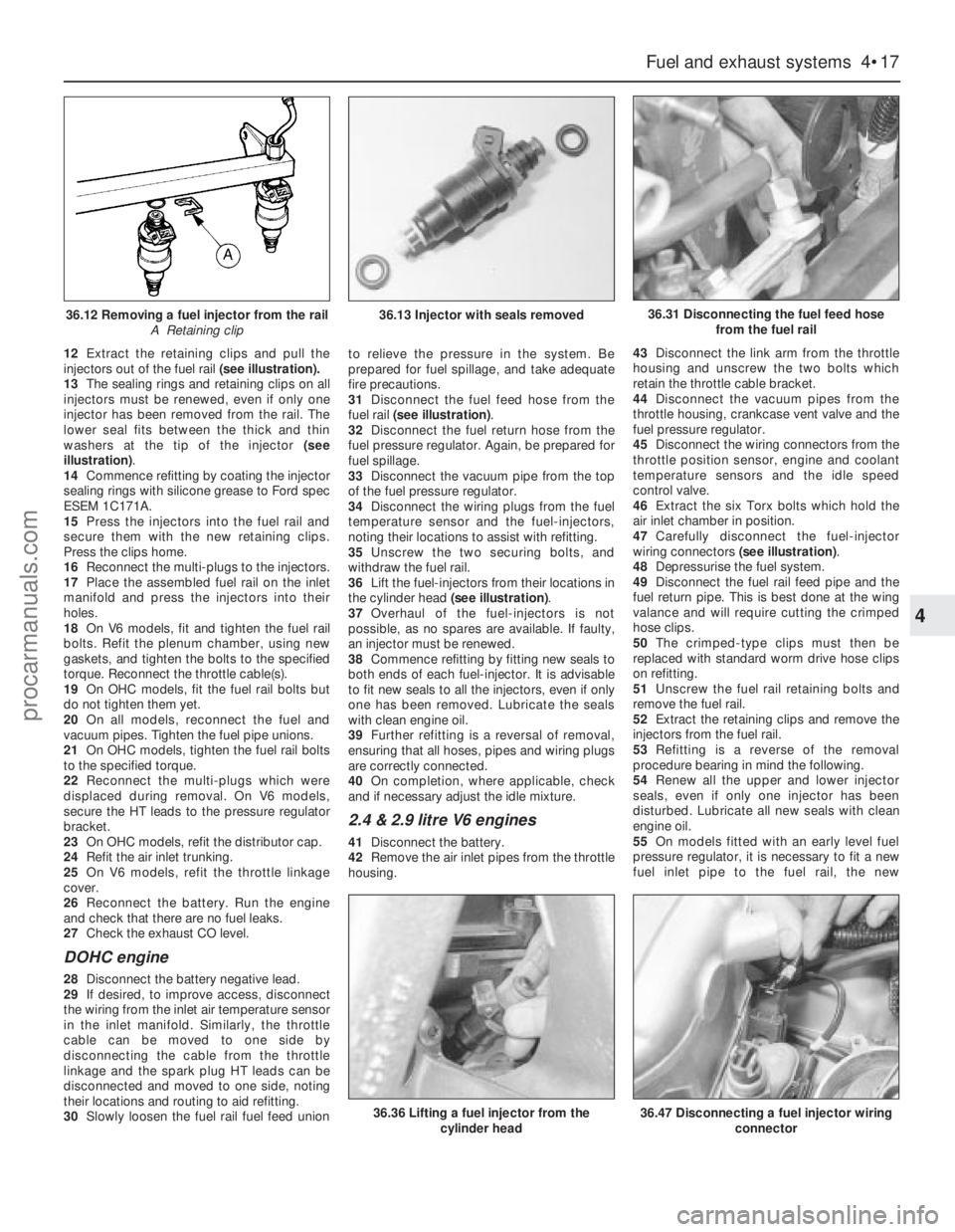
injectors out of the fuel rail(see illustration).
13The sealing rings and retaining clips on all
injectors must be renewed, even if only one
injector has been removed from the rail. The
lower seal fits between the thick and thin
washers at the tip of the injector (see
illustration).
14Commence refitting by coating the injector
sealing rings with silicone grease to Ford spec
ESEM 1C171A.
15Press the injectors into the fuel rail and
secure them with the new retaining clips.
Press the clips home.
16Reconnect the multi-plugs to the injectors.
17Place the assembled fuel rail on the inlet
manifold and press the injectors into their
holes.
18On V6 models, fit and tighten the fuel rail
bolts. Refit the plenum chamber, using new
gaskets, and tighten the bolts to the specified
torque. Reconnect the throttle cable(s).
19On OHCmodels, fit the fuel rail bolts but
do not tighten them yet.
20On all models, reconnect the fuel and
vacuum pipes. Tighten the fuel pipe unions.
21On OHCmodels, tighten the fuel rail bolts
to the specified torque.
22Reconnect the multi-plugs which were
displaced during removal. On V6 models,
secure the HT leads to the pressure regulator
bracket.
23On OHCmodels, refit the distributor cap.
24Refit the air inlet trunking.
25On V6 models, refit the throttle linkage
cover.
26Reconnect the battery. Run the engine
and check that there are no fuel leaks.
27Check the exhaust CO level.
DOHC engine
28Disconnect the battery negative lead.
29If desired, to improve access, disconnect
the wiring from the inlet air temperature sensor
in the inlet manifold. Similarly, the throttle
cable can be moved to one side by
disconnecting the cable from the throttle
linkage and the spark plug HT leads can be
disconnected and moved to one side, noting
their locations and routing to aid refitting.
30Slowly loosen the fuel rail fuel feed unionto relieve the pressure in the system. Be
prepared for fuel spillage, and take adequate
fire precautions.
31Disconnect the fuel feed hose from the
fuel rail (see illustration).
32Disconnect the fuel return hose from the
fuel pressure regulator. Again, be prepared for
fuel spillage.
33Disconnect the vacuum pipe from the top
of the fuel pressure regulator.
34Disconnect the wiring plugs from the fuel
temperature sensor and the fuel-injectors,
noting their locations to assist with refitting.
35Unscrew the two securing bolts, and
withdraw the fuel rail.
36Lift the fuel-injectors from their locations in
the cylinder head (see illustration).
37Overhaul of the fuel-injectors is not
possible, as no spares are available. If faulty,
an injector must be renewed.
38Commence refitting by fitting new seals to
both ends of each fuel-injector. It is advisable
to fit new seals to all the injectors, even if only
one has been removed. Lubricate the seals
with clean engine oil.
39Further refitting is a reversal of removal,
ensuring that all hoses, pipes and wiring plugs
are correctly connected.
40On completion, where applicable, check
and if necessary adjust the idle mixture.
2.4 & 2.9 litre V6 engines
41Disconnect the battery.
42Remove the air inlet pipes from the throttle
housing.43Disconnect the link arm from the throttle
housing and unscrew the two bolts which
retain the throttle cable bracket.
44Disconnect the vacuum pipes from the
throttle housing, crankcase vent valve and the
fuel pressure regulator.
45Disconnect the wiring connectors from the
throttle position sensor, engine and coolant
temperature sensors and the idle speed
control valve.
46Extract the six Torx bolts which hold the
air inlet chamber in position.
47Carefully disconnect the fuel-injector
wiring connectors (see illustration).
48Depressurise the fuel system.
49Disconnect the fuel rail feed pipe and the
fuel return pipe. This is best done at the wing
valance and will require cutting the crimped
hose clips.
50The crimped-type clips must then be
replaced with standard worm drive hose clips
on refitting.
51Unscrew the fuel rail retaining bolts and
remove the fuel rail.
52Extract the retaining clips and remove the
injectors from the fuel rail.
53Refitting is a reverse of the removal
procedure bearing in mind the following.
54Renew all the upper and lower injector
seals, even if only one injector has been
disturbed. Lubricate all new seals with clean
engine oil.
55On models fitted with an early level fuel
pressure regulator, it is necessary to fit a new
fuel inlet pipe to the fuel rail, the new
Fuel and exhaust systems 4•17
4
36.12 Removing a fuel injector from the rail
A Retaining clip36.13 Injector with seals removed36.31 Disconnecting the fuel feed hose
from the fuel rail
36.36 Lifting a fuel injector from the
cylinder head36.47 Disconnecting a fuel injector wiring
connector
procarmanuals.com
Page 112 of 255
24Unbolt and remove the regulator from the
fuel rail. Remove the sealing O-ring and
discard it; a new one must be used on
refitting.
25Refitting is a reverse of the removal
procedure applying a smear of clean engine oil
to the new regulator O-ring. On models
equipped with a late level regulator, ensure
that the return pipe is securely held in position
by the retaining collar.
26On completion, switch the ignition on and
off five times without cranking the engine to
pressurise the fuel system.
27With the system pressurised check all
disturbed fuel unions for signs of leakage.
1The potentiometer is located on the right-
hand side of the engine compartment, behind
the MAP sensor.
2Disconnect the battery negative lead.
3Remove the securing screw, then withdraw
the potentiometer and disconnect the wiring
plug.
4Refitting is a reversal of removal. On
completion adjust the idle mixture.1On 2.4 & 2.9 litre V6 engines, disconnect the
battery.
2Disconnect the switch wiring connector.
3Slacken and remove the switch from the
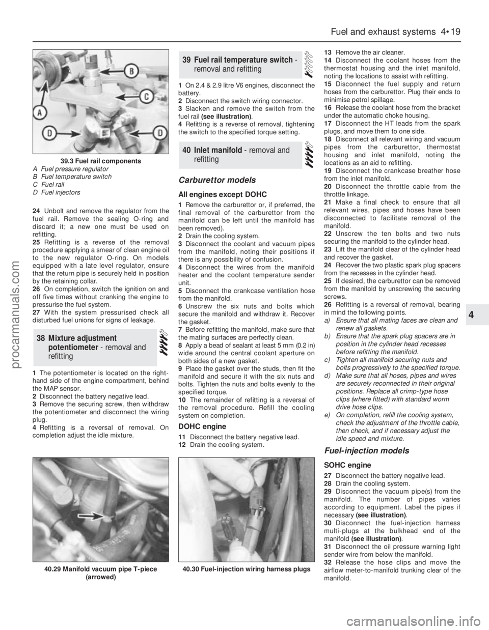
fuel rail (see illustration).
4Refitting is a reverse of removal, tightening
the switch to the specified torque setting.
Carburettor models
All engines except DOHC
1Remove the carburettor or, if preferred, the
final removal of the carburettor from the
manifold can be left until the manifold has
been removed).
2Drain the cooling system.
3Disconnect the coolant and vacuum pipes
from the manifold, noting their positions if
there is any possibility of confusion.
4Disconnect the wires from the manifold
heater and the coolant temperature sender
unit.
5Disconnect the crankcase ventilation hose
from the manifold.
6Unscrew the six nuts and bolts which
secure the manifold and withdraw it. Recover
the gasket.
7Before refitting the manifold, make sure that
the mating surfaces are perfectly clean.
8Apply a bead of sealant at least 5 mm (0.2 in)
wide around the central coolant aperture on
both sides of a new gasket.
9Place the gasket over the studs, then fit the
manifold and secure it with the six nuts and
bolts. Tighten the nuts and bolts evenly to the
specified torque.
10The remainder of refitting is a reversal of
the removal procedure. Refill the cooling
system on completion.
DOHC engine
11Disconnect the battery negative lead.
12Drain the cooling system.13Remove the air cleaner.
14Disconnect the coolant hoses from the
thermostat housing and the inlet manifold,
noting the locations to assist with refitting.
15Disconnect the fuel supply and return
hoses from the carburettor. Plug their ends to
minimise petrol spillage.
16Release the coolant hose from the bracket
under the automatic choke housing.
17Disconnect the HT leads from the spark
plugs, and move them to one side.
18Disconnect all relevant wiring and vacuum
pipes from the carburettor, thermostat
housing and inlet manifold, noting the
locations as an aid to refitting.
19Disconnect the crankcase breather hose
from the inlet manifold.
20Disconnect the throttle cable from the
throttle linkage.
21Make a final check to ensure that all
relevant wires, pipes and hoses have been
disconnected to facilitate removal of the
manifold.
22Unscrew the ten bolts and two nuts
securing the manifold to the cylinder head.
23Lift the manifold clear of the cylinder head
and recover the gasket.
24Recover the two plastic spark plug spacers
from the recesses in the cylinder head.
25If desired, the carburettor can be removed
from the manifold by unscrewing the securing
screws.
26Refitting is a reversal of removal, bearing
in mind the following points.
a)Ensure that all mating faces are clean and
renew all gaskets.
b)Ensure that the spark plug spacers are in
position in the cylinder head recesses
before refitting the manifold.
c)Tighten all manifold securing nuts and
bolts progressively to the specified torque.
d)Make sure that all hoses, pipes and wires
are securely reconnected in their original
positions. Replace all crimp-type hose
clips (where fitted) with standard worm
drive hose clips.
e)On completion, refill the cooling system,
check the adjustment of the throttle cable,
then check, and if necessary adjust the
idle speed and mixture.
Fuel-injection models
SOHC engine
27Disconnect the battery negative lead.
28Drain the cooling system.
29Disconnect the vacuum pipe(s) from the
manifold. The number of pipes varies
according to equipment. Label the pipes if
necessary (see illustration).
30Disconnect the fuel-injection harness
multi-plugs at the bulkhead end of the
manifold (see illustration).
31Disconnect the oil pressure warning light
sender wire from below the manifold.
32Release the hose clips and move the
airflow meter-to-manifold trunking clear of the
manifold.
40Inlet manifold - removal and
refitting
39Fuel rail temperature switch -
removal and refitting
38Mixture adjustment
potentiometer - removal and
refitting
Fuel and exhaust systems 4•19
4
39.3 Fuel rail components
A Fuel pressure regulator
B Fuel temperature switch
C Fuel rail
D Fuel injectors
40.29 Manifold vacuum pipe T-piece
(arrowed)40.30 Fuel-injection wiring harness plugs
procarmanuals.com
Page 114 of 255
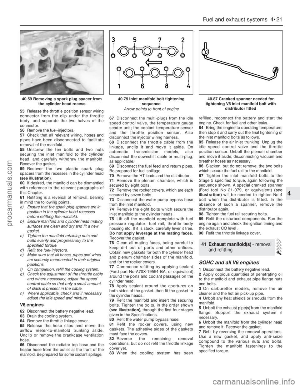
55Release the throttle position sensor wiring
connector from the clip under the throttle
body, and separate the two halves of the
connector.
56Remove the fuel-injectors.
57Check that all relevant wiring, hoses and
pipes have been disconnected to facilitate
removal of the manifold.
58Unscrew the ten bolts and two nuts
securing the inlet manifold to the cylinder
head, and carefully withdraw the manifold.
Recover the gasket.
59Recover the two plastic spark plug
spacers from the recesses in the cylinder head
(see illustration).
60If desired, the manifold can be dismantled
with reference to the relevant paragraphs of
this Chapter.
61Refitting is a reversal of removal, bearing
in mind the following points.
a)Ensure that the spark plug spacers are in
position in the cylinder head recesses
before refitting the manifold.
b)Ensure manifold and cylinder head mating
surfaces are clean and dry and fit a new
gasket.
c)Tighten the manifold retaining nuts and
bolts evenly and progressively to the
specified torque.
d)Refit the fuel-injectors.
e)Make sure that all hoses, pipes and wires
are securely reconnected in their original
positions.
f)On completion, refill the cooling system.
g)Check the adjustment of the throttle cable
and where necessary, adjust the speed
control cable so that only a small amount
of slack is present in the cable.
h)Where applicable, check and if necessary
adjust the idle speed and mixture.
V6 engines
62Disconnect the battery negative lead.
63Drain the cooling system.
64Remove the throttle linkage cover.
65Release the hose clips and move the
airflow meter-to-manifold trunking aside.
Unclip or remove the crankcase ventilation
hose.
66Disconnect the radiator top hose and the
heater hose from the outlet at the front of the
manifold. Be prepared for some coolant spillage.67Disconnect the multi-plugs from the idle
speed control valve, the temperature gauge
sender unit; the coolant temperature sensor
and the throttle position sensor. Also
disconnect the injector wiring harness.
68Disconnect the throttle cable from the
linkage, unclip it and move it aside. On
automatic transmission models, also
disconnect the downshift cable or multi-plug,
as applicable.
69Disconnect the fuel feed and return pipes.
Be prepared for fuel spillage.
70Remove the HT leads and the distributor.
71Remove the plenum chamber, which is
secured by eight bolts.
72Remove the rocker covers, which are each
secured by seven bolts.
73Disconnect the water pump bypass hose
from the inlet manifold.
74Remove the eight bolts which secure the
inlet manifold to the cylinder heads.
75Lift off the manifold complete with fuel
pressure regulator, fuel rail, throttle body
housing etc. If it is stuck, carefully lever it free.
Do not apply leverage at the mating faces.
Recover the gasket.
76Clean all mating faces, being careful to
keep dirt out of ports and other orifices.
Obtain new gaskets for both the cylinder head
and plenum chamber sides of the manifold,
and for the rocker covers.
77Commence refitting by applying sealant
(Ford part No A70X-19554-BA, or equivalent)
around the ports and coolant passages on the
cylinder head.
78Apply sealant around the apertures on
both sides of the gasket. then fit the gasket to
the cylinder heads.
79Refit the manifold and insert the securing
bolts. Tighten the bolts, in the order shown
(see illustration),through the first four stages
given in the Specifications.
80Refit the water pump bypass hose.
81Refit the rocker covers, using new
gaskets. The adhesive sides of the gaskets
must face the covers.
82Reverse the remaining removal
operations, but do not refit the throttle linkage
cover yet.
83When the cooling system has beenrefilled, reconnect the battery and start the
engine. Check for fuel and other leaks.
84Bring the engine to operating temperature,
then stop it and carry out the final tightening of
the inlet manifold bolts as follows.
85Release the air inlet trunking. Unplug the
idle speed control valve and the throttle
position sensor. Unbolt the plenum chamber
and move it aside, disconnecting vacuum and
breather hoses as necessary.
86Slacken, but do not remove, the two bolts
which secure the fuel rail to the manifold.
87Tighten the inlet manifold bolts to the
Stage 5 specified torque, again following the
sequence shown. A special cranked spanner
(Ford tool No 21-079, or equivalent)(see
illustration)will be needed to tighten No 4
bolt when the distributor is fitted. In the
absence of such a spanner, remove the
distributor again.
88Tighten the fuel rail securing bolts.
89Refit the disturbed components. Run the
engine again and check the ignition timing and
the exhaust CO level .
90Refit the throttle linkage cover.
SOHC and all V6 engines
1Disconnect the battery negative lead.
2Apply copious quantities of penetrating oil
to the manifold and exhaust pipe flange nuts
and bolts.
3On carburettor models, remove the air
cleaner and the hot air pick-up pipe.
4Unbolt any heat shields or shrouds from the
manifold.
5Unbolt the exhaust pipe(s) from the manifold
flange. Support the exhaust system if
necessary.
6Unbolt the manifold from the cylinder head
and remove it. Recover the gasket.
7Refit by reversing the removal operations.
Use a new gasket, and apply anti-seize
compound to the various nuts and bolts.
Tighten the manifold fastenings to the
specified torque.
41Exhaust manifold(s) - removal
and refitting
Fuel and exhaust systems 4•21
4
40.59 Removing a spark plug spacer from
the cylinder head recess40.79 Inlet manifold bolt tightening
sequence
Arrow points to front of engine40.87 Cranked spanner needed for
tightening V6 inlet manifold bolt with
distributor fitted
procarmanuals.com
Page 119 of 255
The ignition system is responsible for
igniting the fuel/air charge in each cylinder at
the correct moment. The components of the
system are the spark plugs, ignition coil,
distributor and connecting leads. Overall
control of the system is one of the functions of
the engine management module. Fuel-
injection models have a subsidiary ignition
module mounted on the distributor.
There are no contact breaker points in the
distributor. A square wave signal is generated
by the distributor electro-magnetically; this
signal is used by the engine management
module as a basis for switching the coil LT
current. Speed-related (centrifugal) advance is
also handled by the module. On carburettor
models, ignition timing is also advanced under
conditions of high inlet manifold vacuum.The engine management models are “black
boxes” which regulate both the fuel and the
ignition systems to obtain the best power,
economy and emission levels. The module
fitted to carburettor models is known as the
ESC II (Electronic Spark Control Mk II) module.
On fuel-injection models the more powerful
EEC IV (Electronic Engine Control Mk IV)
module is used.
Both types of module receive inputs from
sensors monitoring coolant temperature,
distributor rotor position and (on some
models) manifold vacuum. Outputs from the
module control ignition timing, inlet manifold
heating and (except on 1.8 litre models) idle
speed. The EEC IV module also has overall
control of the fuel-injection system, from
which it receives information.
Provision is made for the ignition timing to
be retarded to allow the use of low octane fuel
if necessary. On all except 1.8 litre models
there is also a facility for raising the idle speed.The EEC IV module contains self-test
circuitry which enables a technician with the
appropriate test equipment to diagnose faults
in a very short time. A Limited Operation
Strategy (LOS) means that the car is still
driveable, albeit at reduced power and
efficiency, in the event of a failure in the
module or its sensors.
Due to the complexity and expense of the
test equipment dedicated to the engine
management system, suspected faults should
be investigated by a Ford dealer, or other
competent specialist. This Chapter deals with
component removal and refitting, and with
some simple checks and adjustments.
On DOHC carburettor engines, the basic
operating principles of the ignition system are
as described above. A development of the
ESC II (Electronic Spark Control ll) system is
used to control the operation of the engine.
The ESC II module receives information from a
crankshaft speed/position sensor and an
1General information and
precautions
5•2Engine electrical systems
Ignition coil
Make . . . . . . . . . . . . . . . . . . . . . . . . . . . . . . . . . . . . . . . . . . . . . . . . . . . .Bosch, Femsa or Polmot
Primary resistance . . . . . . . . . . . . . . . . . . . . . . . . . . . . . . . . . . . . . . . . .0.72 to 0.86 ohm
Secondary resistance:
All except DOHC fuel-injection . . . . . . . . . . . . . . . . . . . . . . . . . . . . . .4.5 to 7.0 k ohms
DOHC fuel-injection . . . . . . . . . . . . . . . . . . . . . . . . . . . . . . . . . . . . . .4.5 to 8.6 k ohms
Output voltage (open-circuit):
All except DOHC fuel-injection . . . . . . . . . . . . . . . . . . . . . . . . . . . . . .25 kV minimum
DOHC fuel-injection . . . . . . . . . . . . . . . . . . . . . . . . . . . . . . . . . . . . . .30 kV minimum
HT leads
Maximum resistance per lead . . . . . . . . . . . . . . . . . . . . . . . . . . . . . . . . .30 k ohms
Distributor
Make . . . . . . . . . . . . . . . . . . . . . . . . . . . . . . . . . . . . . . . . . . . . . . . . . . . .Bosch or Motorcraft
Rotation . . . . . . . . . . . . . . . . . . . . . . . . . . . . . . . . . . . . . . . . . . . . . . . . .Clockwise (viewed from above)
Automatic advance . . . . . . . . . . . . . . . . . . . . . . . . . . . . . . . . . . . . . . . . .Controlled by module
Dwell angle . . . . . . . . . . . . . . . . . . . . . . . . . . . . . . . . . . . . . . . . . . . . . . .Controlled by module
Ignition timing (see text)
SOHC and 2.8 litre V6 engines:
Leaded fuel (97 octane):
Carburettor models . . . . . . . . . . . . . . . . . . . . . . . . . . . . . . . . . . . . .10°BTDC
Fuel-injection models . . . . . . . . . . . . . . . . . . . . . . . . . . . . . . . . . . .12°BTDC
Unleaded fuel (95 octane):
Carburettor models . . . . . . . . . . . . . . . . . . . . . . . . . . . . . . . . . . . . .6°BTDC
Fuel-injection models:
2.0 litre . . . . . . . . . . . . . . . . . . . . . . . . . . . . . . . . . . . . . . . . . . . . .8°BTDC
2.8 litre . . . . . . . . . . . . . . . . . . . . . . . . . . . . . . . . . . . . . . . . . . . . .12°BTDC (no change)
2.4 & 2.9 litre V6 engines:
Models with catalytic converter . . . . . . . . . . . . . . . . . . . . . . . . . . . . .15°BTDC
Models without catalytic converter . . . . . . . . . . . . . . . . . . . . . . . . . . .12°BTDC*
* Standard setting for 97 octane leaded fuel.
Torque wrench settingsNmlbf ft
Alternator adjusting strap:
To steering pump bracket (OHC) . . . . . . . . . . . . . . . . . . . . . . . . . . . .21 to 2616 to 19
To front cover (V6) . . . . . . . . . . . . . . . . . . . . . . . . . . . . . . . . . . . . . . . .41 to 5130 to 38
Spark plugs:
All models except 2.8 litre V6 . . . . . . . . . . . . . . . . . . . . . . . . . . . . . . .20 to 2815 to 21
2.8 litre V6 . . . . . . . . . . . . . . . . . . . . . . . . . . . . . . . . . . . . . . . . . . . . . .30 to 4022 to 30
Air charge temperature sensor . . . . . . . . . . . . . . . . . . . . . . . . . . . . . . . .20 to 2515 to 18
Engine coolant temperature sensor . . . . . . . . . . . . . . . . . . . . . . . . . . . .20 to 2515 to 18
Fuel rail temperature sensor (DOHC) . . . . . . . . . . . . . . . . . . . . . . . . . . .8 to 116 to 8
Crankshaft speed/position sensor screw (DOHC) . . . . . . . . . . . . . . . . .3 to 52 to 4
procarmanuals.com
Page 127 of 255
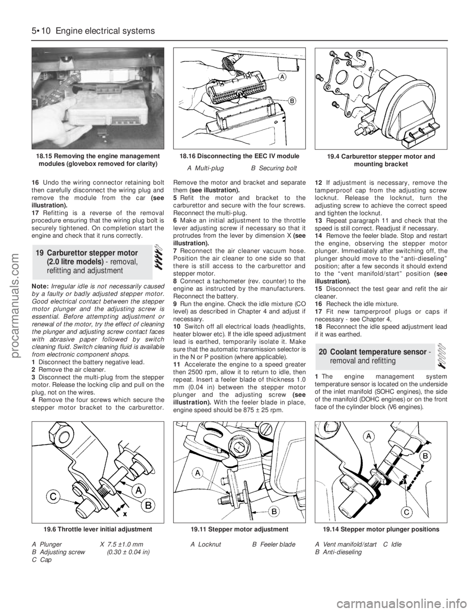
16Undo the wiring connector retaining bolt
then carefully disconnect the wiring plug and
remove the module from the car (see
illustration).
17Refitting is a reverse of the removal
procedure ensuring that the wiring plug bolt is
securely tightened. On completion start the
engine and check that it runs correctly.
Note: Irregular idle is not necessarily caused
by a faulty or badly adjusted stepper motor.
Good electrical contact between the stepper
motor plunger and the adjusting screw is
essential. Before attempting adjustment or
renewal of the motor, try the effect of cleaning
the plunger and adjusting screw contact faces
with abrasive paper followed by switch
cleaning fluid. Switch cleaning fluid is available
from electronic component shops.
1Disconnect the battery negative lead.
2Remove the air cleaner.
3Disconnect the multi-plug from the stepper
motor. Release the locking clip and pull on the
plug, not on the wires.
4Remove the four screws which secure the
stepper motor bracket to the carburettor.Remove the motor and bracket and separate
them (see illustration).
5Refit the motor and bracket to the
carburettor and secure with the four screws.
Reconnect the multi-plug.
6Make an initial adjustment to the throttle
lever adjusting screw if necessary so that it
protrudes from the lever by dimension X (see
illustration).
7Reconnect the air cleaner vacuum hose.
Position the air cleaner to one side so that
there is still access to the carburettor and
stepper motor.
8Connect a tachometer (rev. counter) to the
engine as instructed by the manufacturers.
Reconnect the battery.
9Run the engine. Check the idle mixture (CO
level) as described in Chapter 4 and adjust if
necessary.
10Switch off all electrical loads (headlights,
heater blower etc). If the idle speed adjustment
lead is earthed, temporarily isolate it. Make
sure that the automatic transmission selector is
in the N or P position (where applicable).
11Accelerate the engine to a speed greater
then 2500 rpm, allow it to return to idle, then
repeat. Insert a feeler blade of thickness 1.0
mm (0.04 in) between the stepper motor
plunger and the adjusting screw(see
illustration).With the feeler blade in place,
engine speed should be 875 ±25 rpm. 12If adjustment is necessary, remove the
tamperproof cap from the adjusting screw
locknut. Release the locknut, turn the
adjusting screw to achieve the correct speed
and tighten the locknut.
13Repeat paragraph 11 and check that the
speed is still correct. Readjust if necessary.
14Remove the feeler blade. Stop and restart
the engine, observing the stepper motor
plunger. Immediately after switching off, the
plunger should move to the “anti-dieseling”
position; after a few seconds it should extend
to the “vent manifold/start” position (see
illustration).
15Disconnect the test gear and refit the air
cleaner.
16Recheck the idle mixture.
17Fit new tamperproof plugs or caps if
necessary - see Chapter 4,
18Reconnect the idle speed adjustment lead
if it was earthed.
1The engine management system
temperature sensor is located on the underside
of the inlet manifold (SOHC engines), the side
of the manifold (DOHC engines) or on the front
face of the cylinder block (V6 engines).
20Coolant temperature sensor -
removal and refitting
19Carburettor stepper motor
(2.0 litre models) - removal,
refitting and adjustment
5•10Engine electrical systems
18.16 Disconnecting the EEC IV module
A Multi-plugB Securing bolt
19.6 Throttle lever initial adjustment
A Plunger
B Adjusting screw
C CapX 7.5 ±1.0 mm
(0.30 ±0.04 in)
19.11 Stepper motor adjustment
A LocknutB Feeler blade
19.14 Stepper motor plunger positions
A Vent manifold/start
B Anti-dieselingC Idle
19.4 Carburettor stepper motor and
mounting bracket18.15 Removing the engine management
modules (glovebox removed for clarity)
procarmanuals.com
Page 195 of 255
Computer module and bulb
Models before April 1992
2Remove the instrument panel surround,
which is secured by four screws.
3Carefully pull the module from its location.
Release the multi-plug by pressing
downwards and disconnect it.
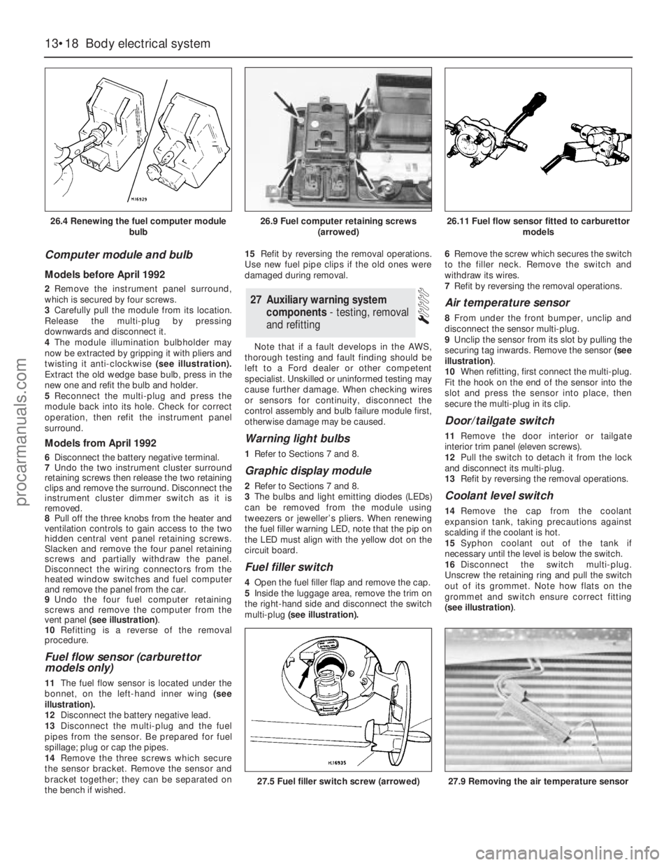
4The module illumination bulbholder may
now be extracted by gripping it with pliers and
twisting it anti-clockwise (see illustration).
Extract the old wedge base bulb, press in the
new one and refit the bulb and holder.
5Reconnect the multi-plug and press the
module back into its hole. Check for correct
operation, then refit the instrument panel
surround.
Models from April 1992
6Disconnect the battery negative terminal.
7Undo the two instrument cluster surround
retaining screws then release the two retaining
clips and remove the surround. Disconnect the
instrument cluster dimmer switch as it is
removed.
8Pull off the three knobs from the heater and
ventilation controls to gain access to the two
hidden central vent panel retaining screws.
Slacken and remove the four panel retaining
screws and partially withdraw the panel.
Disconnect the wiring connectors from the
heated window switches and fuel computer
and remove the panel from the car.
9Undo the four fuel computer retaining
screws and remove the computer from the
vent panel (see illustration).
10Refitting is a reverse of the removal
procedure.
Fuel flow sensor (carburettor
models only)
11The fuel flow sensor is located under the
bonnet, on the left-hand inner wing (see
illustration).
12Disconnect the battery negative lead.
13Disconnect the multi-plug and the fuel
pipes from the sensor. Be prepared for fuel
spillage; plug or cap the pipes.
14Remove the three screws which secure
the sensor bracket. Remove the sensor and
bracket together; they can be separated on
the bench if wished.15Refit by reversing the removal operations.
Use new fuel pipe clips if the old ones were
damaged during removal.
Note that if a fault develops in the AWS,
thorough testing and fault finding should be
left to a Ford dealer or other competent
specialist. Unskilled or uninformed testing may
cause further damage. When checking wires
or sensors for continuity, disconnect the
control assembly and bulb failure module first,
otherwise damage may be caused.
Warning light bulbs
1Refer to Sections 7 and 8.
Graphic display module
2Refer to Sections 7 and 8.
3The bulbs and light emitting diodes (LEDs)
can be removed from the module using
tweezers or jeweller’s pliers. When renewing
the fuel filler warning LED, note that the pip on
the LED must align with the yellow dot on the
circuit board.
Fuel filler switch
4Open the fuel filler flap and remove the cap.
5Inside the luggage area, remove the trim on
the right-hand side and disconnect the switch
multi-plug(see illustration).6Remove the screw which secures the switch
to the filler neck. Remove the switch and
withdraw its wires.
7Refit by reversing the removal operations.
Air temperature sensor
8From under the front bumper, unclip and
disconnect the sensor multi-plug.
9Unclip the sensor from its slot by pulling the
securing tag inwards. Remove the sensor (see
illustration).
10When refitting, first connect the multi-plug.
Fit the hook on the end of the sensor into the
slot and press the sensor into place, then
secure the multi-plug in its clip.
Door/tailgate switch
11Remove the door interior ortailgate
interior trim panel (eleven screws).
12Pull the switch to detach it from the lock
and disconnect its multi-plug.
13Refit by reversing the removal operations.
Coolant level switch
14Remove the cap from the coolant
expansion tank, taking precautions against
scalding if the coolant is hot.
15Syphon coolant out of the tank if
necessary until the level is below the switch.
16Disconnect the switch multi-plug.
Unscrew the retaining ring and pull the switch
out of its grommet. Note how flats on the
grommet and switch ensure correct fitting
(see illustration).
27Auxiliary warning system
components - testing, removal
and refitting
13•18Body electrical system
26.4 Renewing the fuel computer module
bulb
27.5 Fuel filler switch screw (arrowed)27.9 Removing the air temperature sensor
26.9 Fuel computer retaining screws
(arrowed)26.11 Fuel flow sensor fitted to carburettor
models
procarmanuals.com