1985 FORD GRANADA weight
[x] Cancel search: weightPage 61 of 255
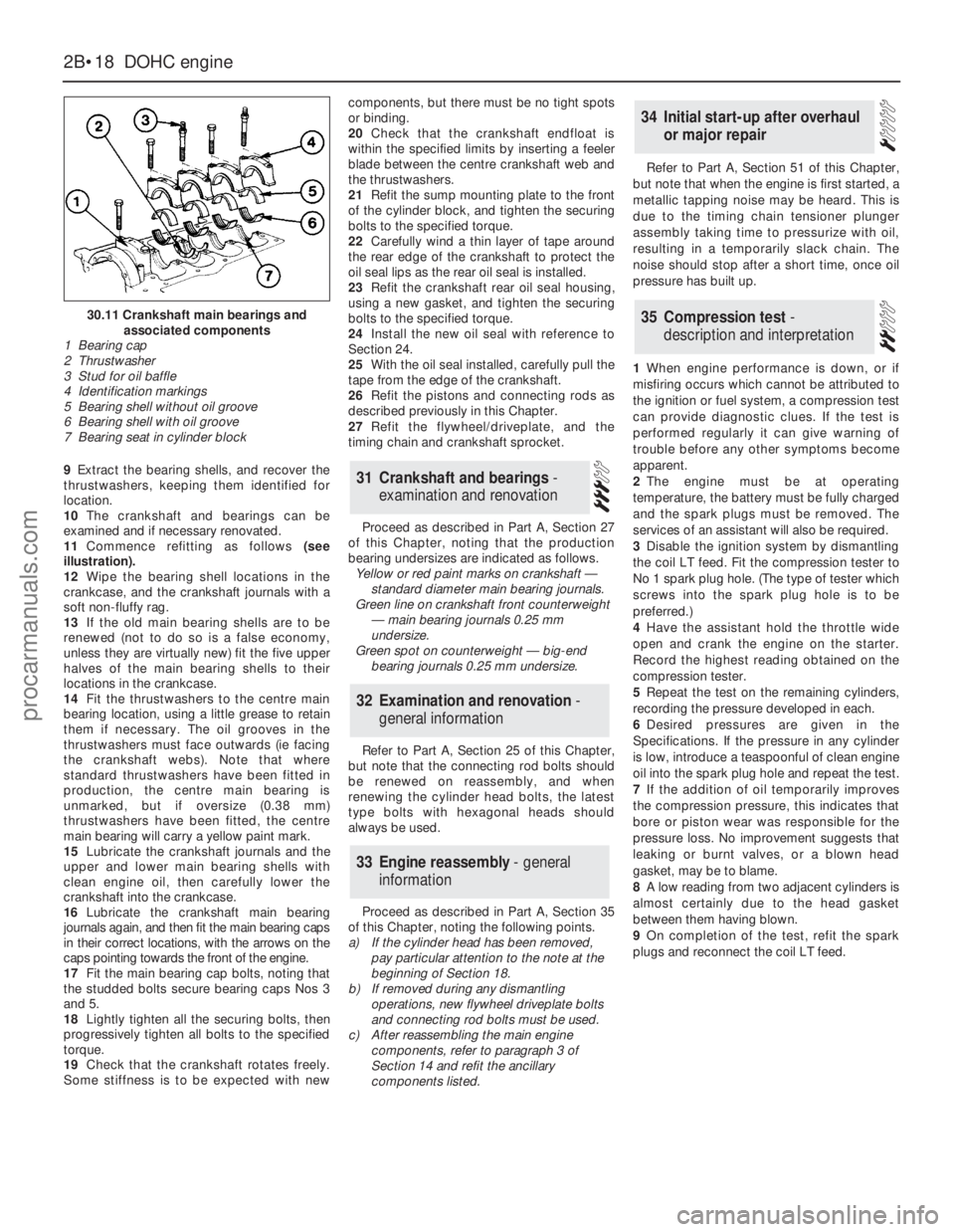
9Extract the bearing shells, and recover the
thrustwashers, keeping them identified for
location.
10The crankshaft and bearings can be
examined and if necessary renovated.
11Commence refitting as follows(see
illustration).
12Wipe the bearing shell locations in the
crankcase, and the crankshaft journals with a
soft non-fluffy rag.
13If the old main bearing shells are to be
renewed (not to do so is a false economy,
unless they are virtually new) fit the five upper
halves of the main bearing shells to their
locations in the crankcase.
14Fit the thrustwashers to the centre main
bearing location, using a little grease to retain
them if necessary. The oil grooves in the
thrustwashers must face outwards (ie facing
the crankshaft webs). Note that where
standard thrustwashers have been fitted in
production, the centre main bearing is
unmarked, but if oversize (0.38 mm)
thrustwashers have been fitted, the centre
main bearing will carry a yellow paint mark.
15Lubricate the crankshaft journals and the
upper and lower main bearing shells with
clean engine oil, then carefully lower the
crankshaft into the crankcase.
16Lubricate the crankshaft main bearing
journals again, and then fit the main bearing caps
in their correct locations, with the arrows on the
caps pointing towards the front of the engine.
17Fit the main bearing cap bolts, noting that
the studded bolts secure bearing caps Nos 3
and 5.
18Lightly tighten all the securing bolts, then
progressively tighten all bolts to the specified
torque.
19Check that the crankshaft rotates freely.
Some stiffness is to be expected with newcomponents, but there must be no tight spots
or binding.
20Check that the crankshaft endfloat is
within the specified limits by inserting a feeler
blade between the centre crankshaft web and
the thrustwashers.
21Refit the sump mounting plate to the front
of the cylinder block, and tighten the securing
bolts to the specified torque.
22Carefully wind a thin layer of tape around
the rear edge of the crankshaft to protect the
oil seal lips as the rear oil seal is installed.
23Refit the crankshaft rear oil seal housing,
using a new gasket, and tighten the securing
bolts to the specified torque.
24Install the new oil seal with reference to
Section 24.
25With the oil seal installed, carefully pull the
tape from the edge of the crankshaft.
26Refit the pistons and connecting rods as
described previously in this Chapter.
27Refit the flywheel/driveplate, and the
timing chain and crankshaft sprocket.
Proceed as described in Part A, Section 27
of this Chapter, noting that the production
bearing undersizes are indicated as follows.
Yellow or red paint marks on crankshaft —
standard diameter main bearing journals.
Green line on crankshaft front counterweight
— main bearing journals 0.25 mm
undersize.
Green spot on counterweight — big-end
bearing journals 0.25 mm undersize.
Refer to Part A, Section 25 of this Chapter,
but note that the connecting rod bolts should
be renewed on reassembly, and when
renewing the cylinder head bolts, the latest
type bolts with hexagonal heads should
always be used.
Proceed as described in Part A, Section 35
of this Chapter, noting the following points.
a)If the cylinder head has been removed,
pay particular attention to the note at the
beginning of Section 18.
b)If removed during any dismantling
operations, new flywheel driveplate bolts
and connecting rod bolts must be used.
c)After reassembling the main engine
components, refer to paragraph 3 of
Section 14 and refit the ancillary
components listed.Refer to Part A, Section 51 of this Chapter,
but note that when the engine is first started, a
metallic tapping noise may be heard. This is
due to the timing chain tensioner plunger
assembly taking time to pressurize with oil,
resulting in a temporarily slack chain. The
noise should stop after a short time, once oil
pressure has built up.
1When engine performance is down, or if
misfiring occurs which cannot be attributed to
the ignition or fuel system, a compression test
can provide diagnostic clues. If the test is
performed regularly it can give warning of
trouble before any other symptoms become
apparent.
2The engine must be at operating
temperature, the battery must be fully charged
and the spark plugs must be removed. The
services of an assistant will also be required.
3Disable the ignition system by dismantling
the coil LT feed. Fit the compression tester to
No 1 spark plug hole. (The type of tester which
screws into the spark plug hole is to be
preferred.)
4Have the assistant hold the throttle wide
open and crank the engine on the starter.
Record the highest reading obtained on the
compression tester.
5Repeat the test on the remaining cylinders,
recording the pressure developed in each.
6Desired pressures are given in the
Specifications. If the pressure in any cylinder
is low, introduce a teaspoonful of clean engine
oil into the spark plug hole and repeat the test.
7If the addition of oil temporarily improves
the compression pressure, this indicates that
bore or piston wear was responsible for the
pressure loss. No improvement suggests that
leaking or burnt valves, or a blown head
gasket, may be to blame.
8A low reading from two adjacent cylinders is
almost certainly due to the head gasket
between them having blown.
9On completion of the test, refit the spark
plugs and reconnect the coil LT feed.
35Compression test -
description and interpretation
34Initial start-up after overhaul
or major repair
33Engine reassembly - general
information
32Examination and renovation -
general information
31Crankshaft and bearings -
examination and renovation
2B•18DOHCengine
30.11 Crankshaft main bearings and
associated components
1 Bearing cap
2 Thrustwasher
3 Stud for oil baffle
4 Identification markings
5 Bearing shell without oil groove
6 Bearing shell with oil groove
7 Bearing seat in cylinder block
procarmanuals.com
Page 67 of 255
The V6 engine fitted to the Granada is only
available in fuel-injected form. Mechanically,
the design of the engine is well-established,
and it is improved by the latest fuel, ignition and
engine management systems (see illustration).
The combined crankcase and cylinder block
is made of cast iron, and houses the pistons,
crankshaft and camshaft. The sump is
attached to the bottom of the crankcase and
the cylinder heads to the top.
The cylinder heads are of the crossflow
design, the inlet manifold being located
between them and the exhaust manifolds
being on the outboard sides. The overhead
valves are operated by tappets, pushrods and
rockers from the centrally located camshaft.
Camshaft drive is by gears (2.8 litre) or chain
(2.4 & 2.9 litre).
The crankshaft runs in four main bearings.
Endfloat is controlled by thrust flanges on the
No 3 bearing shells. The connecting rods are
selected so that all are in the same weight class.
Aluminium alloy pistons are used. The
gudgeon pins are an interference fit in their
connecting rods.The lubrication system is of the usual wet
sump, pressure fed type, with a full-flow
disposable canister oil filter. The oil pump is
driven by a shaft which engages in the bottom
of the distributor drivegear.
The following operations can be carried out
without removing the engine, although some
work will be easier and quicker with the engine
removed.
a)Removal and refitting of the cylinder
heads
b)Removal and refitting of the sump and oil
pump
c)Removal and refitting of the timing gears
d)Removal and refitting of the pistons,
connecting rods and big-end bearings
e)Renewal of the engine mountings
f)Removal and refitting of the flywheel
g)Renewal of the crankshaft front and rear
oil seals
h)Removal and refitting of the camshaft
(after removal of the cylinder heads,
tappets and timing gears)The engine must be removed for the
following operations:
a)Renewal of the crankshaft main bearings
b)Removal and refitting of the crankshaft
The engine is removed from above, without
the transmission. Removal with the
transmission is not recommended because of
the weight and unwieldiness of the combined
units.
2.8 litre engine
1Disconnect the battery negative lead.
2Remove the bonnet.
3Remove the throttle valve cover, which is
retained by three screws.
4Remove the air cleaner cover, valve airflow
5Engine - removal
4Methods of engine removal
3Major operations requiring
engine removal
2Major operations possible with
the engine in the vehicle
1General information
2C•6V6 engines
Cylinder head
Identification mark:
BRC engine . . . . . . . . . . . . . . . . . . . . . . . . . . . . . . . . . . . . . . . . . . . . .F
BRD and BRE engines . . . . . . . . . . . . . . . . . . . . . . . . . . . . . . . . . . . .K
Crankshaft
Crankshaft endfloat . . . . . . . . . . . . . . . . . . . . . . . . . . . . . . . . . . . . . . . .0.08 to 0.24 mm
Permitted undersize for main and big-end bearing journals . . . . . . . . . .0.254 mm
Camshaft
Cam lift (inlet and exhaust):
BRC engine . . . . . . . . . . . . . . . . . . . . . . . . . . . . . . . . . . . . . . . . . . . . .6.72mm
BRD and BRE engine . . . . . . . . . . . . . . . . . . . . . . . . . . . . . . . . . . . . .6.54 mm
Cam lobe height (inlet and exhaust):
BRC engine . . . . . . . . . . . . . . . . . . . . . . . . . . . . . . . . . . . . . . . . . . . . .36.08 to 36.25 mm
BRD and BRE engine . . . . . . . . . . . . . . . . . . . . . . . . . . . . . . . . . . . . .36.22 to 36.41 mm
Camshaft endfloat . . . . . . . . . . . . . . . . . . . . . . . . . . . . . . . . . . . . . . . . .0.065 to 0.165 mm
Thrust plate thickness . . . . . . . . . . . . . . . . . . . . . . . . . . . . . . . . . . . . . . .4.02 to 4.05 mm
Valves
Valve timing:
BRC engine . . . . . . . . . . . . . . . . . . . . . . . . . . . . . . . . . . . . . . . . . . . . .As 2.4 litre V6
BRD and BRE engines:
Inlet opens . . . . . . . . . . . . . . . . . . . . . . . . . . . . . . . . . . . . . . . . . . . .30°BTDC
Inlet closes . . . . . . . . . . . . . . . . . . . . . . . . . . . . . . . . . . . . . . . . . . .66°ABDC
Exhaust opens . . . . . . . . . . . . . . . . . . . . . . . . . . . . . . . . . . . . . . . .76°BBDC
Exhaust closes . . . . . . . . . . . . . . . . . . . . . . . . . . . . . . . . . . . . . . . .20°ATDC
Length:
BRC engine:
Inlet . . . . . . . . . . . . . . . . . . . . . . . . . . . . . . . . . . . . . . . . . . . . . . . . .106.2 to 106.9 mm
Exhaust . . . . . . . . . . . . . . . . . . . . . . . . . . . . . . . . . . . . . . . . . . . . . .106.8 to 107.8 mm
BRD and BRE engine:
Inlet . . . . . . . . . . . . . . . . . . . . . . . . . . . . . . . . . . . . . . . . . . . . . . . . .104.7 to 105.4 mm
Exhaust . . . . . . . . . . . . . . . . . . . . . . . . . . . . . . . . . . . . . . . . . . . . . .104.6 to 105.6 mm
Valve spring free length:
BRC engine . . . . . . . . . . . . . . . . . . . . . . . . . . . . . . . . . . . . . . . . . . . . .55.12 mm
BRD and BRE engines . . . . . . . . . . . . . . . . . . . . . . . . . . . . . . . . . . . .53.00 mm
procarmanuals.com
Page 68 of 255
meters and air inlet trunking. Also remove the
oil filler cap, which is connected to the
trunking by a crankcase ventilation hose.
5Release the securing clips and bolts and
remove the upper half of the fan shroud.
6Drain the cooling system and remove the
radiator.
7Disconnect the heater hoses from the
heater matrix and from the coolant outlet.
Unclip the hoses.
8Remove the fan and viscous clutch (where
fitted).
9Disconnect the following wiring:
a)Alternator
b)Temperature gauge sender
c)Engine management temperature sensor
d)Oil pressure switch
e)Idle speed control valve
f)Throttle position sensor
g)Injector nut-harness
h)Distributor multi-plug
i)Distributor-to-coil HT lead
10Disconnect the throttle cable. When
applicable, also disconnect the downshaft
cable or switch.
11Depressurise the fuel system and
disconnect the fuel supply and return lines
(see Chapter 4).
12Remove the steering pump and air
conditioning compressor drivebelts (as
applicable). Unbolt the steering pump and
compressor, move them aside within the limitsof their flexible hoses and support them by
wiring them to adjacent components.
13Remove the distributor cap and rotor.
14Remove the starter motor.
15Drain the engine oil. Unscrew the oil filter
with a strap or chain wrench and remove it; be
prepared for oil spillage.
16On manual gearbox models, disconnect
the clutch cable from the release lever.
17Unbolt the exhaust pipes from the
manifolds.
18On automatic transmission models, unbolt
the torque converter from the driveplate.
19Attach lifting tackle to the engine. If no
lifting eyes are fitted, pass ropes or chains
round the exhaust manifolds.
20Take the weight of the engine, then
remove the single nut on each side which
holds engine bearer to its mountings.
21From under the vehicle unbolt the engine
adapter plate from the bellhousing.
22Remove the engine-to-bellhousing bolts.
Also disconnect or unclip the battery negative
lead, the starter motor lead and the heat
shield.
23Support the transmission, preferably with
a trolley jack.
24Check that nothing has been overlooked,
then raise the engine and draw it forwards
clear of the transmission input shaft. Do not
allow the weight of the engine to hang on the
shaft, and do not lift the transmission by it.25With automatic transmission, make sure
that the torque converter stays engaged with
the oil pump in the transmission as the engine
is withdrawn.
26Lift the engine out of the engine bay and
take it to the bench.
2.4 & 2.9 litre engines
27The removal operations for these engines
are essentially as described for the 2.8 litre
version. Note the following points.
Coolant hoses
28Remove the hoses which run between the
thermostat housing and the water pump, and
the cooling system expansion tank.
29Remove the heater hoses which run
between the thermostat housing or coolant
distribution pipe and oil cooler (where fitted).
Vacuum hoses
30Disconnect the hose from the fuel
pressure regulator.
31Disconnect the hose from the plenum
chamber.
32Disconnect the hose from the throttle valve.
33Disconnect the hose from the T-piece
connector.
V6 engines 2C•7
2C
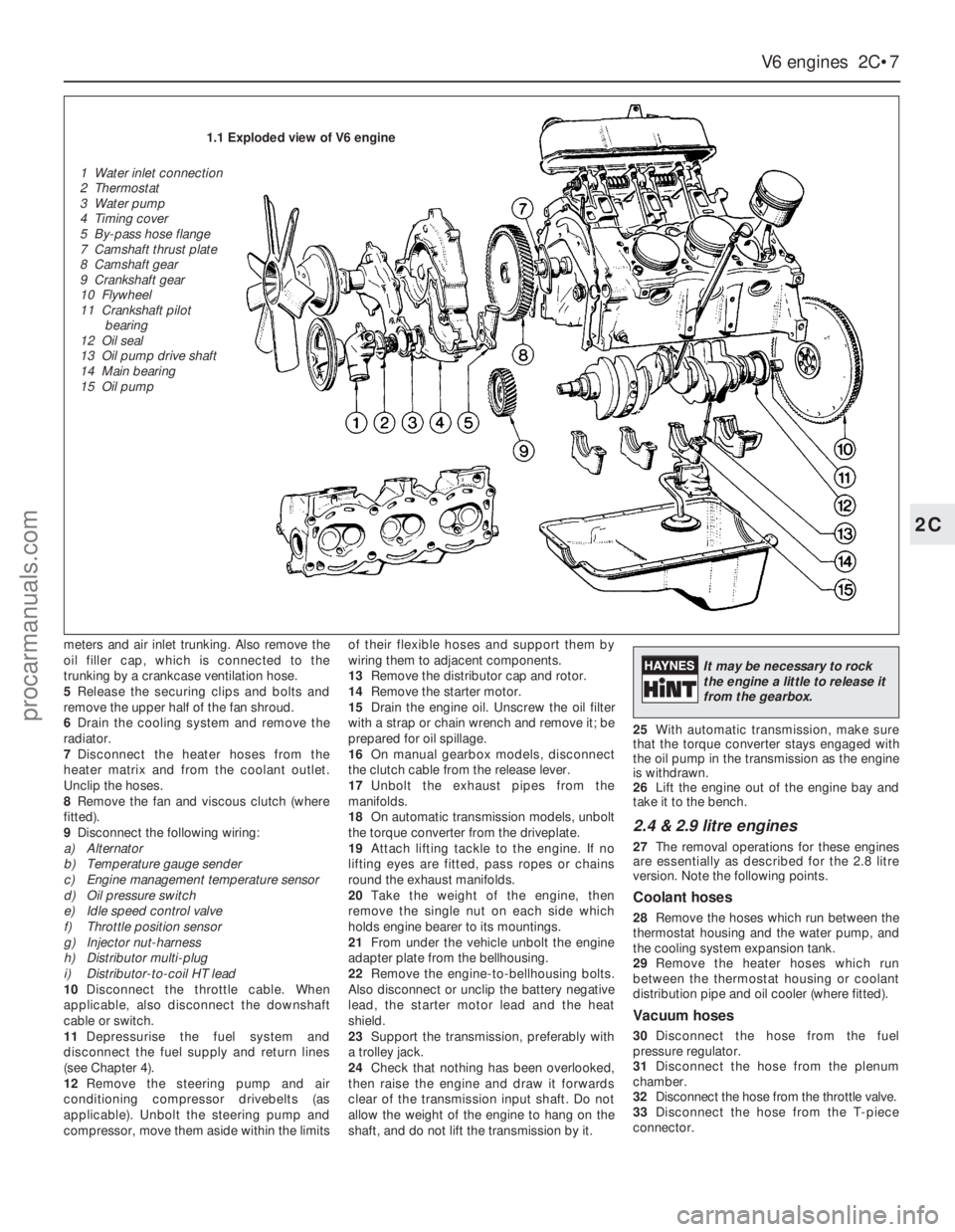
1.1 Exploded view of V6 engine
1 Water inlet connection
2 Thermostat
3 Water pump
4 Timing cover
5 By-pass hose flange
7 Camshaft thrust plate
8 Camshaft gear
9 Crankshaft gear
10 Flywheel
11 Crankshaft pilot
bearing
12 Oil seal
13 Oil pump drive shaft
14 Main bearing
15 Oil pump
It may be necessary to rock
the engine a little to release it
from the gearbox.
procarmanuals.com
Page 71 of 255
4Remove the auxiliary drivebelts.
5Remove the fan and viscous clutch if fitted).
6Jam the crankshaft, either by engaging 5th
gear and applying the handbrake, or by
removing the starter motor and having an
assistant jam a screwdriver in the starter ring
gear teeth. Unbolt the crankshaft pulley. When
the pulley is secured to a vibration damper,
also remove the damper central bolt.
7Remove the pulley or damper, using a puller
if necessary.
8Disconnect the coolant hoses from the front
of the engine, including the water pump
bypass hose.
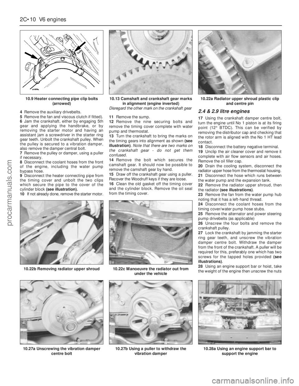
9Disconnect the heater connecting pipe from
the timing cover and unbolt the two clips
which secure the pipe to the cover of the
cylinder block (see illustration).
10If not already done, remove the starter motor.11Remove the sump.
12Remove the nine securing bolts and
remove the timing cover complete with water
pump and thermostat.
13Turn the crankshaft to bring the marks on
the timing gears into alignment as shown (see
illustration). Note that there are two marks on
the crankshaft gear - do not get them
confused.
14Remove the bolt which secures the
camshaft gear. It should now be possible to
remove the camshaft gear by hand.
15Draw off the crankshaft gear using a puller.
Recover the Woodruff keys if they are loose.
16Clean the old gasket off the timing cover
and the cylinder block. Remove the oil seal
from the timing cover.2.4 & 2.9 litre engines
17Using the crankshaft damper centre bolt,
turn the engine until No 1 piston is at its firing
point (12°BTDC). This can be verified by
removing the distributor cap and checking that
the rotor arm is aligned with the No 1 HT lead
contact.
18Disconnect the battery negative terminal.
19Unclip the air cleaner cover and remove it
complete with air flow sensors and air hoses.
Remove the oil filler cap.
20Drain the cooling system, disconnect the
radiator upper hose from the thermostat housing.
21Disconnect the hose which runs between
the water pump and the expansion tank.
22Remove the radiator upper shroud, then
the radiator (see illustrations).
23Remove the fan from the water pump hub
noting that it has a left-hand thread.
24Disconnect the coolant hoses from the
timing cover/water pump hose stubs.
25Remove the alternator and power steering
pump drivebelts (as applicable)
26Unscrew the four bolts and remove the
crankshaft pulley.
27Lock the crankshaft by jamming the starter
ring gear teeth, and unscrew the vibration
damper centre bolt. Withdraw the damper
from the front of the crankshaft. A puller will be
required for this, preferably one which has two
screws for the tapped holes provided (see
illustrations).
28Using an engine support bar or hoist, take
the weight of the engine then unscrew the nuts
2C•10V6 engines
10.9 Heater connecting pipe clip bolts
(arrowed)
10.27a Unscrewing the vibration damper
centre bolt
10.22b Removing radiator upper shroud10.22c Manoeuvre the radiator out from
under the vehicle
10.27b Using a puller to withdraw the
vibration damper10.28a Using an engine support bar to
support the engine
10.13 Camshaft and crankshaft gear marks
in alignment (engine inverted)
Disregard the other mark on the crankshaft gear10.22a Radiator upper shroud plastic clip
and centre pin
procarmanuals.com
Page 97 of 255
The exhaust system fitted in production is
made of aluminised steel, with stainless steel
used in the endplates and baffles of the rear
silencer. Individual sections of the system are
easily renewed in service.
Emission control for the UK market is
achieved largely by the inherent efficiency of
the fuel, ignition and engine management
systems. A welcome spin-off from such
efficiency is remarkably good fuel economy for
a vehicle of such size and weight.
Precautions
Fuel
Many of the procedures in this Chapter
require the removal of fuel lines and
connections which may result in some fuel
spillage. Residual pressure in fuel-injection
systems will remain in the fuel lines long after
the vehicle was last used, therefore extra care
must be taken when disconnecting a fuel line
hose. Loosen any fuel hose slowly to avoid a
sudden release of pressure which may cause
fuel spray. As an added precaution place a rag
over each union as it is disconnected to catch
any fuel which is forcibly expelled. Before
carrying out any operation on the fuel system
refer to the precautions given in “Safety first!”
at the beginning of this Manual and follow
them implicitly. Petrol is a highly dangerous
and volatile liquid and the precautions
necessary when handling it cannot be
overstressed
Tamperproof adjustment screws
Certain adjustment points in the fuel system
(and elsewhere) are protected by tamperproof
caps, plugs or seals. The purpose of such
tamperproofing is to discourage, and to deter,
adjustment by unqualified operators.
In some EU countries (though not yet in the
UK) it is an offence to drive a vehicle with
missing or broken tamperproof seals. Before
disturbing a tamperproof seal, satisfy yourself
that you will not be breaking local or national
anti-pollution regulations by doing so. Fit a
new seal when adjustment is complete when
this is required by law.
Do not break tamperproof seals on a vehicle
which is still under warranty.
Catalytic converter
The catalytic converter is a reliable and
simple device which needs no maintenance in
itself, but there are some facts of which an
owner should be aware if the converter is to
function properly for the full service life.
a)DO NOT use leaded petrol in a car
equipped with a catalytic converter the
lead will coat the precious metals,
reducing their converting efficiency and
will eventually destroy the converter.
b)Always keep the ignition and fuel systems
well-maintained in accordance with the
manufacturer’s schedule - particularly,
ensure that the air cleaner filter element,
the fuel filter and the spark plugs are
renewed at the correct interval - if the inletair/fuel mixture is allowed to become too
rich due to neglect, the unburned surplus
will enter and burn in the catalytic
converter, overheating the element and
eventually destroying the converter.
c)If the engine develops a misfire, do not
drive the car at all (or at least as little as
possible) until the fault is cured - the
misfire will allow unburned fuel to enter
the converter, which will result in
overheating, as noted above.
d)DO NOT push- or tow-start the car - this
will soak the catalytic converter in
unburned fuel, causing it to overheat when
the engine does start - see b) above.
e)DO NOT switch off the ignition at high
engine speeds - if the ignition is switched
off at anything above idle speed,
unburnedfuel will enter the (very hot)
catalytic converter, with the possible risk
of igniting on the element and damaging
the converter.
f)DO NOT use fuel or engine oil additives -
these may contain substances harmful to
the catalytic converter.
g)DO NOT continue to use the car if the
engine burns oil to the extent of leaving a
visible trail of blue smoke - the unburned
carbon deposits will clog the converter
passages and reduce the efficiency; in
severe cases the element will overheat.
h)Remember that the catalytic converter
operates at very high temperatures -
hence the heat shields on the car’s
underbody and the casing will become hot
enough to ignite combustible materials
which brush against it - DO NOT,
therefore, park the car in dry undergrowth,
over long grass or piles of dead leaves.
i)Remember that the catalytic converter is
FRAGILE, do not strike it with tools during
servicing work, take great care when
working on the exhaust system, ensure
that the converter is well clear of any jacks
or other lifting gear used to raise the car
and do not drive the car over rough
ground, road humps, etc, in such a way as
to “ground” the exhaust system.
j)In some cases, particularly when the car is
new and/or is used for stop/start driving, a
sulphurous smell (like that of rotten eggs)may be noticed from the exhaust. This is
common to many catalytic converter-
equipped cars and seems to be due to the
small amount of sulphur found in some
petrols reacting with hydrogen in the
exhaust to produce hydrogen sulphide
(H
2S) gas; while this gas is toxic, it is not
produced in sufficient amounts to be a
problem. Once the car has covered a few
thousand miles the problem should
disappear - in the meanwhile a change of
driving style or of the brand of petrol used
may effect a solution.
k)The catalytic converter, used on a well-
maintained and well-driven car, should
last for between 50 000 and 100 000 miles
- from this point on, careful checks should
be made at all specified service intervals
of the CO level to ensure that the
converter is still operating efficiently - if
the converter is no longer effective it must
be renewed.
See Chapter 1, Section 38.
1On carburettor models only, the air cleaner
can take in both hot and cold air. Hot air is
obtained from a shroud bolted to the exhaust
manifold.
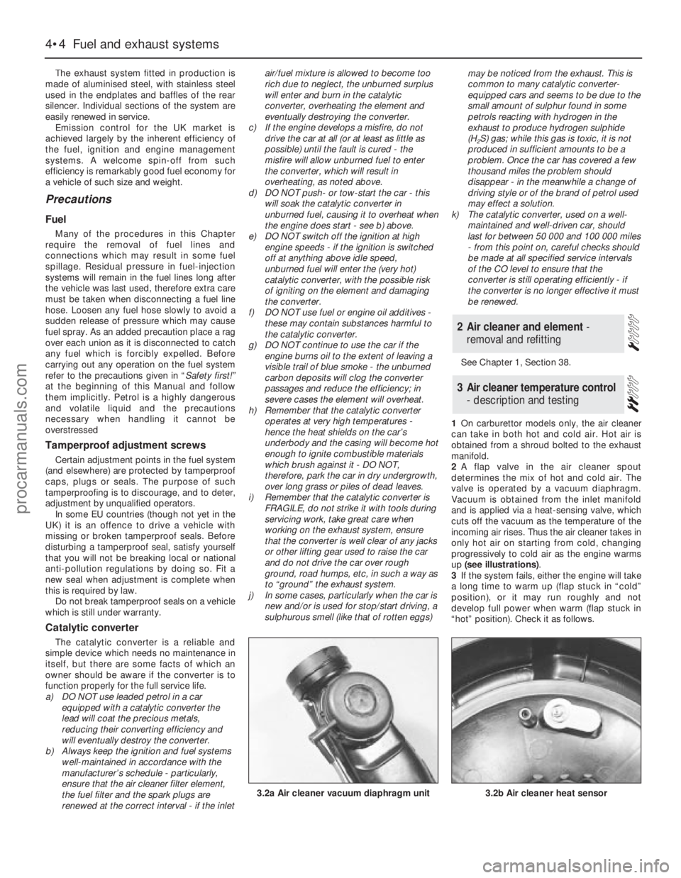
2A flap valve in the air cleaner spout
determines the mix of hot and cold air. The
valve is operated by a vacuum diaphragm.
Vacuum is obtained from the inlet manifold
and is applied via a heat-sensing valve, which
cuts off the vacuum as the temperature of the
incoming air rises. Thus the air cleaner takes in
only hot air on starting from cold, changing
progressively to cold air as the engine warms
up (see illustrations).
3If the system fails, either the engine will take
a long time to warm up (flap stuck in “cold”
position), or it may run roughly and not
develop full power when warm (flap stuck in
“hot” position). Check it as follows.
3Air cleaner temperature control
- description and testing
2Air cleaner and element -
removal and refitting
4•4Fuel and exhaust systems
3.2b Air cleaner heat sensor3.2a Air cleaner vacuum diaphragm unit
procarmanuals.com
Page 150 of 255
6When refitting, screw the track rod end onto
the track rod as far as the locknut, then back it
off half a turn.
7Insert the ball-pin into the steering arm.
Tighten the balljoint nut to the specified torque
and secure with a new split pin. Nip up the
track rod end locknut, but do not tighten it fully
yet.
8Refit the roadwheel, lower the vehicle and
tighten the wheel nuts to the specified torque.
9Check the toe setting as described in the
following Section. (This may not be strictly
necessary if the same track rod end has been
refitted, but is certainly advisable if any
components have been renewed.)
10Tighten the track rod end locknut when
toe is correct.
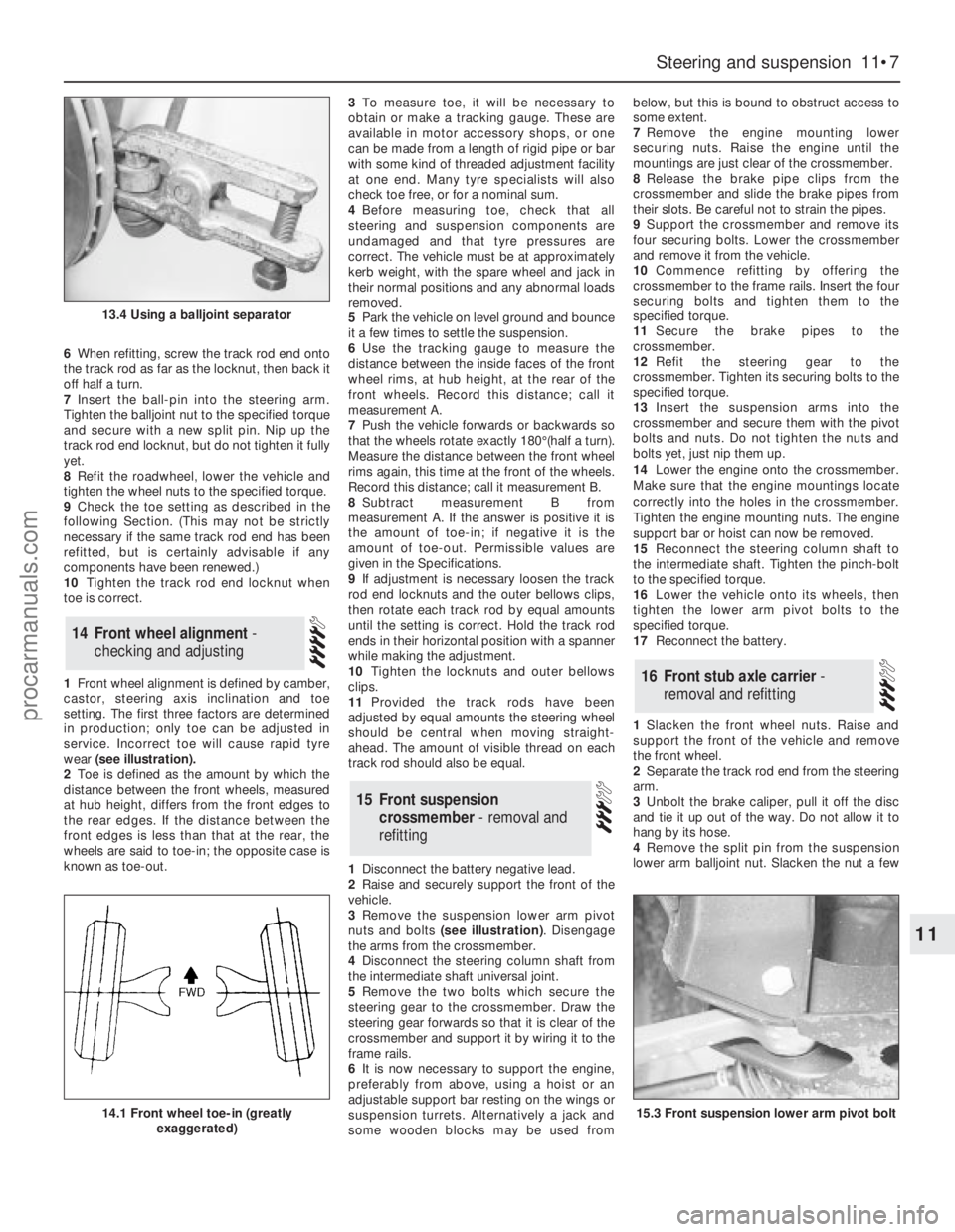
1Front wheel alignment is defined by camber,
castor, steering axis inclination and toe
setting. The first three factors are determined
in production; only toe can be adjusted in
service. Incorrect toe will cause rapid tyre
wear (see illustration).
2Toe is defined as the amount by which the
distance between the front wheels, measured
at hub height, differs from the front edges to
the rear edges. If the distance between the
front edges is less than that at the rear, the
wheels are said to toe-in; the opposite case is
known as toe-out.3To measure toe, it will be necessary to
obtain or make a tracking gauge. These are
available in motor accessory shops, or one
can be made from a length of rigid pipe or bar
with some kind of threaded adjustment facility
at one end. Many tyre specialists will also
check toe free, or for a nominal sum.
4Before measuring toe, check that all
steering and suspension components are
undamaged and that tyre pressures are
correct. The vehicle must be at approximately
kerb weight, with the spare wheel and jack in
their normal positions and any abnormal loads
removed.
5Park the vehicle on level ground and bounce
it a few times to settle the suspension.
6Use the tracking gauge to measure the
distance between the inside faces of the front
wheel rims, at hub height, at the rear of the
front wheels. Record this distance; call it
measurement A.
7Push the vehicle forwards or backwards so
that the wheels rotate exactly 180°(half a turn).
Measure the distance between the front wheel
rims again, this time at the front of the wheels.
Record this distance; call it measurement B.
8Subtract measurement B from
measurement A. If the answer is positive it is
the amount of toe-in; if negative it is the
amount of toe-out. Permissible values are
given in the Specifications.
9If adjustment is necessary loosen the track
rod end locknuts and the outer bellows clips,
then rotate each track rod by equal amounts
until the setting is correct. Hold the track rod
ends in their horizontal position with a spanner
while making the adjustment.
10Tighten the locknuts and outer bellows
clips.
11Provided the track rods have been
adjusted by equal amounts the steering wheel
should be central when moving straight-
ahead. The amount of visible thread on each
track rod should also be equal.
1Disconnect the battery negative lead.
2Raise and securely support the front of the
vehicle.
3Remove the suspension lower arm pivot
nuts and bolts (see illustration). Disengage
the arms from the crossmember.
4Disconnect the steering column shaft from
the intermediate shaft universal joint.
5Remove the two bolts which secure the
steering gear to the crossmember. Draw the
steering gear forwards so that it is clear of the
crossmember and support it by wiring it to the
frame rails.
6It is now necessary to support the engine,
preferably from above, using a hoist or an
adjustable support bar resting on the wings or
suspension turrets. Alternatively a jack and
some wooden blocks may be used frombelow, but this is bound to obstruct access to
some extent.
7Remove the engine mounting lower
securing nuts. Raise the engine until the
mountings are just clear of the crossmember.
8Release the brake pipe clips from the
crossmember and slide the brake pipes from
their slots. Be careful not to strain the pipes.
9Support the crossmember and remove its
four securing bolts. Lower the crossmember
and remove it from the vehicle.
10Commence refitting by offering the
crossmember to the frame rails. Insert the four
securing bolts and tighten them to the
specified torque.
11Secure the brake pipes to the
crossmember.
12Refit the steering gear to the
crossmember. Tighten its securing bolts to the
specified torque.
13Insert the suspension arms into the
crossmember and secure them with the pivot
bolts and nuts. Do not tighten the nuts and
bolts yet, just nip them up.
14Lower the engine onto the crossmember.
Make sure that the engine mountings locate
correctly into the holes in the crossmember.
Tighten the engine mounting nuts. The engine
support bar or hoist can now be removed.
15Reconnect the steering column shaft to
the intermediate shaft. Tighten the pinch-bolt
to the specified torque.
16Lower the vehicle onto its wheels, then
tighten the lower arm pivot bolts to the
specified torque.
17Reconnect the battery.
1Slacken the front wheel nuts. Raise and
support the front of the vehicle and remove
the front wheel.
2Separate the track rod end from the steering
arm.
3Unbolt the brake caliper, pull it off the disc
and tie it up out of the way. Do not allow it to
hang by its hose.
4Remove the split pin from the suspension
lower arm balljoint nut. Slacken the nut a few
16Front stub axle carrier -
removal and refitting
15Front suspension
crossmember - removal and
refitting
14Front wheel alignment -
checking and adjusting
Steering and suspension 11•7
11
13.4 Using a balljoint separator
14.1 Front wheel toe-in (greatly
exaggerated)15.3 Front suspension lower arm pivot bolt
procarmanuals.com
Page 152 of 255
1Raise the vehicle on ramps or on a hoist, so
that the weight is still on the wheels.
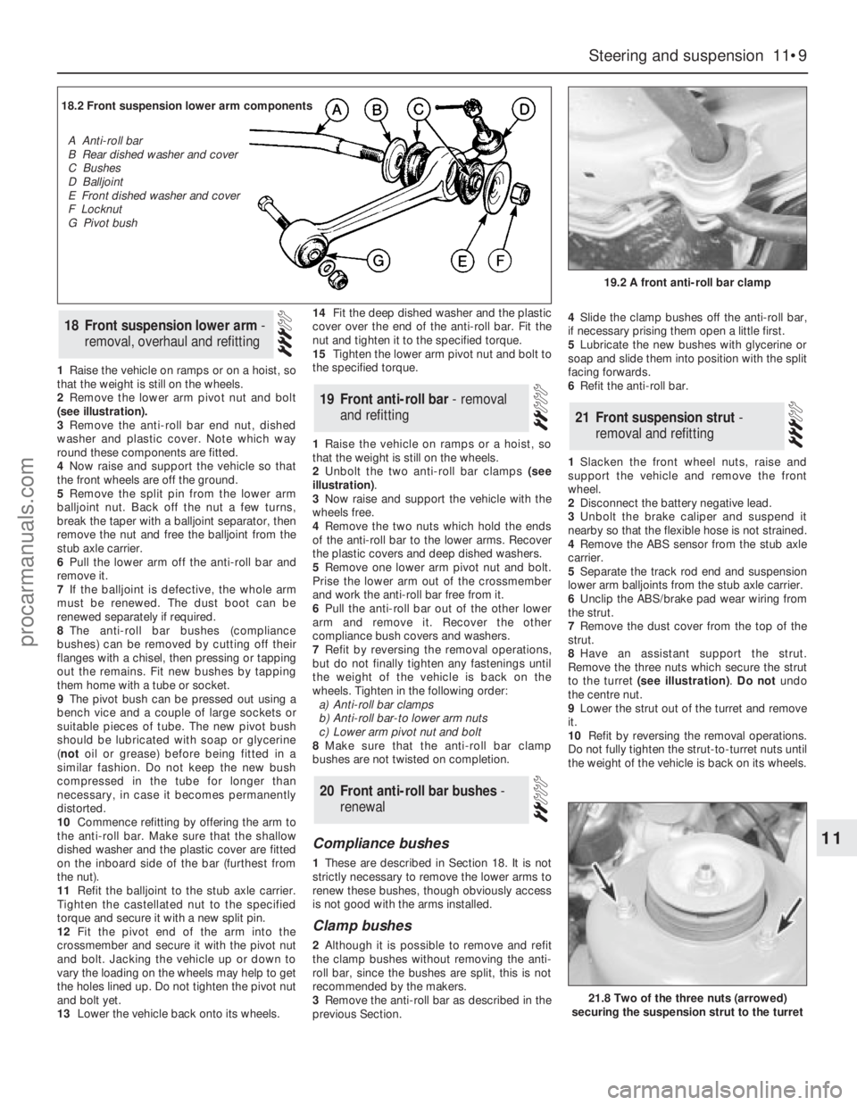
2Remove the lower arm pivot nut and bolt
(see illustration).
3Remove the anti-roll bar end nut, dished
washer and plastic cover. Note which way
round these components are fitted.
4Now raise and support the vehicle so that
the front wheels are off the ground.
5Remove the split pin from the lower arm
balljoint nut. Back off the nut a few turns,
break the taper with a balljoint separator, then
remove the nut and free the balljoint from the
stub axle carrier.
6Pull the lower arm off the anti-roll bar and
remove it.
7If the balljoint is defective, the whole arm
must be renewed. The dust boot can be
renewed separately if required.
8The anti-roll bar bushes (compliance
bushes) can be removed by cutting off their
flanges with a chisel, then pressing or tapping
out the remains. Fit new bushes by tapping
them home with a tube or socket.
9The pivot bush can be pressed out using a
bench vice and a couple of large sockets or
suitable pieces of tube. The new pivot bush
should be lubricated with soap or glycerine
(notoil or grease) before being fitted in a
similar fashion. Do not keep the new bush
compressed in the tube for longer than
necessary, in case it becomes permanently
distorted.
10Commence refitting by offering the arm to
the anti-roll bar. Make sure that the shallow
dished washer and the plastic cover are fitted
on the inboard side of the bar (furthest from
the nut).
11Refit the balljoint to the stub axle carrier.
Tighten the castellated nut to the specified
torque and secure it with a new split pin.
12Fit the pivot end of the arm into the
crossmember and secure it with the pivot nut
and bolt. Jacking the vehicle up or down to
vary the loading on the wheels may help to get
the holes lined up. Do not tighten the pivot nut
and bolt yet.
13Lower the vehicle back onto its wheels.14Fit the deep dished washer and the plastic
cover over the end of the anti-roll bar. Fit the
nut and tighten it to the specified torque.
15Tighten the lower arm pivot nut and bolt to
the specified torque.
1Raise the vehicle on ramps or a hoist, so
that the weight is still on the wheels.
2Unbolt the two anti-roll bar clamps (see
illustration).
3Now raise and support the vehicle with the
wheels free.
4Remove the two nuts which hold the ends
of the anti-roll bar to the lower arms. Recover
the plastic covers and deep dished washers.
5Remove one lower arm pivot nut and bolt.
Prise the lower arm out of the crossmember
and work the anti-roll bar free from it.
6Pull the anti-roll bar out of the other lower
arm and remove it. Recover the other
compliance bush covers and washers.
7Refit by reversing the removal operations,
but do not finally tighten any fastenings until
the weight of the vehicle is back on the
wheels. Tighten in the following order:
a)Anti-roll bar clamps
b)Anti-roll bar-to lower arm nuts
c)Lower arm pivot nut and bolt
8Make sure that the anti-roll bar clamp
bushes are not twisted on completion.
Compliance bushes
1These are described in Section 18. It is not
strictly necessary to remove the lower arms to
renew these bushes, though obviously access
is not good with the arms installed.
Clamp bushes
2Although it is possible to remove and refit
the clamp bushes without removing the anti-
roll bar, since the bushes are split, this is not
recommended by the makers.
3Remove the anti-roll bar as described in the
previous Section.4Slide the clamp bushes off the anti-roll bar,
if necessary prising them open a little first.
5Lubricate the new bushes with glycerine or
soap and slide them into position with the split
facing forwards.
6Refit the anti-roll bar.
1Slacken the front wheel nuts, raise and
support the vehicle and remove the front
wheel.
2Disconnect the battery negative lead.
3Unbolt the brake caliper and suspend it
nearby so that the flexible hose is not strained.
4Remove the ABS sensor from the stub axle
carrier.
5Separate the track rod end and suspension
lower arm balljoints from the stub axle carrier.
6Unclip the ABS/brake pad wear wiring from
the strut.
7Remove the dust cover from the top of the
strut.
8Have an assistant support the strut.
Remove the three nuts which secure the strut
to the turret (see illustration).Do notundo
the centre nut.
9Lower the strut out of the turret and remove
it.
10Refit by reversing the removal operations.
Do not fully tighten the strut-to-turret nuts until
the weight of the vehicle is back on its wheels.
21Front suspension strut -
removal and refitting
20Front anti-roll bar bushes -
renewal
19Front anti-roll bar - removal
and refitting
18Front suspension lower arm -
removal, overhaul and refitting
Steering and suspension 11•9
11
19.2 A front anti-roll bar clamp
21.8 Two of the three nuts (arrowed)
securing the suspension strut to the turret
18.2 Front suspension lower arm components
A Anti-roll bar
B Rear dished washer and cover
C Bushes
D Balljoint
E Front dished washer and cover
F Locknut
G Pivot bush
procarmanuals.com
Page 155 of 255
7Unbolt the guide plate from the body on the
side concerned.
8Carefully lower the jack until the spring is no
longer under tension. Remove the spring and
the rubber buffer.
9Refit by reversing the removal operations,
tightening all fastenings to the specified torque
when known.
Note: Ford tool No 15-014, or locally made
equivalent, will be required for this job.
1Raise and support the rear of the vehicle.
2Flatten the lockwasher which secures the
guide plate centre bolt. Remove the centre
bolt and the two bolts which hold the guide
plate to the floor; remove the guide plate.
3Wedge a piece of wood between the
crossmember and the floor.
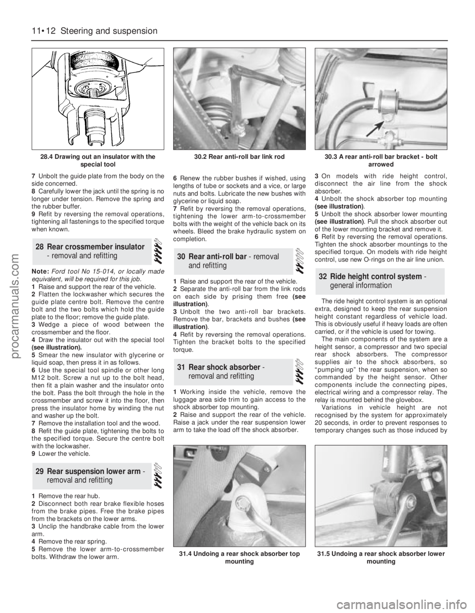
4Draw the insulator out with the special tool
(see illustration).
5Smear the new insulator with glycerine or
liquid soap, then press it in as follows.
6Use the special tool spindle or other long
M12 bolt. Screw a nut up to the bolt head,
then fit a plain washer and the insulator onto
the bolt. Pass the bolt through the hole in the
crossmember and screw it into the floor, then
press the insulator home by winding the nut
and washer up the bolt.
7Remove the installation tool and the wood.
8Refit the guide plate, tightening the bolts to
the specified torque. Secure the centre bolt
with the lockwasher.
9Lower the vehicle.
1Remove the rear hub.
2Disconnect both rear brake flexible hoses
from the brake pipes. Free the brake pipes
from the brackets on the lower arms.
3Unclip the handbrake cable from the lower
arm.
4Remove the rear spring.
5Remove the lower arm-to-crossmember
bolts. Withdraw the lower arm.6Renew the rubber bushes if wished, using
lengths of tube or sockets and a vice, or large
nuts and bolts. Lubricate the new bushes with
glycerine or liquid soap.
7Refit by reversing the removal operations,
tightening the lower arm-to-crossmember
bolts with the weight of the vehicle back on its
wheels. Bleed the brake hydraulic system on
completion.
1Raise and support the rear of the vehicle.
2Separate the anti-roll bar from the link rods
on each side by prising them free (see
illustration).
3Unbolt the two anti-roll bar brackets.
Remove the bar, brackets and bushes (see
illustration).
4Refit by reversing the removal operations.
Tighten the bracket bolts to the specified
torque.
1Working inside the vehicle, remove the
luggage area side trim to gain access to the
shock absorber top mounting.
2Raise and support the rear of the vehicle.
Raise a jack under the rear suspension lower
arm to take the load off the shock absorber.3On models with ride height control,
disconnect the air line from the shock
absorber.
4Unbolt the shock absorber top mounting
(see illustration).
5Unbolt the shock absorber lower mounting
(see illustration). Pull the shock absorber out
of the lower mounting bracket and remove it.
6Refit by reversing the removal operations.
Tighten the shock absorber mountings to the
specified torque. On models with ride height
control, use new O-rings on the air line union.
The ride height control system is an optional
extra, designed to keep the rear suspension
height constant regardless of vehicle load.
This is obviously useful if heavy loads are often
carried, or if the vehicle is used for towing.
The main components of the system are a
height sensor, a compressor and two special
rear shock absorbers. The compressor
supplies air to the shock absorbers, so
“pumping up” the rear suspension, when so
commanded by the height sensor. Other
components include the connecting pipes,
electrical wiring and a compressor relay. The
relay is mounted behind the glovebox.
Variations in vehicle height are not
recognised by the system for approximately
20 seconds, in order to prevent responses to
temporary changes such as those induced by
32Ride height control system -
general information
31Rear shock absorber -
removal and refitting
30Rear anti-roll bar - removal
and refitting
29Rear suspension lower arm -
removal and refitting
28Rear crossmember insulator
- removal and refitting
11•12Steering and suspension
28.4 Drawing out an insulator with the
special tool
31.4 Undoing a rear shock absorber top
mounting31.5 Undoing a rear shock absorber lower
mounting
30.2 Rear anti-roll bar link rod30.3 A rear anti-roll bar bracket - bolt
arrowed
procarmanuals.com