55Release the throttle position sensor wiring
connector from the clip under the throttle
body, and separate the two halves of the
connector.
56Remove the fuel-injectors.
57Check that all relevant wiring, hoses and
pipes have been disconnected to facilitate
removal of the manifold.
58Unscrew the ten bolts and two nuts
securing the inlet manifold to the cylinder
head, and carefully withdraw the manifold.
Recover the gasket.
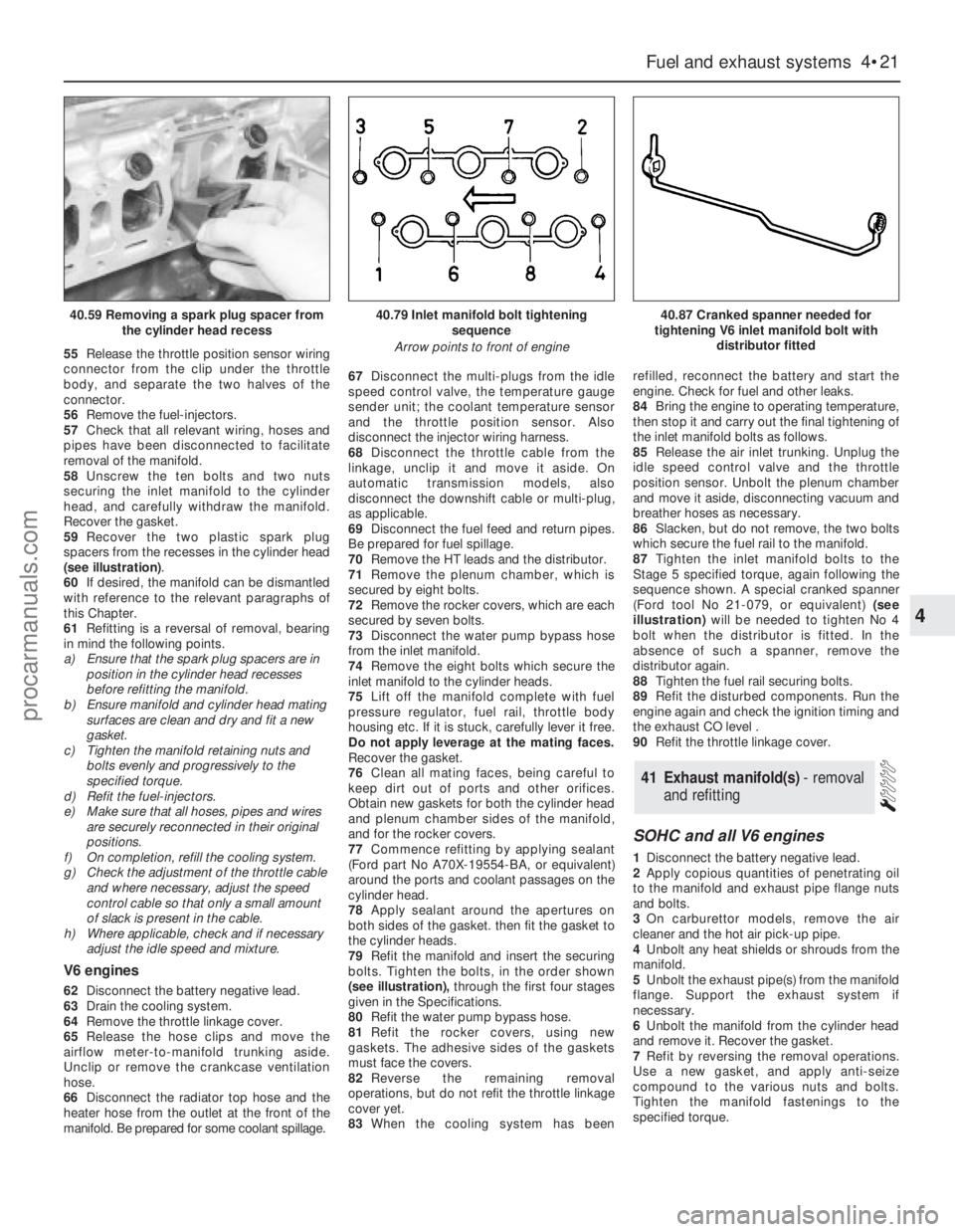
59Recover the two plastic spark plug
spacers from the recesses in the cylinder head
(see illustration).
60If desired, the manifold can be dismantled
with reference to the relevant paragraphs of
this Chapter.
61Refitting is a reversal of removal, bearing
in mind the following points.
a)Ensure that the spark plug spacers are in
position in the cylinder head recesses
before refitting the manifold.
b)Ensure manifold and cylinder head mating
surfaces are clean and dry and fit a new
gasket.
c)Tighten the manifold retaining nuts and
bolts evenly and progressively to the
specified torque.
d)Refit the fuel-injectors.
e)Make sure that all hoses, pipes and wires
are securely reconnected in their original
positions.
f)On completion, refill the cooling system.
g)Check the adjustment of the throttle cable
and where necessary, adjust the speed
control cable so that only a small amount
of slack is present in the cable.
h)Where applicable, check and if necessary
adjust the idle speed and mixture.
V6 engines
62Disconnect the battery negative lead.
63Drain the cooling system.
64Remove the throttle linkage cover.
65Release the hose clips and move the
airflow meter-to-manifold trunking aside.
Unclip or remove the crankcase ventilation
hose.
66Disconnect the radiator top hose and the
heater hose from the outlet at the front of the
manifold. Be prepared for some coolant spillage.67Disconnect the multi-plugs from the idle
speed control valve, the temperature gauge
sender unit; the coolant temperature sensor
and the throttle position sensor. Also
disconnect the injector wiring harness.
68Disconnect the throttle cable from the
linkage, unclip it and move it aside. On
automatic transmission models, also
disconnect the downshift cable or multi-plug,
as applicable.
69Disconnect the fuel feed and return pipes.
Be prepared for fuel spillage.
70Remove the HT leads and the distributor.
71Remove the plenum chamber, which is
secured by eight bolts.
72Remove the rocker covers, which are each
secured by seven bolts.
73Disconnect the water pump bypass hose
from the inlet manifold.
74Remove the eight bolts which secure the
inlet manifold to the cylinder heads.
75Lift off the manifold complete with fuel
pressure regulator, fuel rail, throttle body
housing etc. If it is stuck, carefully lever it free.
Do not apply leverage at the mating faces.
Recover the gasket.
76Clean all mating faces, being careful to
keep dirt out of ports and other orifices.
Obtain new gaskets for both the cylinder head
and plenum chamber sides of the manifold,
and for the rocker covers.
77Commence refitting by applying sealant
(Ford part No A70X-19554-BA, or equivalent)
around the ports and coolant passages on the
cylinder head.
78Apply sealant around the apertures on
both sides of the gasket. then fit the gasket to
the cylinder heads.
79Refit the manifold and insert the securing
bolts. Tighten the bolts, in the order shown
(see illustration),through the first four stages
given in the Specifications.
80Refit the water pump bypass hose.
81Refit the rocker covers, using new
gaskets. The adhesive sides of the gaskets
must face the covers.
82Reverse the remaining removal
operations, but do not refit the throttle linkage
cover yet.
83When the cooling system has beenrefilled, reconnect the battery and start the
engine. Check for fuel and other leaks.
84Bring the engine to operating temperature,
then stop it and carry out the final tightening of
the inlet manifold bolts as follows.
85Release the air inlet trunking. Unplug the
idle speed control valve and the throttle
position sensor. Unbolt the plenum chamber
and move it aside, disconnecting vacuum and
breather hoses as necessary.
86Slacken, but do not remove, the two bolts
which secure the fuel rail to the manifold.
87Tighten the inlet manifold bolts to the
Stage 5 specified torque, again following the
sequence shown. A special cranked spanner
(Ford tool No 21-079, or equivalent)(see
illustration)will be needed to tighten No 4
bolt when the distributor is fitted. In the
absence of such a spanner, remove the
distributor again.
88Tighten the fuel rail securing bolts.
89Refit the disturbed components. Run the
engine again and check the ignition timing and
the exhaust CO level .
90Refit the throttle linkage cover.
SOHC and all V6 engines
1Disconnect the battery negative lead.
2Apply copious quantities of penetrating oil
to the manifold and exhaust pipe flange nuts
and bolts.
3On carburettor models, remove the air
cleaner and the hot air pick-up pipe.
4Unbolt any heat shields or shrouds from the
manifold.
5Unbolt the exhaust pipe(s) from the manifold
flange. Support the exhaust system if
necessary.
6Unbolt the manifold from the cylinder head
and remove it. Recover the gasket.
7Refit by reversing the removal operations.
Use a new gasket, and apply anti-seize
compound to the various nuts and bolts.
Tighten the manifold fastenings to the
specified torque.
41Exhaust manifold(s) - removal
and refitting
Fuel and exhaust systems 4•21
4
40.59 Removing a spark plug spacer from
the cylinder head recess40.79 Inlet manifold bolt tightening
sequence
Arrow points to front of engine40.87 Cranked spanner needed for
tightening V6 inlet manifold bolt with
distributor fitted
procarmanuals.com