1985 FORD GRANADA power steering
[x] Cancel search: power steeringPage 28 of 255
The cylinder head is of crossflow design
with the inlet manifold mounted on the left-
hand side and the exhaust manifold mounted
on the right-hand side.
Lubrication is by means of a bi-rotor pump
which draws oil through a strainer located
inside the sump, and forces it through a full-
flow filter into the engine oil galleries where it
is distributed to the crankshaft, camshaft and
auxiliary shaft. The big-end bearings are
supplied with oil via internal drillings in the
crankshaft.The undersides of the pistons are
supplied with oil from drillings in the big-ends.
The distributor shaft is intermittently supplied
with oil from the drilled auxiliary shaft. The
camshaft and cam followers are supplied with
oil via a drilled spray tube from the centre
camshaft bearing.
A semi-closed crankcase ventilation system
is employed whereby piston blow-by gases
are drawn into the inlet manifold via an oil
separator and on carburettor models a control
valve.
The following operations can be carried out
without removing the engine, although the
work may be easier and quicker with the
engine removed:
a)Removal and refitting of the cylinder head
b)Removal and refitting of the camshaft
(after removing the cylinder head)
c)Removal and refitting of the timing belt
and sprockets
d)Removal and refitting of the sump and oil
pump
e)Removal and refitting of the pistons,
connecting rods and big-end bearings
f)Renewal of the engine mountings
g)Renewal of the crankshaft oil seals
h)Removal and refitting of the auxiliary shaft
j)Removal and refitting of the flywheel
The engine must be removed from the
vehicle for the following operations:
a)Renewal of the crankshaft main bearings
b)Removal and refitting of the crankshaft
The engine may be lifted out either on its
own or together with the gearbox. Unless work
is also necessary on the gearbox it is
recommended that the engine is removed on
its own. Where automatic transmission is
fitted, the engine should be removed on its
own owing to the additional weight. If the
engine and gearbox are removed together,
they will have to be tilted at a very steep angle;
make sure that the range of the lifting tackle is
adequate.1Disconnect the battery negative lead.
2Remove the bonnet.
3On carburettor models, remove the air
cleaner. On fuel-injection models, remove the
air cleaner cover, vane airflow meter and air
inlet trunking.
4If a splash guard is fitted, remove it.
5Release the securing clips and bolts and
remove the upper half of the fan shroud. On
carburettor models remove the lower half of
the shroud too.
6Drain the cooling system.
7Disconnect the radiator top and bottom
hoses from the thermostat housing and water
pump. Disconnect the top hose spur from the
expansion tank and unclip it.
8Disconnect the heater hoses from the water
pump and from the inlet manifold or automatic
choke housing. Unclip the hoses.
9On models with power steering, remove the
steering pump.
10Disconnect the vacuum pipe(s) from the
inlet manifold, labelling them if there is any
possibility of confusion.
11Disconnect the following wiring, as
applicable:
a)Alternator
b)Temperature gauge sender
c)Engine management temperature sensor
d)Distributor
e)Oil pressure switch
f)Automatic choke and thermo-switch
g)Carburettor stepper motor
h)Fuel-injection system sub-harness
j)Inlet manifold heater
12Disconnect the HT lead from the coil.
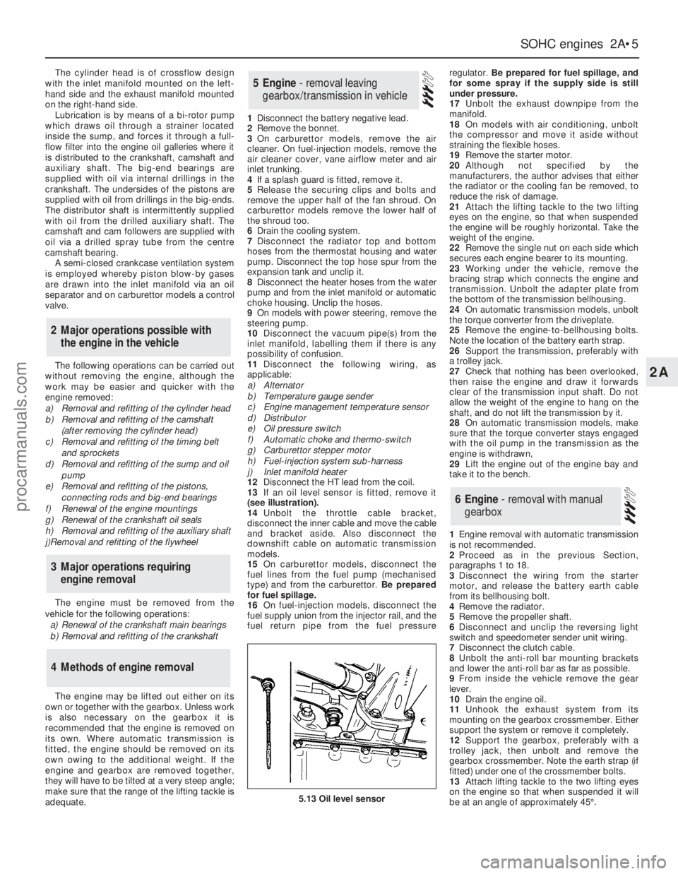
13If an oil level sensor is fitted, remove it
(see illustration).
14Unbolt the throttle cable bracket,
disconnect the inner cable and move the cable
and bracket aside. Also disconnect the
downshift cable on automatic transmission
models.
15On carburettor models, disconnect the
fuel lines from the fuel pump (mechanised
type) and from the carburettor. Be prepared
for fuel spillage.
16On fuel-injection models, disconnect the
fuel supply union from the injector rail, and the
fuel return pipe from the fuel pressureregulator. Be prepared for fuel spillage, and
for some spray if the supply side is still
under pressure.
17Unbolt the exhaust downpipe from the
manifold.
18On models with air conditioning, unbolt
the compressor and move it aside without
straining the flexible hoses.
19Remove the starter motor.
20Although not specified by the
manufacturers, the author advises that either
the radiator or the cooling fan be removed, to
reduce the risk of damage.
21Attach the lifting tackle to the two lifting
eyes on the engine, so that when suspended
the engine will be roughly horizontal. Take the
weight of the engine.
22Remove the single nut on each side which
secures each engine bearer to its mounting.
23Working under the vehicle, remove the
bracing strap which connects the engine and
transmission. Unbolt the adapter plate from
the bottom of the transmission bellhousing.
24On automatic transmission models, unbolt
the torque converter from the driveplate.
25Remove the engine-to-bellhousing bolts.
Note the location of the battery earth strap.
26Support the transmission, preferably with
a trolley jack.
27Check that nothing has been overlooked,
then raise the engine and draw it forwards
clear of the transmission input shaft. Do not
allow the weight of the engine to hang on the
shaft, and do not lift the transmission by it.
28On automatic transmission models, make
sure that the torque converter stays engaged
with the oil pump in the transmission as the
engine is withdrawn,
29Lift the engine out of the engine bay and
take it to the bench.
1Engine removal with automatic transmission
is not recommended.
2Proceed as in the previous Section,
paragraphs 1 to 18.
3Disconnect the wiring from the starter
motor, and release the battery earth cable
from its bellhousing bolt.
4Remove the radiator.
5Remove the propeller shaft.
6Disconnect and unclip the reversing light
switch and speedometer sender unit wiring.
7Disconnect the clutch cable.
8Unbolt the anti-roll bar mounting brackets
and lower the anti-roll bar as far as possible.
9From inside the vehicle remove the gear
lever.
10Drain the engine oil.
11Unhook the exhaust system from its
mounting on the gearbox crossmember. Either
support the system or remove it completely.
12Support the gearbox, preferably with a
trolley jack, then unbolt and remove the
gearbox crossmember. Note the earth strap (if
fitted) under one of the crossmember bolts.
13Attach lifting tackle to the two lifting eyes
on the engine so that when suspended it will
be at an angle of approximately 45°.
6Engine - removal with manual
gearbox
5Engine - removal leaving
gearbox/transmission in vehicle
4Methods of engine removal
3Major operations requiring
engine removal
2Major operations possible with
the engine in the vehicle
SOHCengines 2A•5
2A
5.13 Oil level sensor
procarmanuals.com
Page 43 of 255
See Chapter 1, Section 23.
1Make a final check to ensure that everything
has been reconnected to the engine and that no
rags or tools have been left in the engine bay.
2Check that oil and coolant levels are
correct.
3Start the engine. This may take a little longer
than usual as fuel is pumped up to the engine.
4Check that the oil pressure light goes out
when the engine starts.
5Run the engine at a fast tickover and check
for leaks of oil, fuel and coolant. Also check
power steering and transmission fluid cooler
unions, when applicable. Some smoke and
odd smells may be experienced as assembly
lubricant burns off the exhaust manifold and
other components.6Bring the engine to operating temperature.
Check the ignition timing then adjust the idle
speed (if applicable) and mixture.
7Stop the engine and allow it to cool, then re-
check the oil and coolant levels.
8If new bearings, pistons etc have been
fitted, the engine should be run in at reduced
speeds and loads for the first 500 miles (800
km) or so. It is beneficial to change the engine
oil and filter after this mileage.
1When engine performance is down, or if
misfiring occurs which cannot be attributed to
the ignition or fuel system, a compression test
can provide diagnostic clues. If the test is
performed regularly it can give warning of
trouble before any other symptoms become
apparent.
2The engine must be at operating
temperature, the battery must be fully charged
and the spark plugs must be removed. The
services of an assistant will also be required.
3Disable the ignition system by dismantlingthe coil LT feed. Fit the compression tester to
No 1 spark plug hole. (The type of tester which
screws into the spark plug hole is to be
preferred.)
4Have the assistant hold the throttle wide
open and crank the engine on the starter.
Record the highest reading obtained on the
compression tester.
5Repeat the test on the remaining cylinders,
recording the pressure developed in each.
6Desired pressures are given in the
Specifications. If the pressure in any cylinder
is low, introduce a teaspoonful of clean engine
oil into the spark plug hole and repeat the test.
7If the addition of oil temporarily improves
the compression pressure, this indicates that
bore or piston wear was responsible for the
pressure loss. No improvement suggests that
leaking or burnt valves, or a blown head
gasket, may be to blame.
8A low reading from two adjacent cylinders is
almost certainly due to the head gasket
between them having blown.
9On completion of the test, refit the spark
plugs and reconnect the coil LT feed.
52Compression test -
description and interpretation
51Initial start-up after overhaul
or major repair
50Valve clearances - checking
and adjustment
2A•20SOHCengines
procarmanuals.com
Page 47 of 255
manifold. Piston blow-by gases are drawn
through the oil separator and the vent valve to
the inlet manifold. The blow-by gases are then
drawn into the engine together with the fuel/air
mixture. Refer to Chapter 1 for maintenance of
the system.
The following operations can be carried out
without removing the engine from the vehicle.
a)Removal of the camshafts.
b)Removal and servicing of the cylinder
head.
c)Removal of the timing chain and
sprockets.
d)Removal of the oil pump.
e)Removal of the sump.
f)Removal of the pistons and connecting
rods.
g)Removal of the big-end bearings.
h)Removal of the engine mountings.
i)Removal of the clutch and flywheel.
j)Removal of the crankshaft front and rear
oil seals.
The following operations can only be carried
out after removing the engine from the vehicle.
a)Removal of the crankshaft main bearings.
b)Removal of the crankshaft.
Note: A hoist and lifting tackle will be required
to lift the engine out of the vehicle.
1Disconnect the battery negative lead.
2Remove the bonnet.
3On carburettor models, remove the air cleaner.
4On fuel-injection models, remove the air
inlet hose, plenum chamber and air cleaner lid
as an assembly.
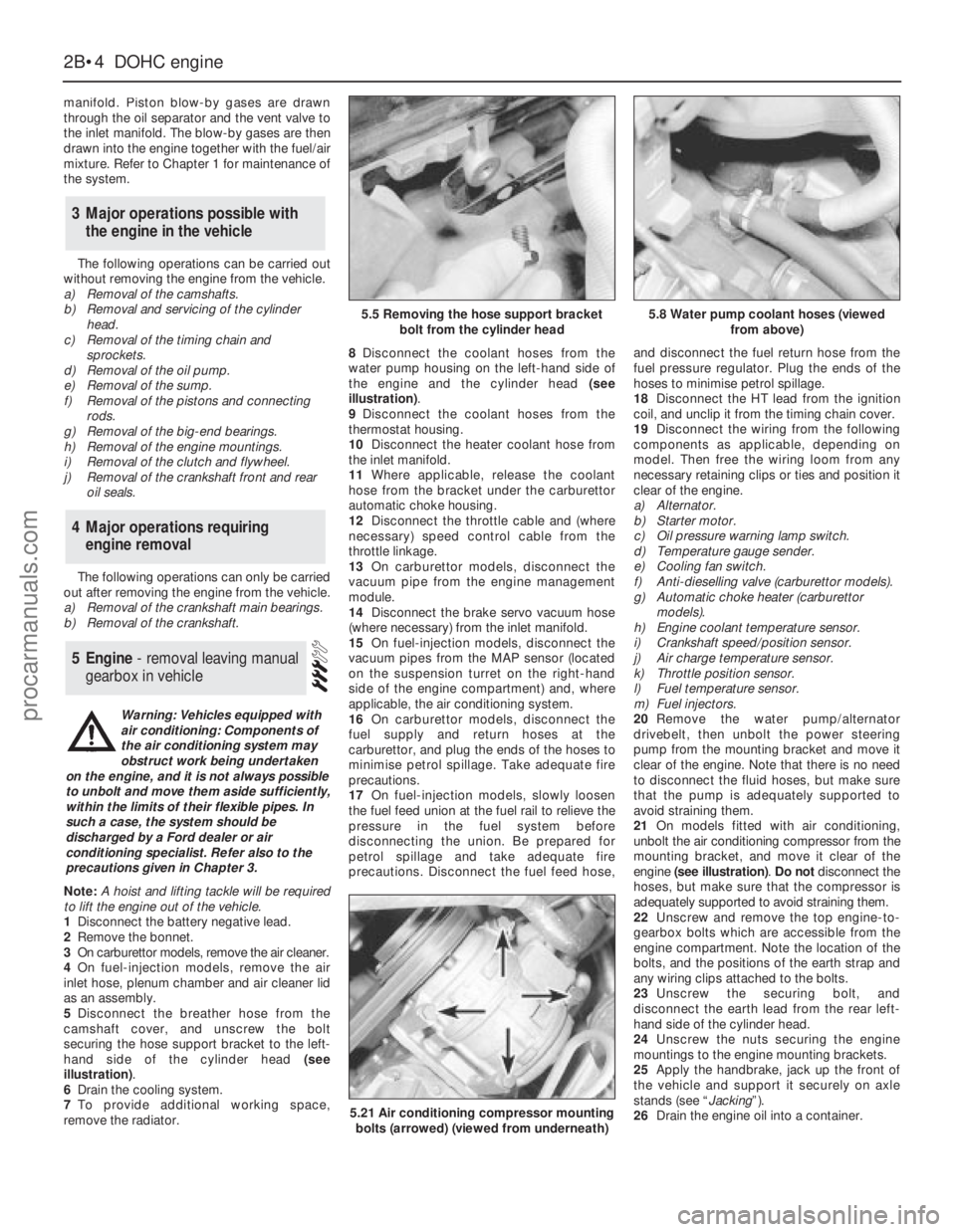
5Disconnect the breather hose from the
camshaft cover, and unscrew the bolt
securing the hose support bracket to the left-
hand side of the cylinder head (see
illustration).
6Drain the cooling system.
7To provide additional working space,
remove the radiator.8Disconnect the coolant hoses from the
water pump housing on the left-hand side of
the engine and the cylinder head (see
illustration).
9Disconnect the coolant hoses from the
thermostat housing.
10Disconnect the heater coolant hose from
the inlet manifold.
11Where applicable, release the coolant
hose from the bracket under the carburettor
automatic choke housing.
12Disconnect the throttle cable and (where
necessary) speed control cable from the
throttle linkage.
13On carburettor models, disconnect the
vacuum pipe from the engine management
module.
14Disconnect the brake servo vacuum hose
(where necessary) from the inlet manifold.
15On fuel-injection models, disconnect the
vacuum pipes from the MAP sensor (located
on the suspension turret on the right-hand
side of the engine compartment) and, where
applicable, the air conditioning system.
16On carburettor models, disconnect the
fuel supply and return hoses at the
carburettor, and plug the ends of the hoses to
minimise petrol spillage. Take adequate fire
precautions.
17On fuel-injection models, slowly loosen
the fuel feed union at the fuel rail to relieve the
pressure in the fuel system before
disconnecting the union. Be prepared for
petrol spillage and take adequate fire
precautions. Disconnect the fuel feed hose,and disconnect the fuel return hose from the
fuel pressure regulator. Plug the ends of the
hoses to minimise petrol spillage.
18Disconnect the HT lead from the ignition
coil, and unclip it from the timing chain cover.
19Disconnect the wiring from the following
components as applicable, depending on
model. Then free the wiring loom from any
necessary retaining clips or ties and position it
clear of the engine.
a)Alternator.
b)Starter motor.
c)Oil pressure warning lamp switch.
d)Temperature gauge sender.
e)Cooling fan switch.
f)Anti-dieselling valve (carburettor models).
g)Automatic choke heater (carburettor
models).
h)Engine coolant temperature sensor.
i)Crankshaft speed/position sensor.
j)Air charge temperature sensor.
k)Throttle position sensor.
l)Fuel temperature sensor.
m)Fuel injectors.
20Remove the water pump/alternator
drivebelt, then unbolt the power steering
pump from the mounting bracket and move it
clear of the engine. Note that there is no need
to disconnect the fluid hoses, but make sure
that the pump is adequately supported to
avoid straining them.
21On models fitted with air conditioning,
unbolt the air conditioning compressor from the
mounting bracket, and move it clear of the
engine (see illustration). Do notdisconnect the
hoses, but make sure that the compressor is
adequately supported to avoid straining them.
22Unscrew and remove the top engine-to-
gearbox bolts which are accessible from the
engine compartment. Note the location of the
bolts, and the positions of the earth strap and
any wiring clips attached to the bolts.
23Unscrew the securing bolt, and
disconnect the earth lead from the rear left-
hand side of the cylinder head.
24Unscrew the nuts securing the engine
mountings to the engine mounting brackets.
25Apply the handbrake, jack up the front of
the vehicle and support it securely on axle
stands (see “Jacking”).
26Drain the engine oil into a container.
5Engine - removal leaving manual
gearbox in vehicle
4Major operations requiring
engine removal
3Major operations possible with
the engine in the vehicle
2B•4DOHCengine
5.5 Removing the hose support bracket
bolt from the cylinder head5.8 Water pump coolant hoses (viewed
from above)
5.21 Air conditioning compressor mounting
bolts (arrowed) (viewed from underneath)
Warning: Vehicles equipped with
air conditioning: Components of
the air conditioning system may
obstruct work being undertaken
on the engine, and it is not always possible
to unbolt and move them aside sufficiently,
within the limits of their flexible pipes. In
such a case, the system should be
discharged by a Ford dealer or air
conditioning specialist. Refer also to the
precautions given in Chapter 3.
procarmanuals.com
Page 69 of 255
Other items
34Disconnect the throttle cable from the
operating lever and bracket.
35Disconnect the right-hand exhaust
downpipe from the manifold then remove the
starter motor, the oil filter, and disconnect the
left-hand exhaust downpipe, in that order.
Refer to Part A, Section 8, paragraphs 1 to 8
of this Chapter.
Cylinder head bolts on the V6 engine may
be conventional (hexagon-headed) or Torx
type. The appropriate Torx key will be needed
to deal with the latter.
Before dismantling the engine into its main
components, the following ancillaries can be
removed. The actual items removed, and the
sequence of removal, will depend on the work
to be done.
Distributor and bracket
Spark plugs
Inlet manifold and associated items
Exhaust manifolds
Clutch
Alternator and bracket
Oil pressure switch(see illustration) Temperature gauge sender
Engine bearer arms
Dipstick
If an oil cooler is fitted between the oil filter
and the block, remove it by disconnecting the
coolant hoses and unscrewing the central
sleeve. The cooler and seal can now be
removed. If the threaded bush is removed
from the block (it may come out with the
sleeve) it must be renewed.
The procedure is described for the engine in
the vehicle. With the engine removed, the
preliminary steps can be ignored.
2.8 litre engine
1Disconnect the battery negative lead.
2Remove the inlet manifold and associated
components.
3Unbolt the power steering pump, remove
the drivebelts and move the pump aside.
Support it by wiring it to adjacent
components.
4Remove the alternator and its bracket.
5Remove the three bolts which secure each
rocker shaft. Remove the shafts and
pushrods, keeping them in order so that they
can be refitted in the same locations.
6Unbolt the exhaust pipes from the
manifolds.
7Remove the spark plugs.8Slacken the cylinder head bolts half a turn at
a time, following the reverse sequence to that
used when tightening (see illustration 38.5).
Remove the bolts.
9Remove the cylinder heads. If they are
stuck, try to rock them free, or tap them with a
soft-faced hammer. Do nothit them directly
with a metal hammer, and do notlever in
between the joint faces.
10Recover the head gaskets.
2.4 & 2.9 litre engines
11Disconnect the battery and drain the
cooling system.
12Disconnect the radiator top hose and the
heater hose from the thermostat housing.
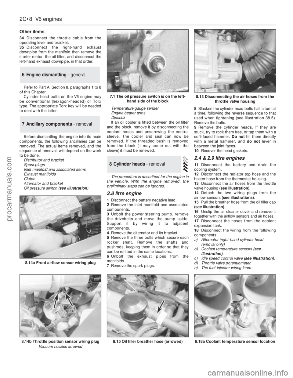
13Disconnect the air hoses from the throttle
valve housing (see illustration).
14Detach the two wiring plugs from the
airflow sensors (see illustrations).
15Pull the breather hose from the oil filler cap
(see illustration).
16Unclip the air cleaner cover and remove it
together with the airflow sensors and air hoses.
17Disconnect the hoses from the coolant
expansion tank.
18Disconnect the wiring from the following
components:
a)Alternator (right-hand cylinder head
removal only).
b)Coolant temperature sensors(see
illustration).
c)Idle speed control valve (see illustration).
d)Throttle valve potentiometer.
e)The fuel-injector wiring loom.8Cylinder heads - removal
7Ancillary components - removal
6Engine dismantling - general
2C•8V6 engines
7.1 The oil pressure switch is on the left-
hand side of the block
8.14b Throttle position sensor wiring plug
Vacuum nozzles arrowed
8.14a Front airflow sensor wiring plug
8.15 Oil filler breather hose (arrowed)8.18a Coolant temperature sensor location
8.13 Disconnecting the air hoses from the
throttle valve housing
procarmanuals.com
Page 70 of 255
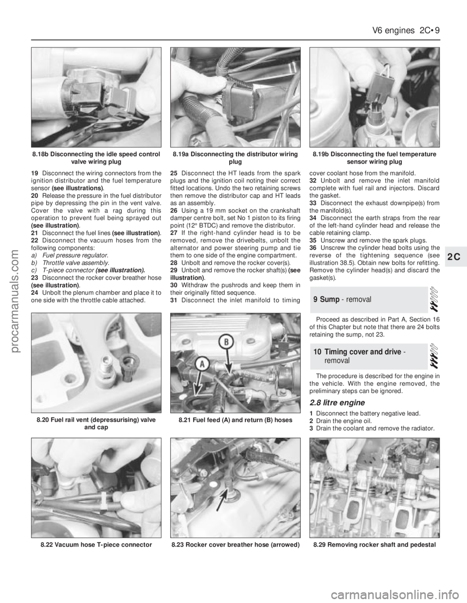
19Disconnect the wiring connectors from the
ignition distributor and the fuel temperature
sensor (see illustrations).
20Release the pressure in the fuel distributor
pipe by depressing the pin in the vent valve.
Cover the valve with a rag during this
operation to prevent fuel being sprayed out
(see illustration).
21Disconnect the fuel lines (see illustration).
22Disconnect the vacuum hoses from the
following components:
a)Fuel pressure regulator.
b)Throttle valve assembly.
c)T-piece connector (see illustration).
23Disconnect the rocker cover breather hose
(see illustration).
24Unbolt the plenum chamber and place it to
one side with the throttle cable attached.25Disconnect the HT leads from the spark
plugs and the ignition coil noting their correct
fitted locations. Undo the two retaining screws
then remove the distributor cap and HT leads
as an assembly.
26Using a 19 mm socket on the crankshaft
damper centre bolt, set No 1 piston to its firing
point (12°BTDC) and remove the distributor.
27If the right-hand cylinder head is to be
removed, remove the drivebelts, unbolt the
alternator and power steering pump and tie
them to one side of the engine compartment.
28Unbolt and remove the rocker cover(s).
29Unbolt and remove the rocker shaft(s) (see
illustration).
30Withdraw the pushrods and keep them in
their originally fitted sequence.
31Disconnect the inlet manifold to timingcover coolant hose from the manifold.
32Unbolt and remove the inlet manifold
complete with fuel rail and injectors. Discard
the gasket.
33Disconnect the exhaust downpipe(s) from
the manifold(s).
34Disconnect the earth straps from the rear
of the left-hand cylinder head and release the
cable retaining clamp.
35Unscrew and remove the spark plugs.
36Unscrew the cylinder head bolts using the
reverse of the tightening sequence (see
illustration 38.5). Obtain new bolts for refitting.
Remove the cylinder head(s) and discard the
gasket(s).
Proceed as described in Part A, Section 16
of this Chapter but note that there are 24 bolts
retaining the sump, not 23.
The procedure is described for the engine in
the vehicle. With the engine removed, the
preliminary steps can be ignored.
2.8 litre engine
1Disconnect the battery negative lead.
2Drain the engine oil.
3Drain the coolant and remove the radiator.
10Timing cover and drive -
removal
9Sump - removal
V6 engines 2C•9
2C
8.18b Disconnecting the idle speed control
valve wiring plug8.19a Disconnecting the distributor wiring
plug8.19b Disconnecting the fuel temperature
sensor wiring plug
8.22 Vacuum hose T-piece connector
8.20 Fuel rail vent (depressurising) valve
and cap8.21 Fuel feed (A) and return (B) hoses
8.23 Rocker cover breather hose (arrowed)8.29 Removing rocker shaft and pedestal
procarmanuals.com
Page 71 of 255
4Remove the auxiliary drivebelts.
5Remove the fan and viscous clutch if fitted).
6Jam the crankshaft, either by engaging 5th
gear and applying the handbrake, or by
removing the starter motor and having an
assistant jam a screwdriver in the starter ring
gear teeth. Unbolt the crankshaft pulley. When
the pulley is secured to a vibration damper,
also remove the damper central bolt.
7Remove the pulley or damper, using a puller
if necessary.
8Disconnect the coolant hoses from the front
of the engine, including the water pump
bypass hose.
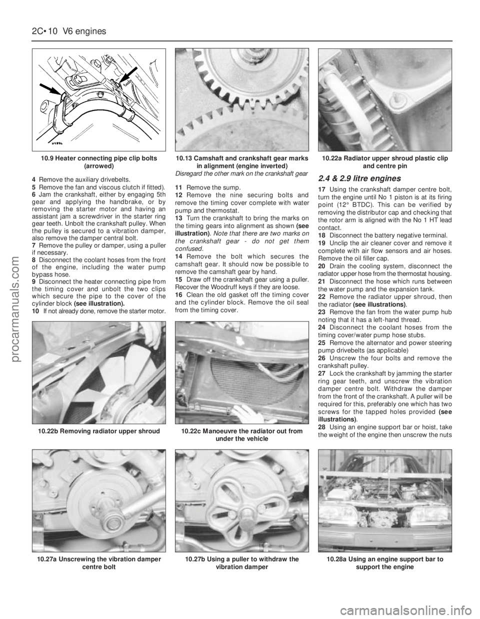
9Disconnect the heater connecting pipe from
the timing cover and unbolt the two clips
which secure the pipe to the cover of the
cylinder block (see illustration).
10If not already done, remove the starter motor.11Remove the sump.
12Remove the nine securing bolts and
remove the timing cover complete with water
pump and thermostat.
13Turn the crankshaft to bring the marks on
the timing gears into alignment as shown (see
illustration). Note that there are two marks on
the crankshaft gear - do not get them
confused.
14Remove the bolt which secures the
camshaft gear. It should now be possible to
remove the camshaft gear by hand.
15Draw off the crankshaft gear using a puller.
Recover the Woodruff keys if they are loose.
16Clean the old gasket off the timing cover
and the cylinder block. Remove the oil seal
from the timing cover.2.4 & 2.9 litre engines
17Using the crankshaft damper centre bolt,
turn the engine until No 1 piston is at its firing
point (12°BTDC). This can be verified by
removing the distributor cap and checking that
the rotor arm is aligned with the No 1 HT lead
contact.
18Disconnect the battery negative terminal.
19Unclip the air cleaner cover and remove it
complete with air flow sensors and air hoses.
Remove the oil filler cap.
20Drain the cooling system, disconnect the
radiator upper hose from the thermostat housing.
21Disconnect the hose which runs between
the water pump and the expansion tank.
22Remove the radiator upper shroud, then
the radiator (see illustrations).
23Remove the fan from the water pump hub
noting that it has a left-hand thread.
24Disconnect the coolant hoses from the
timing cover/water pump hose stubs.
25Remove the alternator and power steering
pump drivebelts (as applicable)
26Unscrew the four bolts and remove the
crankshaft pulley.
27Lock the crankshaft by jamming the starter
ring gear teeth, and unscrew the vibration
damper centre bolt. Withdraw the damper
from the front of the crankshaft. A puller will be
required for this, preferably one which has two
screws for the tapped holes provided (see
illustrations).
28Using an engine support bar or hoist, take
the weight of the engine then unscrew the nuts
2C•10V6 engines
10.9 Heater connecting pipe clip bolts
(arrowed)
10.27a Unscrewing the vibration damper
centre bolt
10.22b Removing radiator upper shroud10.22c Manoeuvre the radiator out from
under the vehicle
10.27b Using a puller to withdraw the
vibration damper10.28a Using an engine support bar to
support the engine
10.13 Camshaft and crankshaft gear marks
in alignment (engine inverted)
Disregard the other mark on the crankshaft gear10.22a Radiator upper shroud plastic clip
and centre pin
procarmanuals.com
Page 80 of 255
29Fit the sump and the retaining nuts and
bolts. Tighten them progressively in two stages.
30Oil the lip of the timing cover oil seal and
the contact surface of the crankshaft damper.
31Fit the damper to the crankshaft, being
careful not to dislodge the Woodruff key. Draw
the damper into position using the retaining
bolt and washer.
32Remove the bolt and apply sealant to the
faces of the washer. Refit the bolt and washer
then jam the starter gear ring teeth and tighten
the bolt to the specified torque.
33Refit the crankshaft pulley and tighten the
retaining bolts to the specified torque.
34Refit the crossmember side brackets and
brake pipes.
35Reconnect the engine mountings and
remove the engine hoist or axle stands (see
“Jacking”).36Connect the steering shaft coupling with
the steering wheel and front roadwheels in the
straight-ahead position. Fit the pinch-bolt and
tighten it to the specified torque.
37Fit the starter motor and connect the leads.
38Bolt the coolant distributor pipe to the
timing cover.
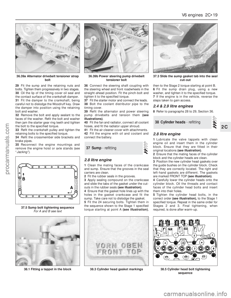
39Refit the alternator and power steering
pump drivebelts and tension them (see
illustrations).
40Fit the fan and radiator, connect all coolant
hoses, and fit the radiator upper shroud.
41Fit the air cleaner cover with attachments.
42Fill the engine with oil and coolant and
connect the battery.
2.8 litre engine
1Clean the mating faces of the crankcase
and sump. Ensure that the grooves in the seal
carriers are clean.
2Fit the rubber seals in the grooves.
3Apply sealing compound on the crankcase
and slide the tabs of the gasket under the cut-
outs in the rubber seals (see illustration).
4Ensure that the gasket hole lines up with the
holes in the gasket crankcase and fit the
sump. Take care not to dislodge the gasket.
5Fit the 24 securing bolts. Tighten them in
the sequence shown to the Stage 1 specified
torque starting at point A (see illustration),then to the Stage 2 torque starting at point B.
6Fit the sump drain plug, using a new
washer, and tighten it to the specified torque.
7If the engine is in the vehicle, reverse the
steps taken to gain access.
2.4 & 2.9 litre engines
8Refer to paragraphs 28 to 29, Section 36.
2.8 litre engine
1Lubricate the valve tappets with clean
engine oil and insert them in the cylinder
block. Ensure that they are fitted in their
original locations (see illustration).
2Ensure that the mating faces of the cylinder
block and the cylinder heads are clean.
3Position the new cylinder head gaskets over
the guide bushes on the cylinder block. Check
that they are correctly located. The right and
left-hand gaskets are different. The gaskets
are marked FRONT TOP (see illustration).
4Carefully lower the cylinder heads onto the
cylinder block. Oil the threads and contact
faces of the cylinder head bolts and insert
them into their holes.
5Tighten the cylinder head bolts, in the
correct order(see illustration),to the Stage 1
specified torque. Repeat in the same order for
Stages 2 and 3. Final tightening, when
required, is done after warm-up.
38Cylinder heads - refitting
37Sump - refitting
V6 engines 2C•19
2C
36.39a Alternator drivebelt tensioner strap
bolt36.39b Power steering pump drivebelt
tensioner bolt37.3 Slide the sump gasket tab into the seal
cut-out
38.1 Fitting a tappet in the block
37.5 Sump bolt tightening sequence
For A and B see text
38.3 Cylinder head gasket markings38.5 Cylinder head bolt tightening
sequence
procarmanuals.com
Page 81 of 255
6Lubricate the pushrods with engine oil and
insert them in the cylinder block.
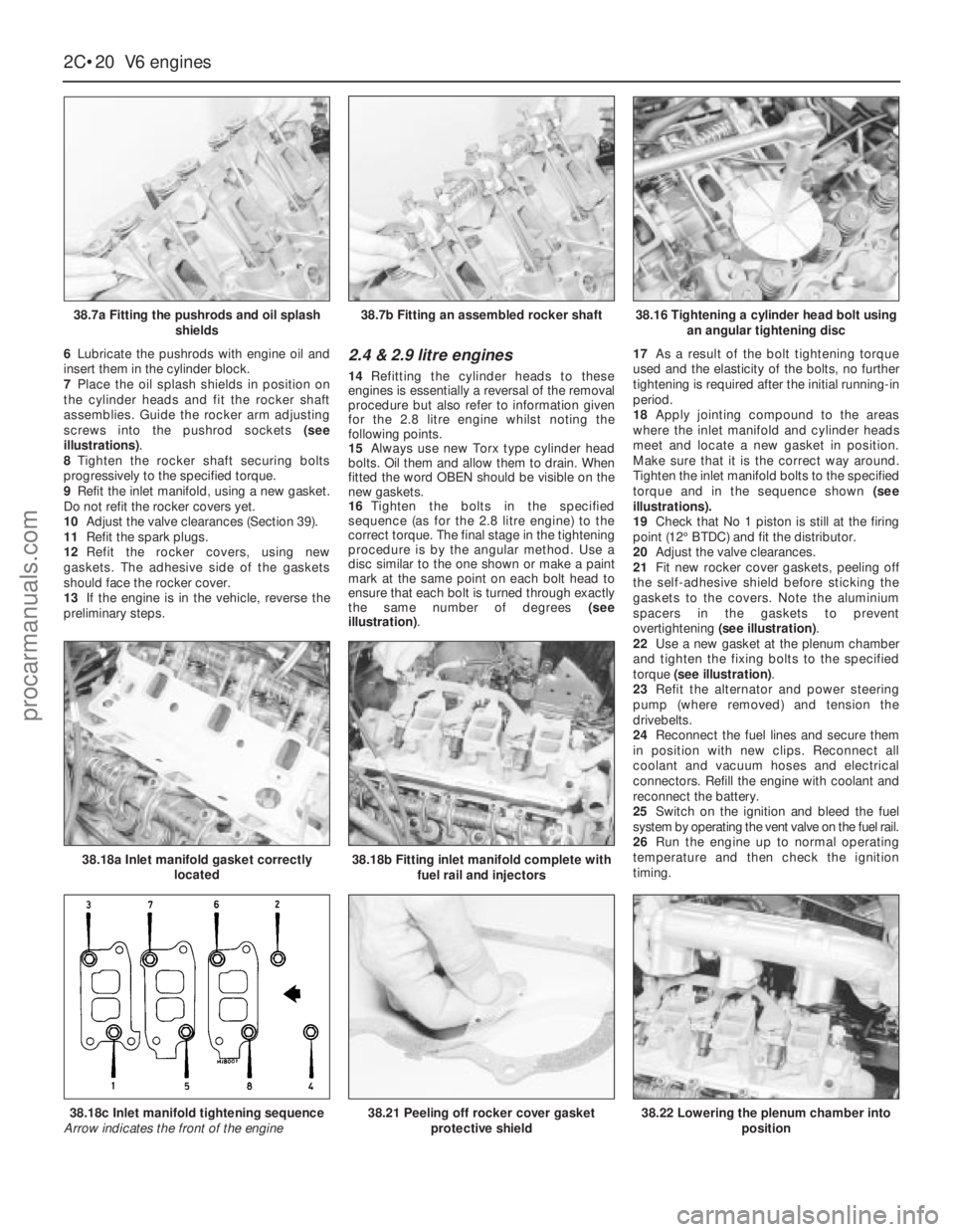
7Place the oil splash shields in position on
the cylinder heads and fit the rocker shaft
assemblies. Guide the rocker arm adjusting
screws into the pushrod sockets (see
illustrations).
8Tighten the rocker shaft securing bolts
progressively to the specified torque.
9Refit the inlet manifold, using a new gasket.
Do not refit the rocker covers yet.
10Adjust the valve clearances (Section 39).
11Refit the spark plugs.
12Refit the rocker covers, using new
gaskets. The adhesive side of the gaskets
should face the rocker cover.
13If the engine is in the vehicle, reverse the
preliminary steps.2.4 & 2.9 litre engines
14Refitting the cylinder heads to these
engines is essentially a reversal of the removal
procedure but also refer to information given
for the 2.8 litre engine whilstnoting the
following points.
15Always use new Torx type cylinder head
bolts. Oil them and allow them to drain. When
fitted the word OBEN should be visible on the
new gaskets.
16Tighten the bolts in the specified
sequence (as for the 2.8 litre engine) to the
correct torque. The final stage in the tightening
procedure is by the angular method. Use a
disc similar to the one shown or make a paint
mark at the same point on each bolt head to
ensure that each bolt is turned through exactly
the same number of degrees (see
illustration).17As a result of the bolt tightening torque
used and the elasticity of the bolts, no further
tightening is required after the initial running-in
period.
18Apply jointing compound to the areas
where the inlet manifold and cylinder heads
meet and locate a new gasket in position.
Make sure that it is the correct way around.
Tighten the inlet manifold bolts to the specified
torque and in the sequence shown (see
illustrations).
19Check that No 1 piston is still at the firing
point (12°BTDC) and fit the distributor.
20Adjust the valve clearances.
21Fit new rocker cover gaskets, peeling off
the self-adhesive shield before sticking the
gaskets to the covers. Note the aluminium
spacers in the gaskets to prevent
overtightening (see illustration).
22Use a new gasket at the plenum chamber
and tighten the fixing bolts to the specified
torque (see illustration).
23Refit the alternator and power steering
pump (where removed) and tension the
drivebelts.
24Reconnect the fuel lines and secure them
in position with new clips. Reconnect all
coolant and vacuum hoses and electrical
connectors. Refill the engine with coolant and
reconnect the battery.
25Switch on the ignition and bleed the fuel
system by operating the vent valve on the fuel rail.
26Run the engine up to normal operating
temperature and then check the ignition
timing.
2C•20V6 engines
38.7a Fitting the pushrods and oil splash
shields
38.18a Inlet manifold gasket correctly
located38.18b Fitting inlet manifold complete with
fuel rail and injectors
38.22 Lowering the plenum chamber into
position38.18c Inlet manifold tightening sequence
Arrow indicates the front of the engine38.21 Peeling off rocker cover gasket
protective shield
38.7b Fitting an assembled rocker shaft38.16 Tightening a cylinder head bolt using
an angular tightening disc
procarmanuals.com