Page 1 of 18
ENGINE LUBRICATION &
COOLING SYSTEMS
i
SECTION LC
CONTENTS
ENGINE LUBRICATION SYSTEM
ENGINE LUBRICATION SYSTEM -Oil Pump
ENGINE LUBRICATION SYSTEM -Oil Pressure Relief Valve
ENGINE LUBRICATION SYSTEM
- Lubricating Oil Passage for Turbocharger
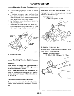
COOLING SYSTEM
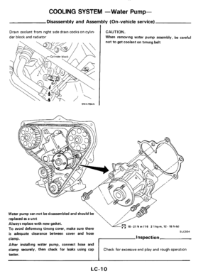
COOLING SYSTEM -Water Pump
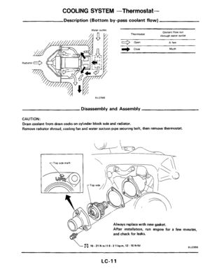
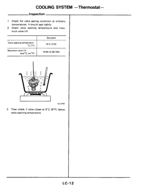
COOLING SYSTEM -Thermostat
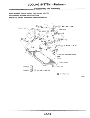
COOLING SYSTEM
- Radiator
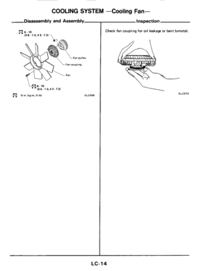
COOLING SYSTEM -Cooling Fan
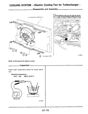
COOLING SYSTEM
- Electric Cooling Fan for Turbocharger
SERVICE DATA AND SPECIFICATIONS
(S D S 1
SPECIAL SERVICE TOOLS
LC- 2
LC- 4
LC- 6
LC- 7
LC- 8
1c-10
1c-11
1c-13
LC- 14
1c-15
1c-16
LC-I 8
Page 2 of 18
ENGINE LUBRICATION SYSTEM
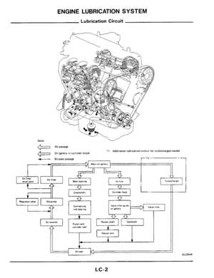
Lubrication Circuit
Note
m 011 parrage
011 gallery in cylinder block '1 Additional lubrication circuit for turbocharged model
f--- By-parr parrage
Maan 011 gallery I--
i
r-il
Crankshaft Cylinder head
Turbocharger
+
--/I--
Valve hfter CO""eCll"g Valve lifier guide rod bearing 011 gallery
+ e -0
Rockerrhaft Camshaft Piiton and cylinder well +
Rocker arm
1
1 011 pan 11
SLC544
LC-2
Page 3 of 18
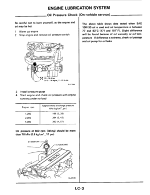
ENGINE LUBRICATION SYSTEM
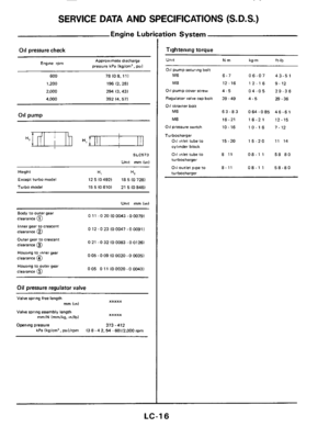
Oil Pressure Check
Be careful not to burn yourself, as the englne and
oil may be hot
1 Warm up engine
2 Stop engine and remove oil pressure switch
SLC545
3 Install pressure gauge
4 Start engine and check oil pressure with engine
running under no-load
Approximate discharge pressure
I kPa (kglcm2, psi1 Engine rpm
1,200 196 (2.281
2,000 294 (3.431
i 4.000 392 (4.571
Oil pressure at 600 rpm (Idling) should be more
than 78 kPa (0.8 kg/cm2, 11 PSI)
ST25051001 4
In-vehicle service)
The above table shows data tested when SAE
1OW-30 oil is used and oil temperature is between
77 and 83°C (171 and 181°F). Slight difference
will
be found because of oil viscosity or oil tem-
perature If difference is extreme, check oil passage
and
oil pump for oil leaks
LC-3
Page 4 of 18
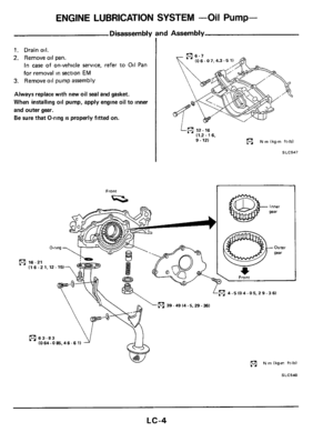
ENGINE LUBRICATION SYSTEM -Oil Pump-
Disassembly and Assembly
1
1. Drain oil.
2. Remove oil pan.
In case of on-vehicle service, refer to Oil Pan
for removal
in section EM
3. Remove oil pump assembly
Always replace with new oil seal and gasket.
When installing
oil pump, apply engine oil to inner
and outer gear.
Be sure that O-ring is properly fitted on.
R
IO 6.07.4.3-5 1
L(nl 12-16 11.2. 16.
9.121 N rn lkg-m ft-lbl
SLC547
Front I
(1 6 -2 1.12-151
R 4.5 I04 -05.2 9 -361
R N rn Ikg-m ft-lbl
SLC548
LC-4
Page 5 of 18
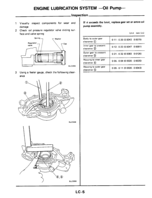
ENGINE LUBRICATION SYSTEM -Oil Pump-
Visually inspect components for wear and
damage
Check
oil pressure regulator valve sliding sur-
face and valve spring
Washer Spr'ng 7
Regulalor, ,/ valve
SLC295
Using a feeler gauge, check the following clear-
ance
SLC550
tion
If it exceeds the limit, replace gear set or entire oil
pump assembly.
Unit rnrn (in)
I 011 -020(00043 000791 Body to outer gear
clearance
(i7
Outer gear to crescent 0 21 - 0 32 (0 0083 0 0126)
LC-5
Page 6 of 18
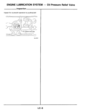
ENGINE LUBRICATION SYSTEM - Oil Pressure Relief Valve
Inspection
1
Inspect for its smooth operation by pushing ball
-- _A
SLC551
LC-6
Page 7 of 18
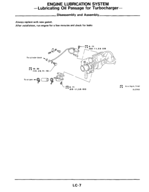
ENGINE LUBRICATION SYSTEM
-Lubricating
Oil Passage for Turbocharger-
Disassembly and Assembly
Always replace with new gasket.
After installation, run engine for
a few minutes and check for leaks
Lm 8-17 108.1 1.58-801
N m (kg-m. ft-lbl
SLC552
LC-7
Page 8 of 18
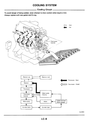
COOLING SYSTEM
Coolicg Circuit
To avoid danger of being scalded, never attempt to drain coolant when engine is hot.
Always replace with new gasket and O-ring.
V
Radlaror
f
+ -
Thermostat
water OuIlet Thermostat
housing
1 Thermostat Open
Thermostat Closed
I intake manifold
(Water parragel Heater
Cylinder block Cylinder head t
SLC553
LC-8