Page 9 of 18

COOLING SYSTEM
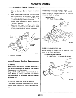
-Changing Engine Coolant
Refer to Changing Engine Coolant in section
MA If the hoses connecting engine and heater
have
been disconnected to dismount heater core
unit and engine. always perform the following
work before filling with engine coolant
Set the heater temperature lever or button to
"Full Hot" position
Disconnect the upper hose from water cock,
and
fill the heater core unit with 500 mP (16.9
US fl 02, 17 6 Imp fl 02) or more of coolant
1
2
DO not remove englne ter
SLC609 v
3 Connect the hoses.
-Checking Cooling Systern-
WARNING:
Never remove the radiator cap when the engine
IS
hot, serious burns could be caused by high pressure
fluid escaping from the radiator
Wrap
a thick cloth around cap and carefully re-
move the cap by turning it a quarter turn to allow
built-up pressure
to escape and then turn the cap
all the way off.
CHECKING COOLING SYSTEM HOSES
Check hoses for proper attachment, leaks, cracks,
damage,
loose connections, chafing and deteriora-
tion
CHECKING COOLING SYSTEM FOR LEAKS
Apply pressure to the cooling system by means of
a tester to check for leakage
Test i ng pressure.
157 kPa (1 6 kg/cm2, 23 psi)
CHECKING RADIATOR CAP
Apply pressure to radiator cap by means of
a cap
tester to see if it is satisfactory
Radiator cap relief pressure:
59 - 98 kPa (0.6 - 1.0 kglcm' , 9 - 14 psi)
" SLC613
LC-9
Page 10 of 18
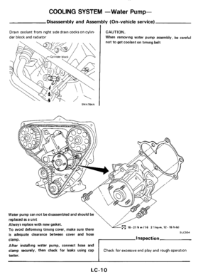
COOLING SYSTEM -Water Pump-
Drain coolant from right side drain cocks on cylin-
der block and radiator CAUTION.
When removing water pump assembly, be careful
16- 21 N m I1 6 2 1 kgm. 12- Eft-lbl Always replace with new gasket.
To avoid deforming timing cover, make sure there
is adequate clearance between cover and hose
clamp.
After installing water pump, connect hose
and
tester.
SLC554
Inspection
end play and rough operation clamp securely, then check for leaks using cap
LC-10
Page 11 of 18
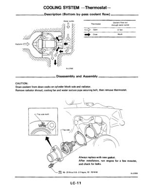
COOLING SYSTEM -Thermostat-
Description (Bottom by-pass coolant flow)
- water OUtkt Coalant flow out
through water Outlet Thermostat
Open A few
r) close Much
SLC565
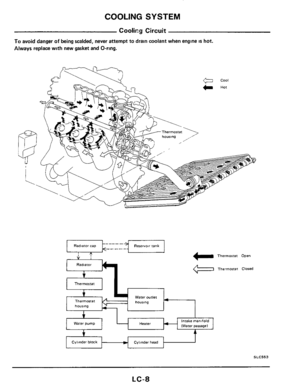
Disassembly and Assembly
CAUTION:
Drain coolant from drain cocks on cylinder block side and radiator.
Remove radiator shroud, cooling fan and water suction pipe securing bolt, then remove thermostat.
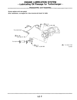
Always replace with new gasket.
After installation. run engine for
a few
and check for leaks. minutes,
SLC555 16.21 N m (1 6.2 1 kg-m, 12.15 ft-lbl
LC-11
Page 12 of 18
COOLING SYSTEM -Thermostat-
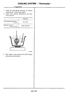
inspection
1 Check for valve seating condition at ordinary
temperatures
It should seat tightly
2 Check valve opening temperature and rnaxl-
mum valve lift
I Standard
76 5 (170) Valve opening temperature
OC (OF)
I 10/90 (0 39/194) Maximum valve lift
mmIoC (dF)
SLC556
3 Then check if valve closes at 5°C (9°F) below
valve opening temperature
LC-12
Page 13 of 18
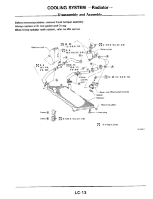
COOLING SYSTEM -Radiator-
Disassembly and Assembly
Before removing radtator, remove front bumper assembly
Always replace with new gasket and O-ring
When filling radiator with coolant, refer to MA section
&em 3.4 10 3.0 4.2 2.2 9) .f' - Water outlet Reservoir tank
Mounting rubber
+Drain plug
Clamp @ 3- 5 IO 3- 0 5.22.3 6)
N rn lkg-m. ft Ibl
SLC557
LC-13
Page 14 of 18
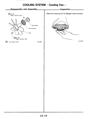
COOLING SYSTEM -Cooling Fan-
-Disassembly and Assembly
(91 6-10
7 (06 - 10.4 3- 7 21
i(916.10 106-1 0.43-72)
(91 N rn lkg-m, ft-lbl SLC558
Inspection
Check fan coupling for oil leakage or bent bimetal.
SLC072
LC-14
Page 15 of 18
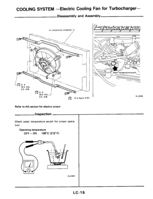
COOLING SYSTEM -Electric Cooling Fan for Turbocharger-
Disassembly and Assembly
7 AW condmoner condenser
Refer to HA section for electric circwt
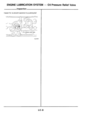
Inspection
Check water temperature switch for proper opera-
tion
Operating temperature
OFF + ON 100°C (212°F)
I I
I
SLC559
LC-15
Page 16 of 18

Engine Lubri
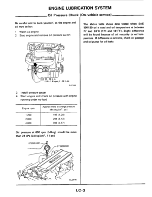
Oil pressure check
Engine rpm Approximate discharge
Dresure kPa
Ikdcm’, DII)
600 78 (0 8,ll I
1,200 196 (2,281
2,000 294 (3,431
4.")
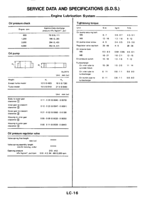
SERVICE DATA AND SPECIFICATIONS (S.D.S.)
Engine Lubri
Oil pressure check
Engine rpm Approximate discharge
Dresure kPa
Ikdcm’, DII)
600 78 (0 8,ll I
1,200 196 (2,281
2,000 294 (3,431
4.000 392 14.571
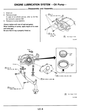
011 pump
SLC573
Unit mm Inn1
Height H, H*
Except turbo model 18 5 IO 7281
Turbo model 15 5 IO 6101 21 5 (0 846)
12 5 IO 4921
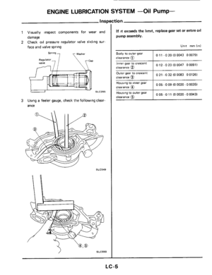
Unit mm lml
0 11 -0 20 IO 0043 -0 0079) Body to Outer gear
clearance @
inner gear to CreKent clearance @
Outer gear to crescent
clearance
@
Housing to mnergear
0 12 -0 23 10 0047 -0 00911
0 21 -0 32 (0 0083 -0 01261
005-009 100020-000351 Clearance 0
0 05 0 11 (0 0020 - 0 0043) Housing to outer gear
clearance
@
Oil pressure regulator valve
Valve spring free length xxxxx mm On1
Valve spring assembly length
Opening pressure
373.412
xxxxx mm/N lmm/kg, dlbl
kPa Ikglcrn’. Pril/rpm 13 8.4 2. 54 - 601/2,000 rpm
tion System
Tightening torque
Unlt Nm kg-m it-lb
011 Pumpsecuring bolt M6
M8
011 pump cover screw
Regulator
valve cap bolt
081 strainer bolt
M6
M8
011 pressure switch
Turbocharger
Oil inlet tube to
cylinder block
011 inlet tube to turbocharger
011 outlet pipe to
turbochar~er
6-7
12.16
4-5
39 -49
63-83
16-21
10
- 16
15-20
8 11
8-11
06-07
12-16
04-05
4-5
0 64 -0 85
16-2
1
10-16
15-20
08-1 1
08-1 1
43-51
9-12 29-36
29-36
46-61
12-15
7-12
11 14
58 80
58-80
LC-16


- water OUtkt Coalant flow out
through water Outlet Thermostat
Open A few
r) close Much
SLC565
Disassembly and Assembly
C")


(91 N rn lkg-m, ft-lbl SLC558
Inspection
Check fan coupling for oil leakage or bent")
