Page 1 of 116

ELECTRICAL SYSTEM
I
SECTION EL
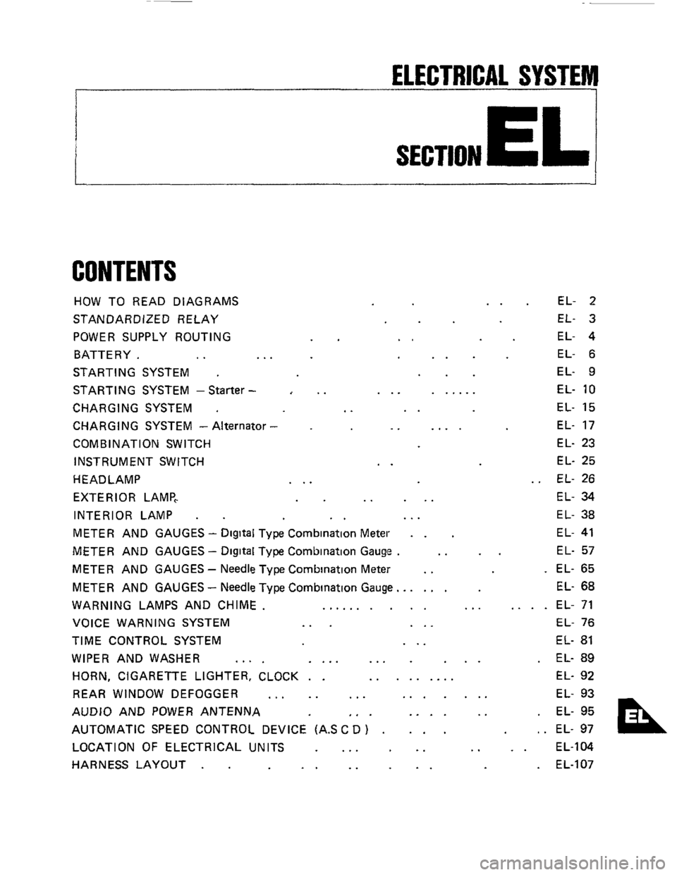
CONTENTS
HOW TO READ DIAGRAMS
STANDARDIZED RELAY
POWER SUPPLY ROUTING
BATTERY.
.. ..
STARTING SYSTEM .
STARTING SYSTEM -Starter -
CHARGING SYSTEM .
CHARGING SYSTEM - Alternator
COMB IN AT1 ON SWITCH
INSTRUMENT SWITCH
HEADLAMP
EXTERIOR LAMP,
INTERIOR LAMP
.
..
..
..
..
..
... ......
..
.. ....
..
.. ...
EL- 2
EL- 3
EL- 4
EL- 6
EL- 9
EL-
10
EL- 15
EL- 17
EL- 23
EL- 25
EL- 26
EL- 34
EL- 38
METER AND GAUGES - Digital Type Combination Meter . . EL- 41
METER AND GAUGES - Digital Type Combination Gauge . .. .. EL- 57
METER AND GAUGES - Needle Type Combination Meter .. . EL- 65
METER AND GAUGES
- Needle Type Combination Gauge.. .... EL- 68
WARNING LAMPS AND CHIME. .......... ... .... EL- 71
VOICE WARNING SYSTEM
... ... EL- 76
TIME CONTROL SYSTEM ... EL- 81
WIPER AND WASHER .... .... ... ... . EL- 89
HORN, CIGARETTE LIGHTER, CLOCK . . ......... EL- 92
REAR WINDOW DEFOGGER
... .. ... ....... EL- 93
AUDIO AND POWER ANTENNA
,. . .... .. . EL- 95
AUTOMATIC SPEED CONTROL DEVICE (AS
C D ) . ... , . EL- 97
LOCATION OF ELECTRICAL UNITS
... .. .. .. EL-104
HARNESS LAYOUT
. . .. .. .. . EL-107
Page 65 of 116
METER AND GAUGES -Needle Type Combination Meter
Combination Meter
pj
0, SENSO
35 36 31
1 TACHO-
METER
BBpgBW *Em 8EAR
FUEL BELT DOOR BRAKE CHARGE OIL RADIATO HEAD- STOP&
COOLANl LAMP TAIL LAMP
0 32 -- a: "E NATION 30
ILLUMI-
0 33 -U 18 19 20 s;14 15 5 23
24 2. 29 1 3 4 11
SEL690D
EL-65
Page 66 of 116
METER AND GAUGES -Needle Type Combination Meter
Tacho, Fuel and Water Temperature Gauges/Wiring Diagram
C z >= oc
:E
I
6$ m
L
m
_I
I I
Y - m -
llllllI
1:
I
I1 I01 I I I IIIIIIII
r-
SELSSlD
EL-66
Page 67 of 116
METER AND GAUGES -Needle Type Combination Meter
Ohmmeter
terminal
,+) , ~-, 1 Float position
Fuel Tank Gauge Check
For removal, refer to FE section
Resistance value
Full
00 EmpN
112
Approx 652
Approx 8052
Approx 30 - 3552
More than 6052
Less than 652
Main gauge
Sub gauge
SEL6750
SEL67SD
,-Speed Sensor Signal Check
Speed sensor is built into the speedometer
Turn speedometer slowly using small screw-
driver, and check continuity of speed sensor
circuit
Continuity exists two times for each turn . 0 K.
SEL696D
--Speedometer Cable Removal -
Press to
L? connect
SEL692D
EL-67
Page 68 of 116
METER AND GAUGES -Needle Type Combination Gauge
Combination Gauge
I
2
P I To boost sensor
z c
+ 0 i m 0
Y
-
b 4
SEL693D
EL-68
Page 70 of 116
METER AND GAUGES -Needle Type Combination Gauge
Oil Temp. Sensor Check
1 Warm up engine
2
3
Stop engine and turn ignition switch OFF
Check resistance of
oil temp sensor
SEL695D
- Boost Gauge Trimmer Adjustment -
When boost gauge does not give proper reading,
adjust
0 kPa (0 mmHg, 0 inHg) point with the
trimmer located on interlor upper wall of glove
box
Use a screwdriver to adjust trimmer
For checking oil pressure sensor and boost
sensor, refer to pages EL-53 and 56
EL-70
Page 100 of 116
AUTOMATIC SPEED CONTROL DEVICE (A.S.C. D.)
Trouble-shooting (Cont'd)
Turn ignition switch to "OFF"
Disconnect speedometer cable from trans-
mission
Connect an ohmmeter between
@ and
Slowly turn speedometer cable pinion by
hand to make
sure ohmmeter pointer
deflects
Ohmmeter pointer deflects twice per
rotation
of pinion.
0.
Check from harness side
Ohmmeter SEL7630
i
Check speed sensor circuit
(Digital type combination meter) -
(Refer to "METER AND GAUGES
- Needle Type Combination Meter"
~~~l~~~ AS c D
control unit
Check harness between A S C D
control unit and speed sensor
signal output terminal
of
combination meter
Does speedometer operate properly?
Go to "Speed Sensor Signal Check"
for checking combination meter
(Refer to "METER AND GAUGES
- Digital Type Combination Meter" )
Replace
speed sensor Check harness between AS C D
control unit and speed sensor
signal output terminal of
combination meter
EL-I 00