Page 2 of 99
DESCRIPTION OF E4N71B
I
The Model E4N71B automatic transmission is the
latest addition to Niaan's lineup
of transmissions.
This transmission
is based on the model L4N71B
(mounted on the 1983 model 810), and can pro-
vide lockup of
all forward speeds (1st to 4th speed)
by electronic control.
By use of a microcomputer, the electronic-control-
led lockup system permits lockup of
all forward
speeds (1st to 4th speed)
Either shifting pattern ("standard" or "power")
is
automatically selected by programs set in the
lockup control unit depending on the speed
at
which the accelerator pedal is depressed These
programs are
set in response to the vehicle speed
and throttle position
rlnhibitor switch \Lockup control unit
/;?\I!
LPower Shift switch and mdtcator
Stop lamp rwlrch
\Kickdown switch
Downshift solenoid
Shift switch and low temperature sensor
Throttle valve rwitchl 0 indicator
Lockup solenoid 0 D cancel solenoid
SAT7M
AT-2
Page 4 of 99

GENERAL SERVICE NOTICE
Repai
Before proceeding with disassembly, thorough-
ly clean the outside of the transmission It IS
important to prevent the internal parts of the
transmission from becoming contaminated by
dirt or other foreign matter.
Disassembly should
be done in a clean work
area. Use
a nylon cloth or paper towel for wiping
parts clean. Common
shop rags can leave lint
that might interfere with the transmission's
operation.
When disassembling parts, be sure to place
them in order
in parts rack so they can be put
back in the unit
in their proper positions
All parts should be carefully cleaned with a
general purpose, non.flammable solvent before
inspection or reassembly.
Gaskets,
seals, and O-rings should be replaced.
It is also very important to perform functional
tests whenever it is designated.
The valve body contains many precision parts
Contri
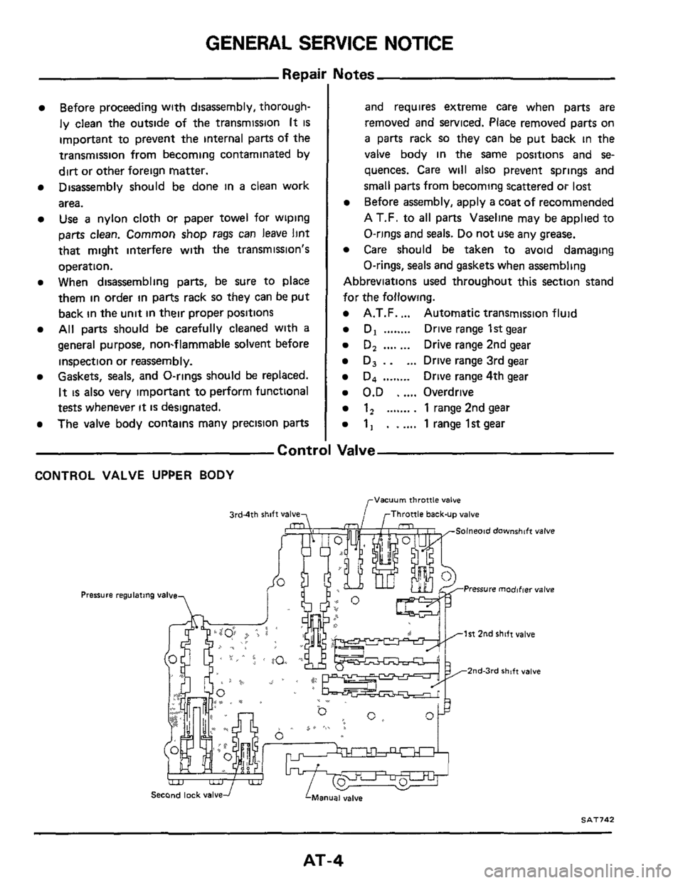
CONTROL VALVE UPPER BODY
3rd4th shift valve7
Pressure I
Uotes
and requires extreme care when parts are
removed and serviced. Place removed parts on
a parts rack so they can be put back in the
valve body in the same positions and
se-
quences. Care will also prevent springs and
small parts from becoming scattered or
lost
Before assembly, apply a coat of recommended
A
T.F. to all parts Vaseline may be applied to
O-rings and
seals. Do not use any grease.
Care should be taken to avoid damaging
O-rings, seals and
gaskets when assembling
Abbreviations used throughout this section stand
for the following.
A.T.F. ... Automatic transmission fluid
D, ........ Drive range 1st gear
D, .... ... Drive range 2nd gear
D, . . ... Drive range 3rd gear
D4 ........ Drive range 4th gear
0.D . .... Overdrive
1, ....... . 1 range 2nd gear
1, . . .... 1 range lstgear
Valve
Vacuum throttle valve
f rThrottle back-up valve
1st 2nd shift valve
2nd3rd shift valve
Second lock valve -i
SAT742
AT-4
Page 5 of 99
GENERAL SERVICE NOTICE
Control Valve (Cont'd)
CONTROL VALVE LOWER BODY
3rd-2nd timing valve
f --
, /
-7, - _- _:. - A=----* --
-
SAT705
Lock-up Control Valve and O.D. Cancel Valve
Retaining pin1
SAT498
AT-5
Page 7 of 99
GENERAL SERVICE NOTICE
I (Cont'd) Oil Cham
OIL CHANNELS IN DRUM SUPPORT OIL CHANNELS IN CONVERTER HOUSING
To lock-up ~ontrol valve
rDrain (E4N71Bl
clutch (Front)
Forward clutch
clutch pressure Front & 0 0 lubrmtmn
SAT706
3peration Mechanic:
In the E4N71B and 4N71B automatic transmission, each part operates as shown in the following table at
each gear select position
'arking
pawl
Htgh-
'everse
Front) Forward clutch (Rear) 0 D band servo Direct
clutch Range -
Release
ON ON
1 Reverse 1 ON 1 ION) ON
+-
ON I
I Neutral I ON I (ON) ON
T-
ON
-
ON
-
ON
ON
JT
I ION
'34
(0 D 1 ON I ON
Second I ON I (ON) ON
1 ON I (ON) 12
(Second) ON ON I ON
ON ord ON I I ON
The low & reverse brake IS applied In "1 I" range to prevent free wheeling when coasting and allows engine braking.
AT-7
Page 13 of 99
ON-VEHICLE SERVICE
-Inhibitor Switch Adjustrnent-
(Cont'd)
3. Loosen the attaching bolts.
4 Using an aligning pin, [2 0 mm (0.079 in) dia 1
move the switch until the pin falls into the hole
in the rotor
5. Tighten the attaching bolts equally.
6. Recheck for continuity. If faulty, replace the
switch.
--Manual Linkage Adjustrnent-
M,we the shift lever from the "P" range to "Range
1"'. You should be able to feel the detents in each
range
If the detents cannot be felt or the pointer indicat-
ing the range
is improperly aligned, the linkage
needs adjustment
1
2 Loosen locknuts
Place shift lever in "N" range.
3. Move range selector lever to the "N" range.
Range selector lever
SAT741
4 Tighten lock nuts when floor control lever IS in
"N" range and pushed against the "P" range
side.
5. Move control lever from "P" range to "1"
range Make sure that control lever can move
smoothly
and without any sliding noise.
AT-I 3
Page 15 of 99
ON-VEHICLE SERVICE
Kickdown Switch Adjustment
When the pedal is fully depressed, a click can be
heard just before the pedal bottoms out
If the
click
is not heard, loosen the locknut and extend
the switch until the pedal lever makes contact with
the switch and the switch clicks
Kickdown switch 7
F$i& Downshift solenold
qi& Downshift solenold
SAT719
Do not allow the switch to make contact too soon.
This would cause the transmission to downshift on
part throttle.
DIAGNOSIS:
Switch can be heard clicking, and the transmission
still does not kickdown:
Check the continuity of the switch.
Also check for
available current.
The vehicle upshifts
at approximately 55 (1st to
2nd) and
90 kmlh (2nd to 3rd) (34 and 56 MPH)
only The kickdown switch may be internally
shorted (When the switch
is shorted, there IS con-
tinuity through the switch in any position).
AT-I 5
Page 18 of 99

REMOVAL AND INSTALLATION
Removal
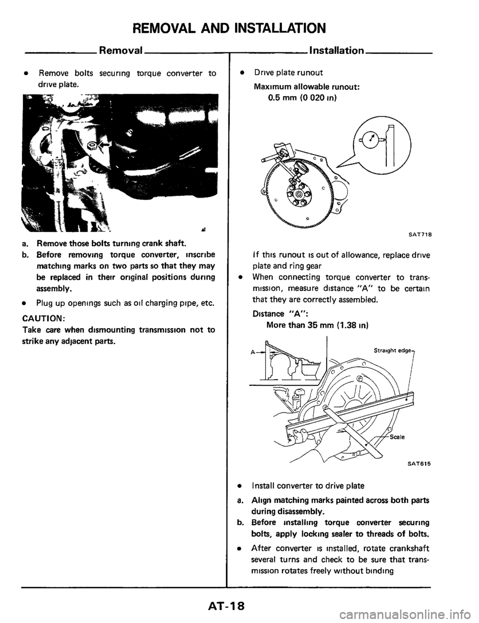
a Remove bolts securing torque converter to
drive plate.
a. Remove those bolts turning crank shaft.
b. Before removing torque converter, inscribe
matching marks on
two parts so that they may
be replaced in their original positions during
assembly.
a Plug up openings such as oil charging pipe, etc.
CAUTl ON :
Take care when dismounting transmission not to
strike any adjacent
parts.
Installation
0
a
a.
b.
a
Drive plate runout
Maximum allowable runout:
0.5 mm (0 020 in)
n
SAT718
If this runout is out of allowance, replace drive
plate and ring gear
When connecting torque converter to trans-
mission, measure distance "A" to be certain
that they are correctly assembled.
Distance "A":
More than
35 mm (1.38 in)
Install converter to drive plate
Align matching marks painted across both parts
during disassembly.
Before installing torque converter securing
bolts, apply locking sealer to threads
of bolts.
After converter is installed, rotate crankshaft
several turns and check to be sure that trans-
mission rotates freely without binding
AT-I 8
Page 20 of 99
MAJOR OVERHAUL
N rn 1kg-m. ft-lb)
@ 39 49140-50.29-361
@ 10- 15110- 15.7-11) @ 44.54 14 5 - 5 5,33 -401
@ 13 18113-1.8.9-13)
011 pump assembly & 5 -7 (05 -07.36.5 1) @ 8- 11 (08- 1.1,58-80)
@ 7 -9 (07 -0 9,5 1 -65)
@I 5 4 - 7 4 10.55 - 0 75,4 0 - 5 4)
@ 5.7 105 -0.7,36 - 5 1) @ 29 39130-40.22-29)
O-ring (E4N71B)'
Converter housing
0 D planetary gear assembly
/
/ Connectmg shell-,
lbp&y ) ,,,rLOck*pcontrol solenotd /~ brakeband , /Thrust washer *-
, /Gasket *
Lathe cut seal Tin& 7
\Thrust washer t
2nd brake band
Drum support
0 D cancel solenold
0 D band brake servo assembly
* Always replace
t Select with proper thcknerr * Adjustment IS requwed
AT-20