Page 50 of 99
ASSEMBLY
1. Install parking rod, manual plate, manual plate
lock nut, parking brake lever and snap rings.
Ob/-- 0 - 0- 7
SAT720
2 Lubricate and install low and reverse piston
into the case.
SATM8
3 Install thrust ring, piston return spring, thrust
washer and oneway clutch inner race.
4. Install hex-head slotted bolts.
Check that return spring is centered on race before
tightening.
AT135
5 Install steel dished plate first, then steel and
friction plates, and, finally, retaining plate and
snap-ring
AT129
AT-50
Page 52 of 99
ASSEMBLY
10. Install connecting drum with sprag by rotating
drum clockwise.
SAT732
11 Check one-way clutch to see if it operates
orooerlv
SAT536
12. Install rear internal gear.
-
SAT054
13. Install snap-ring on shaft.
14 Secure thrust bearing and thrust washer with
vaseline and install rear planetary carrier
SAT055
15 Install rear planetary carrier snap ring.
If you have insufficient space to install snap ring
into drum groove, pull connecting drum forward
as
far as possible.
SAT056 SAT056
AT-52
Page 58 of 99
ASSEMBLY
15 (0 059)
17 (0 067)
19 (0 075)
2 1 (0 083)
2.3 (0 091)
25 (0098)
2 7 (0 106)
Available 0 D thrust washer
3 1528-XO106
31 528-XO105
31528-X0100
31 528-X0101
31 528-XO102
31528-XO103
31 528-XO104
Thickness mm (in) I Part number
Thickness mm (in) Part number
1 2 (0.047)
14 (0 055)
16 (0063)
18
(0071)
20 (0079)
22 (0087)
31556-X0100
3 1556-X0101
31556-X0102
31 556-XO103
31 556.X0104
31 556-XOlO5
26. Adjust 2nd brake band. Tighten piston stem to
the specified value Back off two full turns and
secure with lock nut
SAT580
27. Lubricate O.D. servo O-rings, then install 0 D
band servo, brake band and band strut
7 0 D band %NO
SAT581
28. Lubricate seal ring of drum support, then
install
0 D. bearing & race, O.D. thrust washer
and
O.D. pack on drum support. Make sure
that brake band strut
is correctly installed.
70 D pack
AT-58
Page 59 of 99
ASSEMBLY
29. Adjust O.D. band Tighten piston stem to the
specified value Back off
two full turns and
secure with lock nut.
SAT625
30. Test 0.D band servo operation using corn-
pressed air.
apply pressure
SAT648
31. Install accumulator parts, then secure with
snap ring.
ACCUmUlafOr
Accumulator plug
Snap rmgi
SAT561
32. Lubricate O-ring of oil pump, then install
Before installing oil pump housing and oil pump on
O.D. case, ensure that they have been centered
properly.
Refer to Oil Pump in Repair for Component parts.
33. Remove the two bolts used to temporarily
tighten
O.D. case. Apply sealant to seating
surface
of converter housing around the bolt
holes
needle bearing & race and oil pump
APPIV sealant SAT738
34 Install converter housing on O.D. case and
35. Install input shaft.
tighten to the specified torque
.. SAT585
36. Before installlng valve body assembly perform
a final operation check of all assembled com-
ponents, using compressed air
AT-59
Page 61 of 99
ASSEMBLY
290 (1 142)
29 5 (1 161)
30 0 (1 1811
30 5 (1 201)
31 0 (1 220)
Vacuum diaphragm rod selection
31932-XO103
31932-X0104
31932-XOlOO
31932-X0102
31932-XOlOl
Measured depth
“L” mm (in)
Under 25 55
(1 0059)
25 65
- 26 05
(1
0098 - 1 02561
2615-2655
(1 0295 - 1 04531
26 65.27 05
(1 0492
- 1 0650)
Over 27 15
(1 0689)
Rod length
mm (in) Part number
41 Install vacuum diaphragm.
Make sure that vacuum diaphragm rod does not
interfere with side plate
of control valve.
42 Install downshift solenoid, O.D. cancel sole-
noid, O.D. indicator switch and lock-up sole-
noid.
LO D csncei rolenoid SAT740
43. Install inhibitor switch Check for proper
operation in each range using
a circuit tester.
Refer to On Vehicle Service.
Y li
SAT082
44 Before installing oil pan, check parking pawl
engagement Make wiring connections to shift
switches and low temperature sensor
(E4N71B
automatic transmission models)
45. Install oil pan with new gasket.
-
AT-61
Page 63 of 99

TROUBLE-SHOOTING AND DIAGNOSES
Preliminary Checks
(Prior to Road Testing)
FLUID LEAKAGE
To detect a fluid leak
1) Raise vehicle
2) Clean area suspected of leaking
3) Start engine, apply foot brake, place control
lever in drive, and wait a few minutes
4) Stop engine
5) Check for fresh leakage
FLUID CONDITION
Examine the AT F and note its color, texture,
and odor
1) Dark of Black Fluid
With a burned odor
- Worn friction material
2) Milky Pink Fluid Water Contamination
- Road water entering through filler
tube or breather
3) Varnished Fluid, light to dark brown and
tacky Oxidation
- Over or Underfilling
- Overheating
- Road Testing
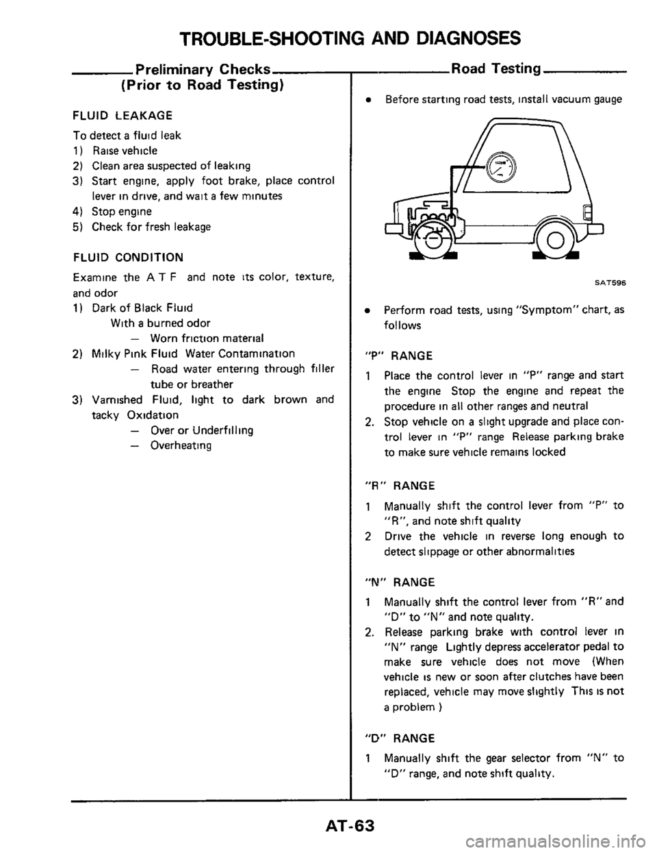
Before starting road tests, install vacuum gauge
SAT596
Perform road tests, using "Symptom" chart, as
follows
"P" RANGE
1 Place the control lever in "P" range and start
the engine Stop the engine and repeat the
procedure in all other ranges and neutral
2. Stop vehicle on a slight upgrade and place con-
trol lever
in "P" range Release parking brake
to make sure vehicle remains locked
"R" RANGE
1 Manually shift the control lever from "P" to
"R", and note shift quality
2 Drive the vehicle in reverse long enough to
detect slippage or other abnormalities
"M" RANGE
1 Manually shift the control lever from "R" and
"D"
to "N" and note quality.
2. Release parking brake with control lever in
"N" range Lightly depress accelerator pedal to
make sure vehicle does not move (When
vehicle
is new or soon after clutches have been
replaced, vehicle may move slightly This
IS not
a problem )
"D" RANGE
1 Manually shift the gear selector from "N" to
"D" range, and note shift quality.
-
AT-63
Page 65 of 99

TROUBLE-SHOOTING AND DIAGNOSES
Vehicle speed
Gearshift krn/h (MPH)
Road Testing (Cont'd)
I
Propeller shaft Line pressure
revolution rprn kPa (kg/cm2, psi)
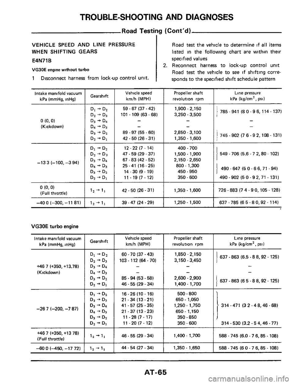
VEHICLE SPEED AND LINE PRESSURE
WHEN SHIFTING GEARS
E4N71B
VG3OE engine without turbo
1 Disconnect harness from lock-up control unit.
D4 +D3
D3 + D2
Dz + Di
Road test the vehicle to determine if all items
listed in the following chart are within their
specified values
2. Reconnect harness to lock-up control unit
Road test the vehicle to
see if shifting corre-
sponds to the specified
shift schedule pattern
490.647 (5 0- 66,71.94)
490 -902 (5
0 -92,71 - 131)
25.41 (16.25) 800 .1,300
14 .30 (9 - 19)
11
- 19 (7- 12)
450.950
350.600
Intake manifold vacuum
kPa (mrnHg, inHg)
I 1 785 - 941 (8 0.9 6, 114.137) DI+D2 1 59-67(37-42)
Dz + Da
1,900 - 2,150
3,250
- 3,500 101 . 109 (63 - 68) I
0 (0.0)
(Kickdown) ~-
1 745-902(76-92.108-131) 03 +& I 89 - 97 (55 - 60) 2,850 - 3,100
D2
+ Di 42.50 (26 -31) 1,350 - 1,600
12.22 (7. 14)
47 .59 (29 - 37)
67 .83 (42 - 52)
549.706 (5.6 - 7 2.80 - 102)
400 - 700
1,500
- 1,900
2.150.2.650
-13 3 (-100, -3 94)
0 (0.0)
(Full throttle) I 42-50(26-31) I 1,350.1,600 I 726 -883 (7 4.90,105 - 128) 12 + 11
-40 0 (-300, -1 1 81) 12+11 I 39-47(24-29) I 1,250-1.500 I 637-785(65-80.92-114)
VG30E turbo engine
Intake manifold vacuum
kPa (mmHg, inHg) Gearshift Vehicle speed
km/h (MPH)
60 - 70 I37 - 43)
103
- 112 (64 - 70)
-
-
85 - 94 (53 - 58)
46
- 55 (29 - 34)
Propeller shaft
revolution rpm
1,850.2.150
3,150
- 3,450
-
-
-
2,600 - 2,900
1.400- 1,700
Line pressure
kPa (kg/crnz, psi1
1 637.863 (6.5 - 8 8,92 - 125)
-
-
1 637.863 (6 5 - 8 8,92. 125)
+46 7 (+350, +13.78)
(Kickdown)
500.800
650
- 1,050
1,250
- 1,750
650
- 1,150
350 - 850
350.600
1,400
. 1,700
-
16-26(10-16)
21-34(13-21)
41
- 57 (25.35)
21-37(13-23) 1
1 - 28 (7 - 17)
11
- 20 (7 - 12)
46.55 (29 - 34)
314 -471 (3 2 -48.46-68)
314 - 530 (3.2.5 4.46.77)
-26 7 (-200, -7 87)
+46 7 (+350, +13 78)
(Full throttle) 588 - 745 (6.0.7 6,85 - 108)
-60 0 (-450. -17 72) 44 - 54 (27 - 34) 1,350 - 1,650 588 - 745 (6 0 - 7 6.85 - 108)
AT-65
Page 66 of 99
TROUBLE-SHOOTING AND DIAGNOSES
Road Testing (Cont'd)
SHIFT SCHEDULE
VG30E engine without turbo
[Standard pattern]
Upshift
: I
7
I
I
. Lock-up zone
-_.
10 20 30 40 50 60 70 80 90 100 110 1M 130 19 150 160 l?O 180
110) (20) (30) 1401 150) (60) 170) 180) 190) 11001 111Ol
Vehicle speed kmlh IMPH)
Downshift
i
I 018
10 20 30 40 50 60 70 80 90 100 110 120 130 140 170 160 170 180
1101 120) 1301 140) 150) 160) 1701 18b) I&) (100) ciior
Vehicle speed kmlh 1MPH)
SAT746
SAT745
AT-66