Page 91 of 99

TROUBLE-SHOOTING AND DIAGNOSES
Pressure Testing ~ ~~
2
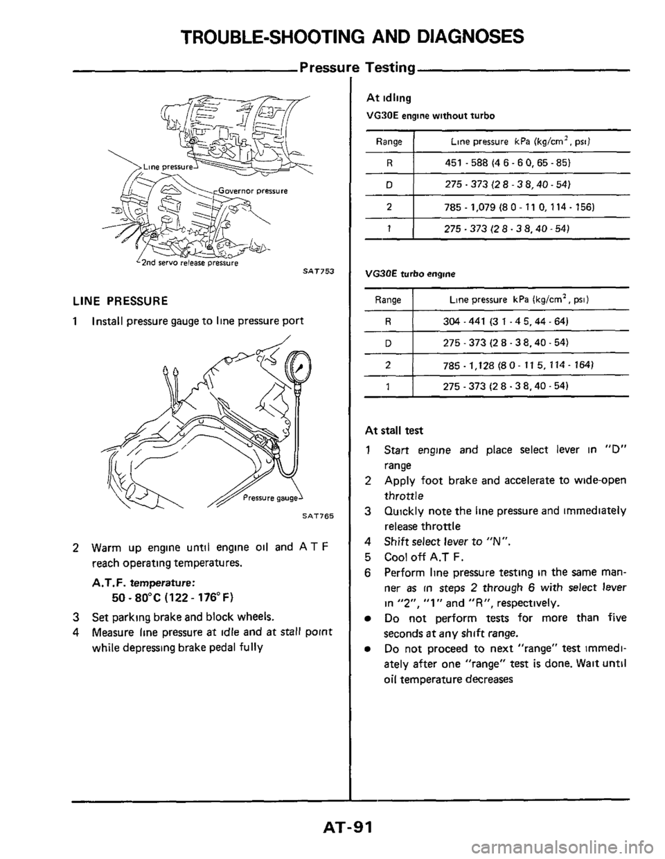
LINE PRESSURE
1 Install
pressure gauge to line pressure port
785 - 1,128 (8 0- 11 5, 114- 164)
SAT765
1
2 Warm up engine until engine oil and AT F
reach operating temperatures.
A.T.F. temperature:
3 Set parking brake and block wheels.
4 Measure line pressure at idle and at stall point
while depressing brake pedal
fully
50 ~ 80°C (122 - 176°F)
275 - 373 (2 8.3 8.40.54)
At idling
VG90E engine without turbo
Range 1 Line pressure kPa (kg/crn2. psi)
R I 451 -588(46-60,65-85)
D 1 275-373(28-38.40-54)
2 I 785.1,079 (80- 11 0,114- 156)
1 1 275-373(28-38.40-54)
VG3OE turbo engine
Range Line pressure kPa (kg/cm2, psi)
304-441 (31-45.44-64)
275
- 373 (2 8.38.40.54)
At stall test
1 Start engine and place select lever in "D"
range
2 Apply foot brake and accelerate to wide-open
throttle
3 Quickly note the line pressure and immediately
release throttle
4 Shift select lever to "N".
5 Cool off A.T F.
6 Perform line pressure testing in the same man-
ner as in steps 2 through 6 with select lever
in
"2". "1" and "R", respectively.
Do not perform tests for more than five
seconds
at any shift range.
Do not proceed to next "range" test imrnedi-
ately after one "range"
test is done. Wait until
oil temperature decreases
AT-91
Page 93 of 99

TROUBLE-SHOOTING AND DIAGNOSES
Stall
The stall test is an effective method of testing
clutch and band holding ability, torque converter
one-way clutch operation, and engine performance
A
stall test should only be performed as a last
resort because of the high fluid temperature it
generates and the excessive load it places on the
engine and transmission.
CAUTION:
a. Transmission and engine fluid levels should
b
c.
d
always be checked and fluid added as needed.
Run engine to
attain proper warm-up.
During test, never
hold throttle wide-open for
more than
5 seconds
Do not test more than two gear ranges without
driving vehicle to
cool off engine and trans-
mission
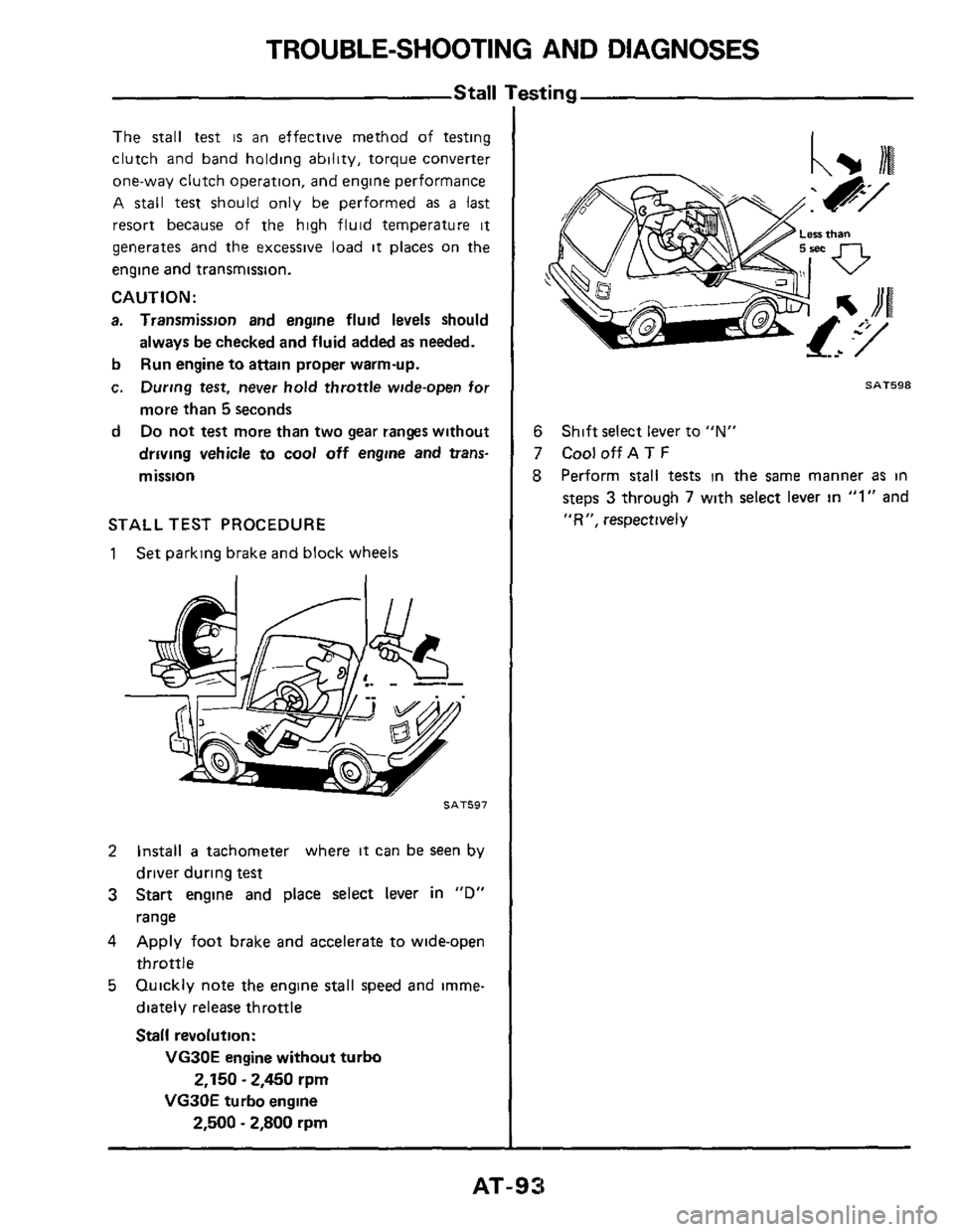
STALL TEST PROCEDURE
1 Set parking brake and block wheels
SAT597
2 Install a tachometer where it can be seen by
driver during
test
3 Start engine and place select lever in "D"
range
4 Apply foot brake and accelerate to wide-open
throttle
5 Quickly note the engine stall speed and imme-
diately release throttle
Stall revolution:
VG30E engine without turbo
VG30E turbo engine
2,150 - 2,450 rpm
2,500 - 2,800 rpm
SAT598
6
7 CooloffAT F
8 Perform stall tests in the same manner as in
steps 3 through 7 with select lever in "1" and
"R", respectively
Shift select lever to "N"
AT-93
Page 94 of 99
TROUBLE-SHOOTING AND DIAGNOSES
STALL TEST ANALYSIS
“D range test
NG OK
Stall revolution is
I
1 Too low 4 1 Too high Lock-up clutch is dragging,
converter one-way clutch
is
engine is not performing
properly
4 Direct clutch, forward
clutch (Rear) or one-way
clutch slips damaged (shpping), or
Lock-up clutch is dragging.
convener one-way clutch
is
engine is not performing
properly
I High-reverse clutch
(Front) or low
& rev
brake slips damaged (slipping), or
whether high-reverse clutch
(Front) or low &rev brake
OK NG
One-way Direct clutch or
clutch slips forward clutch
(Rear) slips
When shift select lever IS
In “1” range
OK
No engine braking Effective engine (Rear) slips slips
braking
I
High-reverse
clutch (Front)
slips
Low & rev brake
slips
If converter one-way clutch is frozen, vehicle will have poor high speed performance. If converter one-way
clutch
is slipping, vehlcle will be sluggish up to 50 or 60 kmlh (30 or 40 MPH)
AT-94
Page 98 of 99

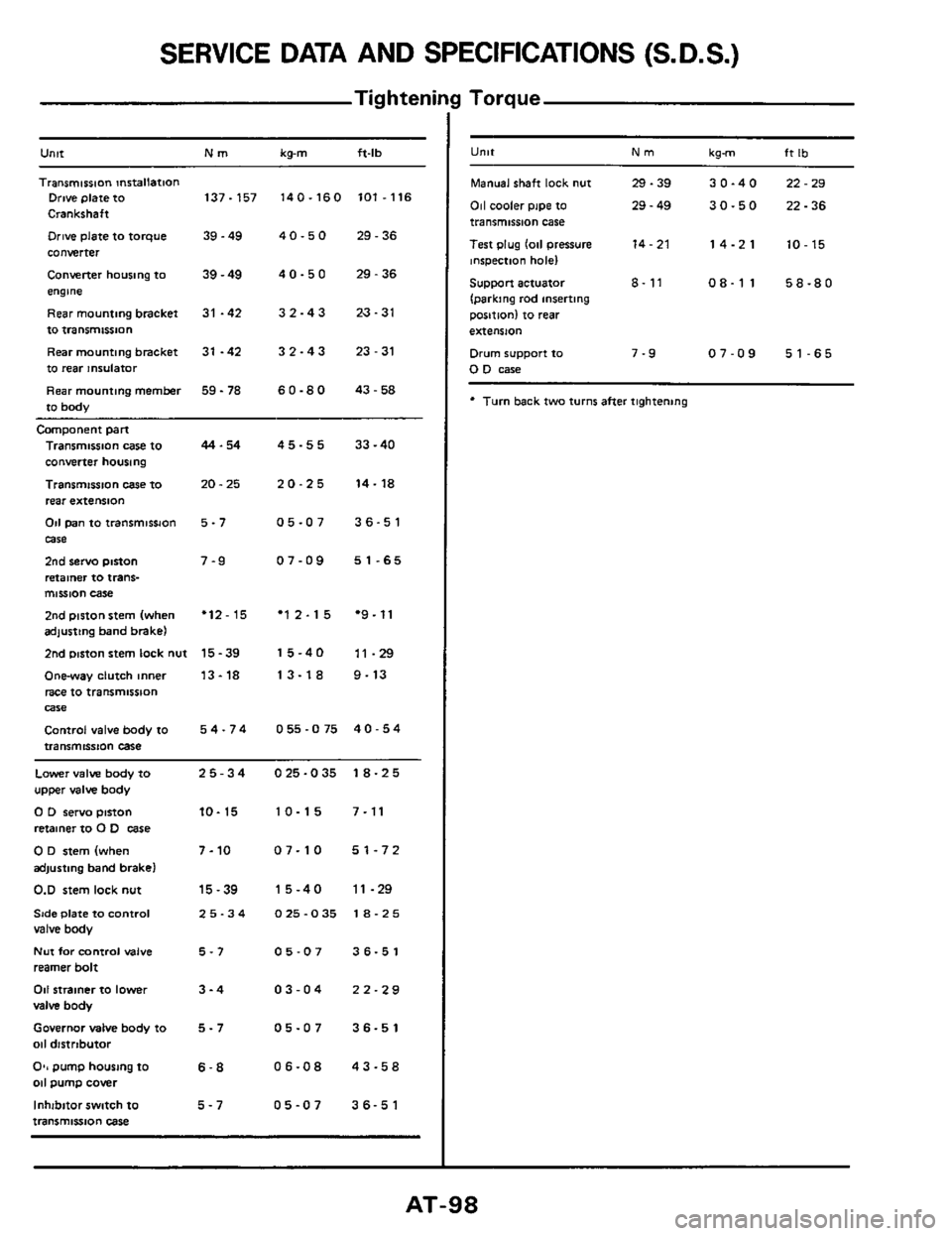
SERVICE DATA AND SPECIFICATIONS (S.D.S.)
Tig hteni
Untt Nm kg-m ft-lb
Transmission mrtallation Drive plate to 137-157 140-160 101.116
Crankshaft
Drive plate to torque 39.49 4 0.5 0 29.36
converter
Converter housing to
39 - 49 4 0 - 5 0 29 - 36
engme
Rearmountingbracket
31 -42 32-43 23-31
to transmissnon
Rear mounting bracket
31 -42 3 2 - 4 3 23 - 31
to rear insulator
Rear mounting
member 59 - 78 6 0.8 0 43.58
to body
Camponent part
Transmission case to
converter housing
Transmission
case IO
rear extension
Od pan to transmissJon
case
2nd servo piston
retainer to trans- mission case
2nd piston stem (when adjusting band brake)
2nd mston stem lock nut
Onway clutch inner
race to transmission
Control valve body to
transmission case
Wle
44.54
20.25
5-7
7-9
'12-15
15-39
13-18
54-74
45-55 33-40
20-25 14-18
05-07 36-51
07-09 51-65
'12-15 *9.11
15-40 11-29
13-18 9-13
055-075 40-54
Lower valve body to 25-34 025-035 18-25
upper valve body
0 D servo pinon 10- 15 10-15 7-11
retainer to 0 D case
0 D stem (when 7-10 07-10 51-72
adjusting band brake)
0.D stem lock nut 15-39 15-40 11-29
Side Plate to Control 25-34 025-035 18-25 valve body
Nut for control valve 5-7 05-07 36-51
reamer bolt
011 strainer to lower 3-4 03-04 22-29
valve body
Governor MIM body to 5 - 7 05-07 36-51
011 distrtbutor
O*, pump housing to 6-8 06-08 43-58 011 pump cover
Inhibitor switch
to 5-7 05-07 36-51
transmission case
I Torque
U"lt Nm kgm ft Ib
Manual shaft lock nut 29.39 30-40 22-29
011 cooler pipe to 29 - 49 30-50 22-36 transmission case
Test plug
lo11 pressure 14-21 14-21 10-15 inspection hole)
Support actuator 8- 11 08-11 58-80
(parking rod inserting
position) to
rear
extension
Drum support to 7-9 07-09 51-65 0 D case
* Turn back two turns after tightening