Page 22 of 99
DISASSEMBLY
1. Remove torque converter, drain A.T.F
through end of
rear extension, and place trans-
mission on
Tool.
v
SAT520
2 Remove lock-up solenoid (E4N71B).
3. Remove converter housing.
SATOW
4. Remove oil pan and inspect its contents. An
analysis of any foreign matter can indicate the
types of problems to look for. If the fluid
IS
very dark, smells burned, or contains foreign
particles, the frictional material (clutches,
band.) may need replacement. A tacky film
that will not wipe clean indicates varnish bulld
up which can cause valves, servo, and clutches
to stick and may inhibit pump pressure.
SAT006
5. Loosen 2nd band servo piston stem lock nut
and tighten piston stem.
If it turns more than
two turns, the band
is worn out.
SAT71 5
AT-22
Page 27 of 99
DISASSEMBLY
27 Remove rear extension.
Be careful not to lose retainer washer.
rWarher
SAT537
2% Remove output shaft with governor.
11 SAT019
29. Remove governor thrust washer and needle
bearing.
Remove one-way clutch inner race attaching
hex-head slotted bolts using
Tool
30. Remove one-way clutch inner race, return
thrust washer, low and reverse return spring,
and spring thrust ring.
31. ,Apply air pressure to remove low and reverse
brake piston
. ' SAT022
32. Remove snap ring, then remove lock nut,
manual plate and parking rod.
y- - " -
SAT720
33 Remove Inhibitor switch and manual shah.
34. Remove
O.D. indicator switch and O-ring.
AT-27
Page 28 of 99
REPAIR FOR COMPONENT PARTS
Oil Pump
011 pump inner gear,
pump =Over
1
011 pump housing
Lathe cur seal
011 seal
l
Lock-up control valve
DISASSEMBLY
1 Remove pump cover from pump housing
2. Stake off retaining pin using a punch [outer
dia.
1.5 to 1.8 mm (0.059 to 0.071 in)], then
remove lock-up control valve and spring
B
SAT721
SAT722
INSPECTION
1. Inspect pump body, bushing and pump shaft,
for
wear.
2. Inspect gears, lock up control valve, spring and
all internal surfaces for damage and visible
wear.
AT-28
Page 29 of 99
REPAIR FOR COMPONENT PARTS
No of
active coil
Outer
coil dia
rnrn (in)
Wire dia
rnrn (in) Valve spring
Oil Pump (Cont’d)
Valve spring chart
Installed
Length
rnrn (in) N (kg. Ib)
Free length
rnrn (in)
Lock-up control valve 10 89 0 65 (0 02561 5 45 (0 21461 14 5 25 7 (1 0121 16 0 (0 630) (1 11, 45)
3 Measure clearance between outer gear and
crescent.
Standard clearance:
Wear limit:
0.14 - 0.21 mm (0.0055 - 0.0083 in)
0.25
mm (0.0098 in)
4 Measure clearance between outer gear and
pump housing.
Standard clearance:
Wear limit:
0.05 - 0.20 mm (0.0020 - 0.0079 in)
0.25
mm (0.0098 in)
5
SAT026
Using a feeler gauge and straight edge, measure
clearance between
gears and pump cover
Standard clearance:
0.02
- 0.04 mm (0.0008 - 0.0016 in)
Wear limit:
0.08 mm (0.0031 in)
AT162
AT-29
Page 30 of 99
REPAIR FOR COMPONENT PARTS
Oil Pump (Cont'd)
ASSEMBLY
1. Install lock-up control valve and spring into oil
pump cover, then tap new retaining pin.
2 Mount pump housing in Tool and suitable
spacer. Set up pump housing with inner and
outer pump gears on
it and install pump cover
to pump housing Temporarily assemble
oil
pump.
sar-0
3 Set the cover to within the run-out of the
specified total indicator reading.
Total indicator reading:
Less than 0.07 mm (0 0028 in)
SAT541 &25580001
4 Tighten pump securing bolts to the specified
torque Recheck run-out
Drum Support
DISASSEMBLY
1 Remove drum support and gasket from O.D.
case.
SATW
2. Stake off retaining pin using a punch [outer
dia.
1.5 to 1.8 mm (0.059 to 0.071 in)], then
remove
O.D. cancel valve and spring
Don't stake it off from contacting face side
7 Retaining pin
00
AT-30
Page 35 of 99

REPAIR FOR COMPONENT PARTS
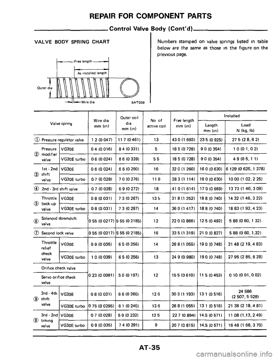
Control Valve Body (Cont'd)
I
@ Second lock valve
VALVE BODY SPRING CHART
055(00217) 555(021851 16 33 5 (1 319) 21 0 (0 827) 5 88 (0 60,1.32)
Free length
check
valve VG30E turbo 1 0 (0 0391 6 5 (0 256) 13 24 9 (0 980)
Outer
19 0 (0 748) 27 95 (2 85,6 28)
Numbers stamped on valve springs listed in table
~ below are the Same as those in the figure on the
previous page.
Orifice check valve
Servo orifice check
valve
3rd - 4th VG30E
@ shift
VG30E turbo
I nsta I led Outer coil
mm (in)
Wire dia No of Free length
Valve spring dia active
coil mm (in) Length mm (in)
mm (in) N (kg. Ib)
023 (00091) 50 (0 197) 12
0 8 (0 031) 6 6 (0260) 12 6
0 75 (0 0295) 6 1 (0 240) 13 6
-
Solenoid downshift 10 55 (0 0217) 15 55 (0 2185) I 12 @ valve
155(0610)
22 0 (0 866) 12 5 (0 492) 5 88 (0 60,l 32) I
11 5(04531 OlO(OOl.002)
30 3 (1 193)
I VG30E 1 09 (0035) 1 65(0256) I 14 relief
24 586
13 1 (0 516) (2 507, 528)
26 8 (1 055) 19 0 (0 748) 21 48 (2 19,4 83)
3rd - 2nd
valve
@ timing
VG30E 0 7 (0 028) 5 9 (0 232) 12 5 227(0894) 14.5(0571) 11 08(1.13,249)
VG30E turbo 0 9 (0 035) 7 4 (0 291) 9 207(0815) 14.5(0571) l648(1 68,370)
268(1055) I131 (0516) I 2138(218.481)
AT-35
Page 40 of 99

REPAIR FOR COMPONENT PARTS
Direct Clutch & Front Clutch (Cont'd)
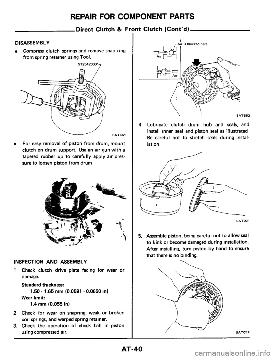
DISASSEMBLY
Compress clutch springs and remove snap ring
from spring retainer using
Tool.
e For easy removal of piston from drum, mount
clutch on drum support. Use an air gun with
a
tapered rubber up to carefully apply air pres-
sure to loosen piston from drum
INSPECTION AND ASSEMBLY
1 Check clutch drive plate facing for wear or
damage.
Standard thickness:
Wear limit:
2 Check for wear on snapring, weak or broken
coil springs, and warped spring retainer.
3. Check the operation of check ball in piston
using compressed air.
1.50 - 1.65 mrn (0.0591 - 0.0650 in)
1.4 mm (0.055 in)
LAW IS blocked here
SAT553
4 Lubricate clutch drum hub and seals, and
install inner
seal and piston seal as illustrated
Be careful not to stretch seals during instal-
lation
SAT031
5. Assemble piston, being careful not to allow seal
to kink or become damaged during installation.
After installing, turn piston
by hand to ensure
that there
is no binding.
/ .----icJ SAT032
AT-40
Page 45 of 99
REPAIR FOR COMPONENT PARTS
Brake Band and Band Servo
*Return rpnng
Band servo piston
Lathecvt ring real
\servo retainer
‘-Band servo piston stem
Lock nut SAT559
INSPECTION
inspect band frictlon rnaterlal for wear If
cracked, chipped or burnt spots are apparent,
replace the band.
SAT327
Check band %+NO components for wear and
scoring
AT-45