1984 CHEVROLET CAVALIER check engine
[x] Cancel search: check enginePage 53 of 105
Downloaded from www.Manualslib.com manuals search engine To store the sunshield when rennoved from the car, always select a place
where the sunshade can lay flat without anything stored on top of it or leaned against it. Hanging the sunshade flat on a wall by its hinges is an excellent way
to store it.
As with any decorative surface. washing with a mild soap and water solution is
recommended . Abrasive materials or chemical solvents may adversely affect
the finish of the sunshade.
FOLDING SEATBACK OPERATION
Station wagon and hatchback models are equipped with either a one-piece or split folding rear seatback which is not designed to lie flat, but does provide
additional load floor area when lowered .
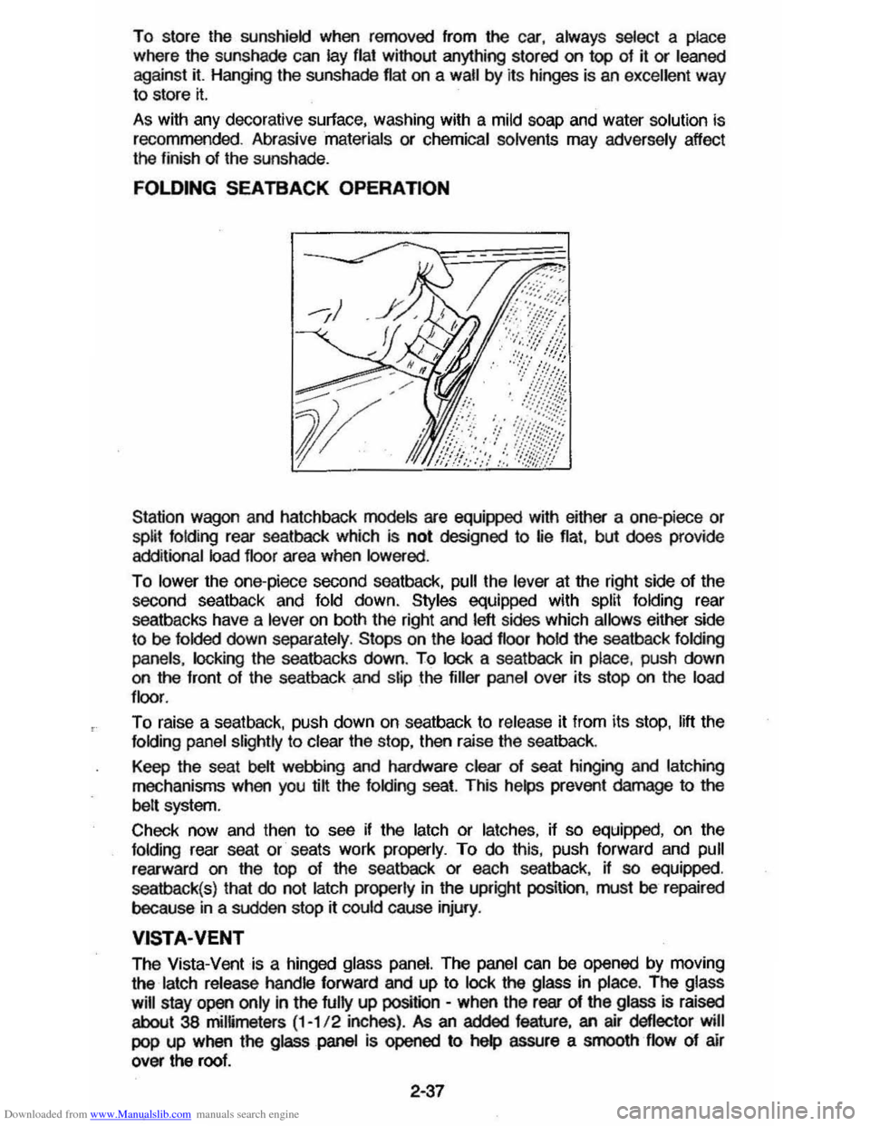
To lower the one-piece second seatback, pull the lever at the right side of the
second seatback and fold down. Styles equipped with split folding rear
seatbacks have a
lever on both the right and left sides which allows either side
to be folded down separately . Stops on the load floor hold the seatback folding
panels. locking
the seatbacks down. To lock a seatback in place, push down on the front of the seatback and slip the filler panel over its stop on the load
floor .
To raise a seat back. push down on seatback to release it from its stop. lift the folding panel slightly to clear the stop, then raise the seatback.
Keep the seat
belt webbing and hardware clear of seat hinging and latching
mechanisms when you @ the folding seat. This helps prevent damage to the
belt system.
Check now and then
to see if the latch or latches, if so equipped, on the folding rear seat or seats work properly. To do this, push forward and pull
rearward on the top of the seatback or each seatback, if so equipped.
seatback(s) that
do not latch properly in the upright position. must be repaired
because
in a sudden stop rt could cause injury.
VISTA·VENT
The Vista-Vent is a hinged glass panel. The panel can be opened by moving
the
latch release handle forward and up to lock the glass in place. The glass
will
stay open only in the fully up position -when the rear of the glass is raised
about 38 mimmeters (1-1/ 2 inches) . As an added feature, an air deflector will
pop up when the glass panel is opened to help assure a smooth flow of air
over the roof.
2·37
Page 54 of 105
Downloaded from www.Manualslib.com manuals search engine >1;' l ' "0'
VENT GLASS ~C"rl I / iT'--.... /.1 TO AEMOVE GLASS I,~ATCH ASSEMBlY
PUSH HERE TO ~ / SEPARATE THE @ ':ATCH ASSEM81. Y TRIM LACE~ i VISTA VENT GLASS STOWAGE BAG
/, ---~\~ ~STOWAGEBAG
\~ . ~~ ESCUTCHEON ASSEMBLY S', I I '
" I .,'
OPEN VISTA VENT INTERIOR VIEW VIEWA RETAINER
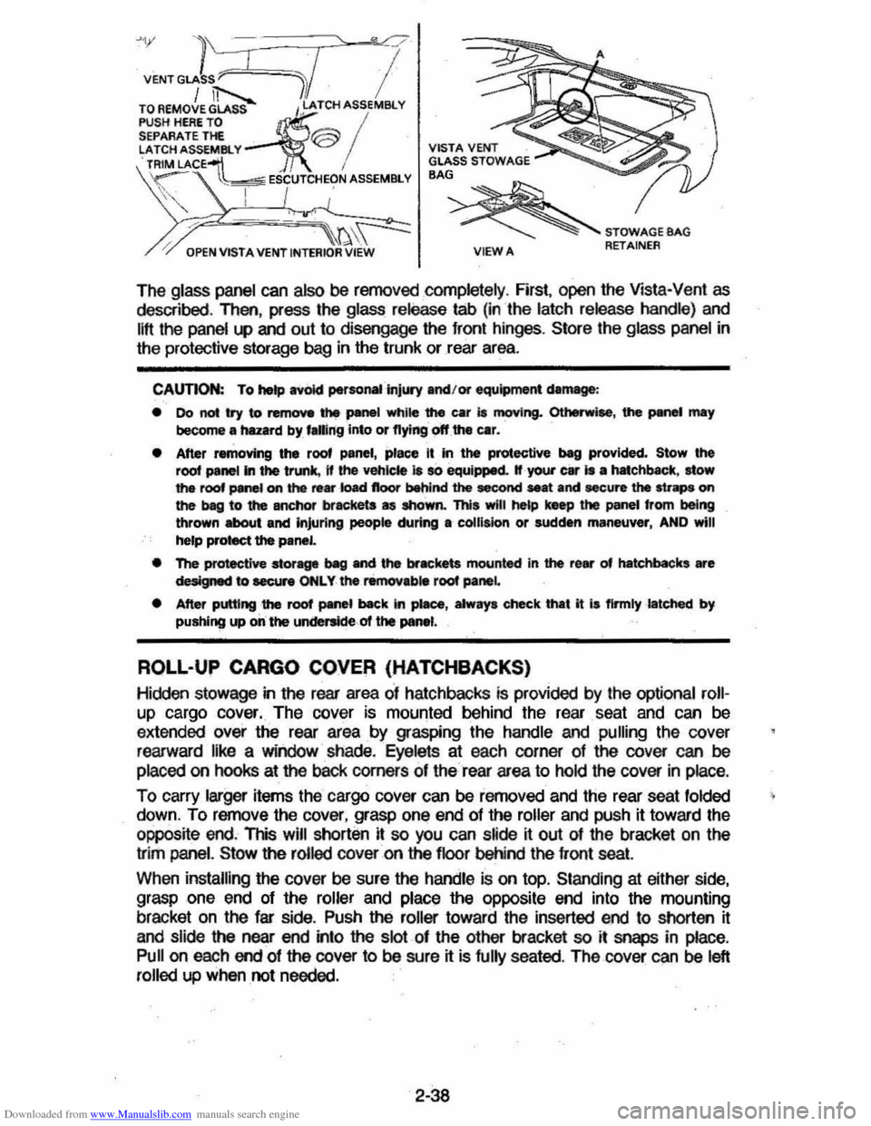
The glass panel can also be removed completely , First, open the Vista-Vent as described , Then, press the glass release tab (in the latch release handle) and
lift the panel
l.P and out to disengage the front hinges, Store the glass panel in
the protective storage bag in the trunk or rear area.
CAUTION: To hetp avoid perso ..... ·injUIY and/or equipment damage :
• 00 not try to remove the panel while the car is moving. Otherwise, the PMWI may become a hazard by, f.ling into or flying off the car.
• After removing the roof panel, place It in the protective beg provided. Stow the root panel In the trunk, 11 the vehicle 18 so equipped. If your car Is • hatchbKk, stow the roof panel on the re ... ·k)ad floor behind the second seat and secure the straps on the beg to the anchor brackets as shown. This will he&p keep the panel from being thrown about and Injuring people during a collision or sudden maneuver, AND will
help protect the panel.
• The protective stor-ve ~ and the brackets mounted in the rear of hatchbacks are designed to eecur. ONLY the removab. root panel
• After putting the roof panel back In piaee, alway. check that it I. flrmlylatehed by pushing up on the underside of the panel.
ROLL-UP CARGO COVER (HATCHBACKS)
Hidclen stowage in the rear area of hatchbacks is provided by the optional roll
up cargo cover. The cover is mounted behind the rear . seat and can be
extended over the rear area by grasping the handle and pulling the cover
rearward like a window shade.
Eyelets at each corner of the cover can be
placed on hooks at the baCk corners of the rear area to hold the cover in place.
To carry larger items the cargo cover can be removed and the rear seat folded
down, To remove the cover, grasp one end of the roller and push it toward the
opposite end. This
will shorten it so you can s~de ~ out of the bracket on the
trim
panel. Stow the rolled cover on the floor behind the front seat
When installing the cover be sure the handle is on top. Standing at either side,
grasp one end of the roller and place the
opPOSite end into the mounting
bracket on the far side . Push the roller toward the inserted end to shorten it
and slide the near
end into the slot of the other bracket so it snaps in place,
Pull on each end of the cover to be sure it is fully seated . The cover can be left
rolled up when not needed.
2-38
Page 57 of 105
Downloaded from www.Manualslib.com manuals search engine OJ ROOF RAIL ASM.
ill CROSSRAI LS
mCRO~RAIL KNOBS
[!)TIE-DOWNS
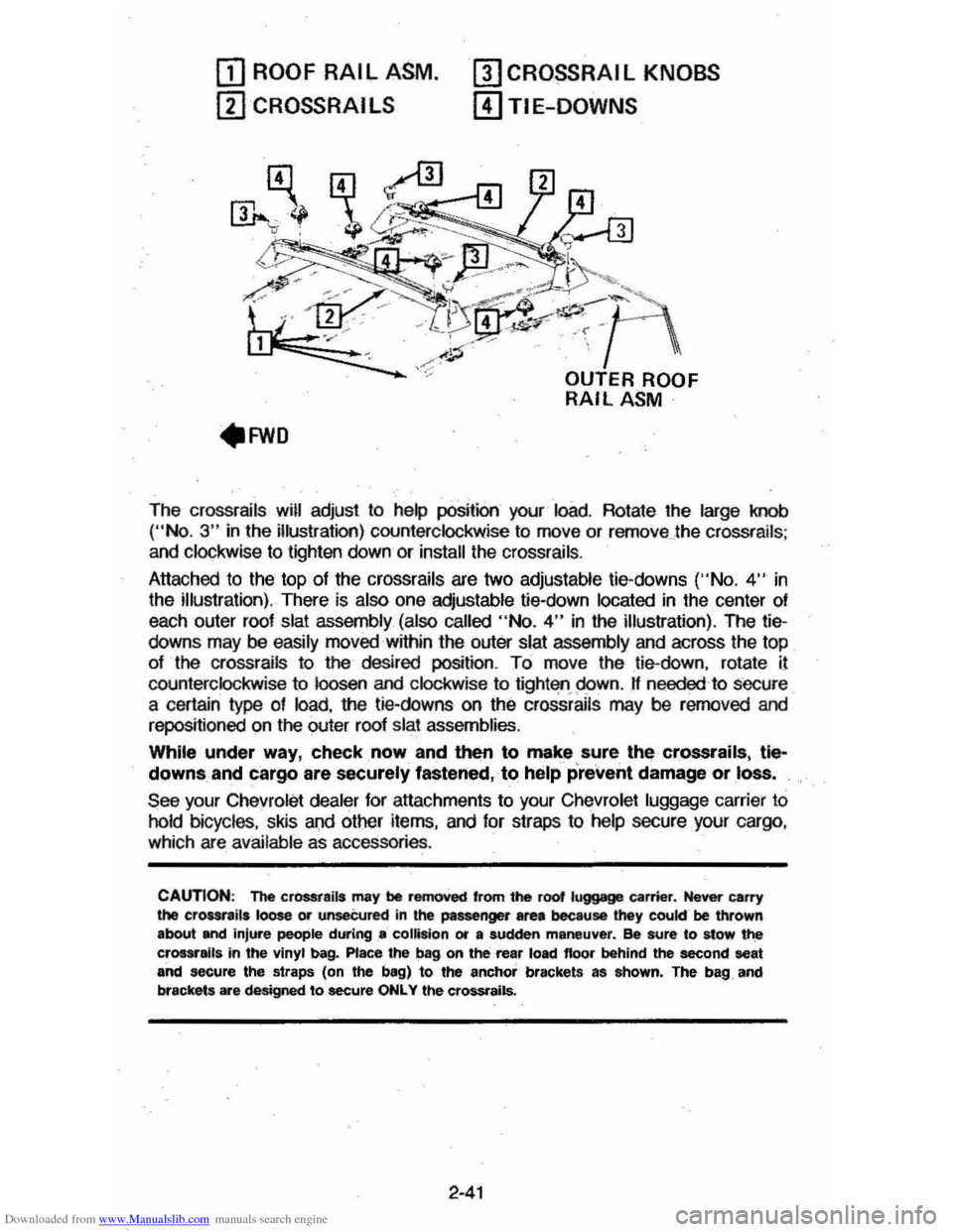
The crossrails will adjust to help position your load. Rotate the large knob ("No.3" in the illustration) counterclockwise to move or remove . the crossrails ;
and clockwise to lighten down or install the crossrails .
Attached to the top
of the crossrails are two adjustable tie-downs ('·No. 4" in
the illustration). There is also one adjustable tie-down located in the center of
each outer roof
slat assembly (also called "No.4" in the illustration). The tiedowns may be easily moved within the outer slat assembly and across the top
of the crossrails to the desired position. To move the tie-down, rotate il
counterclockwise to loosen and clockwise to tight'lfl.95>wn. If needed 'to secure
a certain type of load, the tie-downs on the crossrails may be rerncved and
repositioned on the outer roof slat assemblies.
While under way, check, now and then to make sure, the crossrails, tle~
downs, and cargo are securely fastened, to help prevent damage or loss.
See your Chevrolet dealer for attachments to your Chevrolet luggage carrier to
hold bicycles, skis and other items, and for straps to help secure your cargo ,
which are available as accessories .
CAUTION: The cr0SSt8ils may be removed 'rom the root luggage carrier. Never carry the crour,ils loose or unseCured in the passenger area because they cookr be thrown
about and injure people during .. collision or a sudden maneuver. ee sure to stow t~ crossralla in the vinyl bag. Place the bag on the rea, load floor behind the second seat and secure the straps (on the bag) to the anchor brackets as ahown. The bag, and
brackets are designed to secure ONLY the crossrails.
2-41
Page 64 of 105
Downloaded from www.Manualslib.com manuals search engine Stowage of Tire and Jack
CAUTION: Always securely reatow the, spare tire assembly (or flat tir.), all jacking
equipment, and the cover , using the means provided . When driving the car with the Compact Spare instel~. stow the ",Met COYer in the trunk. In station wagons and hatchbecks, when the rear seat Is folded down, stow the wheel cover nat on the rear floor behind the right front seat. When the r •• r' seat is up, stow the wheel cover in the rear area . This will help keep SUch1tung. trom being thrown about and injuring people during II colhion or • sudden maneuver ..
WHEEL NUT TORQUE
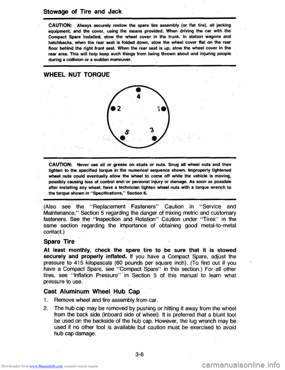
CAUTION:, Never use oil or grease on studs or nuts. Snug all wheel nuta and then tighten to the specified torque In the numerical sequence shown. Improperly tightened wheet nuts coukl eventually alk>w' the wheel to come off while the veh;ckt is 'moving, pOssibly , causing loss of control and/or pertonal injury or damage. As soon as possible after instilling any wheel, have II technician tighten wheel nuts with a torque wrench to the torque Mlown in "Specifications ," Section 6.
(Also see the "Replace ment F~st!3ners" Caution in "Servic e and
Maintenance," Section 5 regarding the danger of mixing metric and customary fasteners . See the "tnspection and Rotation" Caution under "Tires" in the
same section regarding the importance of obtaining
good metal-to-metal
contact.)
Spare Tire
At least monthly, check the spare tire to be sure that it is stowed
securely and properly inflated. If you have a Compact Spare, adjust the
pressure
to 415 kilopascals (60 pounds per square inch). (To find out if you have a COmpact Spare, see "Compact Spare " in this section .) For all other
tires, see "Inflation Pressure"-in Section 5 of this manual to learn what
pressure to use.
Cast Aluminum Wheel Hub Cap
1 . RerJ)ove wheel and tire assemb ly from car.
2 . The hub
cap may be removed by pushing or hitting it away from the wheel
from
the back side (inboard side of wheel) . It is pre ferred that a blunt tool be used on the backside of the hub cap. However, the lug wrench may be
used if no other tool is available but caution must be exercised to avoid hub cap damage .
3·6
Page 65 of 105

Downloaded from www.Manualslib.com manuals search engine 3. Install wheel and tire assembly and install hub cap by pushing or hitting
into place (the wheel can be mounted with hub cap in place). The hub cap
must be oriented by engaging the bump on the side of the hub cap
retention tab with the cutout on the side of the wheel pilot hole.
Compact Spare
The compact spare tire is designed to save space in your stowage area, and
its lighter weight makes it easier to install if a flat tire occurs. The lighter weight also helps improve fuel economy. ~--~------~~
" you have a flat tire, follow the jacking Instructions in this section, while keepingihese points in mind:
• Check the tire inflaiionpressureas soon as practical after installing the
spare (we suggest you use a 'pocket-type high'pressure inflation gage) and
adjust the pressure to 415
kilopascals (60 pounds per square inch). The
tire pressure should be checked at least monthly and kept at 415 kPa (60
psi) while the tire is stored . Also at least monthly , ·qheck that the spare lire is stowed securely ; tighten it if ~ is not.
NOTICE: Bee ... this tire is smaller than the standard tire, vehicle ground clearance is reduced. Do not take your vehicle through an automatic car wash while ~ spare I. Installed; the vehicle may catch on the equipment, possibly resulting In property damag_.
• YOU can expect a tread life up to 3,000 miles (4 800 kilometers), dependiQg on road conditions and your driving habits. The tire was designed to let you
finish an extended trip (up to 3,000 miles/4 800 kilometers) and buy a replacement tire, -if needed, at a store of your choice. However, to conserve
tire tread ~fe, return the spare to the stowage area as' soon as it is
convenient to have your standard tire repaired or replaced.
• Because the compact spare was specnically designed for your vehicle , ~ should not be used on any other vehicle.
• The compact spare tire and wheel are designed for use with each other.
The compact spare tire should not be mounted on any other type of wheel, and the compact spare wheel should not have any other type of tire
mounted on it. Also, do not try to use wheel covers or trim rings on the
CQr1l>aCt spare whe el since they will not fit. If such use is attempted,
damage to tIlese items or other vehicle components may occur.
• Do not use tire chains with your :compact spare tire. Because of the smaller tire size, a tire chain will not fit properly. This could cause damage to the
vehicle and result in loss of the chain.
3-7
Page 74 of 105
Downloaded from www.Manualslib.com manuals search engine SECTION 5
SERVICE AND MAINTENANCE
Your authorized dealer has factory trained technicians and Genuine GM Parts
to service your vehicle properly_ For expert advice and quality service, see your authorized dealer.
CAUTION: As with any machine, take care when making any check, doing any maintenance, or making any repair, to avoid being injured. Some of the MATERIALS in this vehicle may also be hazardous if used, serviced, or handled improperly. Improper or incomplete service can affect the vehicle itself which may in turn result in personal
injury, or damage to the vehicle or its equipment. H you have ANY question about carrying out some service, have the work done by a skilled technician.
REPLACEMENT FASTENERS
During vehicle maintenance, any fasteners used to replace older ones must
have the same measurements and strength as those removed, whether metric or customary. (The numbers on the heads of rnetric bons and on the surfaces
of metric nuts show their strength. Customary bolts use radial lines to show
this,
while most customary nuts do not have strength markings.) Fasteners
taken from the vehicle should be saved for re-use in the same spot when
possible. Where a fastener cannot be used again, take care to choose a
replacement that matches the old one. For information and help, see your
authorized dealer.
CAUTION: This vehicle is primarily dimensioned In the metric system. Most fasteners
are metric and many are very close in dimension to well· known customary fasteners in the inch system. Mismatched or incorrect fasteners can result in damage to the vehicle or possibly personal injury.
MAINTENANCE SCHEDULE
For owner convenience, a separate folder ,has. bee" providef;1 with your vehicle which outlines the maintenance your vehicle requires. The Maintenance
Schedule folder is supplemented by this section of the Owner's Manual.
Read this publication for a full understanding of your vehicle's maintenance
needs.
If you need a replacement Maintenance Schedule, see your dealer or contact the . Consumer . Aelations Representative, . Chevrolet Central Office,
Chevrolet Motor Division, Warren, MichigarL4809ll-13t~2-550Q1 (In Canada, contact the Customer Services Representative, General MotorsoT---
Canada LId., Oshawa, Ontario, L1J 5Z6; 416/644-6624).
FUEL CAP
The fuel cap is located behind a hinged door on the right'rear fender. For your
convenience there
is a fuel cap hanger located on the filler door.
The
fuel tank filler cap has a "s£rew-on ratcheting type" feature.
• To remove -rotate cap counterclockwise to clear the inside of the filler
neck. This will allow any residual pressure to escape.
• To install - reverse this procedure and tighten cap securely until a
"ratcheting",
clicking sound is heard indicating cap is on properly.
5-1
Page 75 of 105
Downloaded from www.Manualslib.com manuals search engine NOTICE: H you need to replace the fuel cap, use only a cap specified for your model. An incorrect fuel cap can result in a serious maHunction of the fuel system or emission control system. You can get a correct replacement cap from your dealer.
CATALYTIC CONVERTER
The catalytic converter is an emission control device added to the exhaust system to reduce exhaust gas pollutants. The converter contains
a ceramic material coated with noble metal catalysts. To prevent contamination
and loss of effectiveness of the catalysts. unleaded gasoline must be used.
Unleaded
gasoline also reduces spark plug fouling, exhaust system corrosion and engine oil deterioration. Leaded gasoline will also damage the oxygen
sensor
in the Computer Command Control system which could affect emission
control.
To help prevent damage:
1. Keep your engine properly maintained. Engine malfunctions involving the
electrical, carburetion, electronic fuel injection or ignition systems may
result in unusually high catalytic converter and exhaust system
temperatures which, under extreme malfunctioning conditions, may ignite
interior floor ·covering materials above the converter. Do not keep driving
your vehicle if you detect engine misfire, noticeable loss of
performance, or other unusual operating conditions. Instead, have it
serviced promptly. See the Maintenance Schedule folder for information on inspecting and maintaining the engine, exhaust system, and other
components.
2. Do not push or tow this vehicle to start it. This may result in unusually
high catalytic converter
and exhaust system temperatures which under
extreme conditions may ignite interior floor-covering material above the
converter.
Disregarding these instructions
could damage the catalytic converter, the vehicle, or nearby property and affect warranty coverage.
COMPUTER COMMAND CONTROL SYSTEM
Most vehicles sold in the United States (and some vehicles sold in Canada)
have the Computer Command Control system.
The Computer Command Control system monitors the exhaust stream with
an oxygen sensor. Based on sensor signals, the electronic control module adjusts
the air-fuel ratio
as needed. It is very important to use only unleaded
gasoline in vehicles equipped with the Computer Command Control system.
Leaded gasoline will damage the oxygen sensor,
and may affect emission
control.
"Check Engine" Light
Most vehicles sold in the United States (and some vehicles sold in Canada)
have the Computer Command Control system.
Vehicles
.with the Computer Command Control system, include a "CHECK
ENGINE" light
on the instrument panel designed to indicate the need for
system service. It will come on during engine starting to let you know the bulb
is working. (The
light will stay on a short time aiter the engine starts.) Have the
system repaired if the "CHECK ENGINE" light does not come on during engine
starting.
If the light comes on, either intermittently or continuously while driving,
service to the Computer Command Control system is required. Although in
5-2
Page 76 of 105
Downloaded from www.Manualslib.com manuals search engine most cases the vehicle is drivable, and does not require towing, see your
authorized dealer as soon as possible for service of the system.
Continued
driving without having the Computer Command Control system serviced could eventually cause damage to the emission control system. It
could
also affect fuel economy and drivability .
ENGINE OIL AND FILTER RECOMMENDATIONS
The following engine oil recommendations are based upon the operation . of your engine with the fuels recommended under "Fuel Requirements" in Section 2 of this manual.
Checking Oil Level
The engine oil must be kepi at the right level to help assure proper lubrication
of your vehicle's engine. n Is normal for an engine to use some oil, and some
engines may use more oil when they are new.
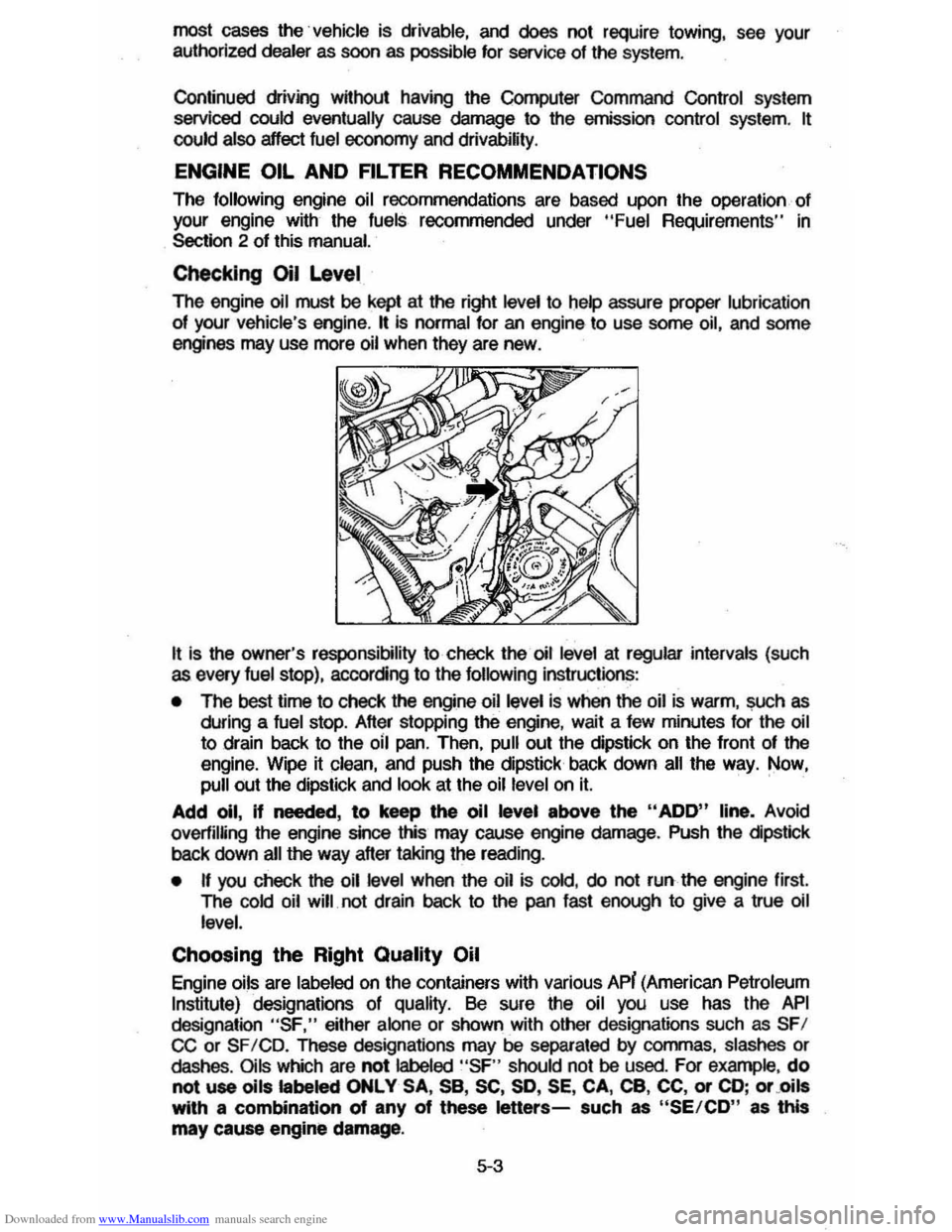
It is the owner's responsibility to check the oil level at regular intervals (such as every fuel stop), accorcing to the following instructions:
• The best time to check the engine oil level is when the oil is warm, ~h as
during a fuel stop. After stopping the engine, wait a few minutes for the oil
to drain back to the oil pan. Then, pull out the dipstick on the front of the
engine. Wipe it clean, and push the dipstick back down
all the way. Now, pull out the dipstick and look at the oil level on It. '
Add 011, If needed, to keep the 011 level above the "ADD" line, Avoid
overfilUng
the engine since this may cause engine damage. Push the cipstlck
back down all the way after taking the reading.
• n you check the oil level when the oil is cold, do not run the engine first.
The
cold oil will. not drain back to the pan fast enough to give a true oil
level.
Choosing the Right Quality Oil
Engine oils are labeled on the containers with various APi (American Petroleum
Institute) designations of quality. Be sure the oil you use has the API
designation "SF," either alone or shown with other designations such as SFI CC or SF ICD. These designations may be separated by commas. slashes or dashes. Oils which are not labeled "SF " should not be used. For example , do
not use oils labeled ONLY SA, sa, SC, SO, SE, CA, ca, CC, or CD; or .oils with a combination of any of these letters-such as "SE/CD" as this
may cause engine damage.
5·3