1983 FIAT UNO transmission oil
[x] Cancel search: transmission oilPage 214 of 303
Ignition unit
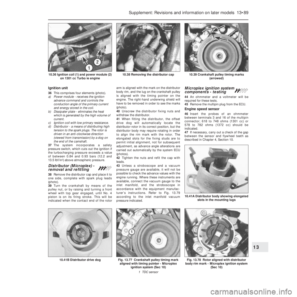
36This comprises four elements (photo).
a) Power module - receives the ignition
advance command and controls the
conduction angle of the primary current
and energy stored in the coil.
b) Dissipater plate - eliminates the heat
which is generated by the high volume of
current.
c) Ignition coil with low primary resistance.
d) Distributor - a means of distributing high
tension to the spark plugs. The rotor is
driven in an anti-clockwise direction
(viewed from transmission) by a dog on
the end of the camshaft.
37The system incorporates a safety
pressure switch, which cuts out the ignition if
the turbocharging pressure exceeds a value
of between 0.84 and 0.93 bars (12.2 and
13.5 lbf/in
2) above atmospheric pressure.
Distributor (Microplex) -
removal and refitting#
38Remove the distributor cap and place it to
one side, complete with spark plug leads
(photo).
39Turn the crankshaft by means of the
pulley nut, or by raising and turning a front
wheel with top gear engaged, until No. 4
piston is on its firing stroke. This will be
indicated when the contact end of the rotorarm is aligned with the mark on the distributor
body rim, and the lug on the crankshaft pulley
is aligned with the timing pointer on the
engine. The right-hand underwing shield will
have to be removed in order to see the marks
(photo).
40Unscrew the distributor fixing nuts and
withdraw the distributor.
41When fitting the distributor, the offset
drive dog will automatically locate the
distributor rotor in its correct position, but the
distributor body may require rotating in order
to align the rim mark with the rotor. The
elongated slots for the fixing studs are to
permit initial alignment, not for subsequent
adjustment, as advance angle alterations are
carried out automatically by the system ECU
(photos).
42Tighten the nuts and refit the cap with
leads.
43Unless a stroboscope and a vacuum
pressure gauge are available, it will not be
possible to check the advance values with the
engine running. Where these instruments are
available, connect the vacuum gauge to the
inlet manifold, and the stroboscope in
accordance with the equipment manufac-
turer’s instructions. Refer to Fig. 13.79
according to the inlet manifold vacuum
pressure indicated.
Microplex ignition system
components - testing ª
44An ohmmeter and a voltmeter will be
required for these tests.
45Remove the multipin plug from the ECU.
Engine speed sensor
46Insert the probes of an ohmmeter
between terminals 3 and 16 of the multipin
connector; 618 to 748 ohms (1301 cc) or
578 to 782 ohms (1372 cc) should be
indicated.
47If necessary, carry out a check of the gap
between the sensor and flywheel teeth as
described in Chapter 4, Section 10.
Supplement: Revisions and information on later models 13•89
10.39 Crankshaft pulley timing marks
(arrowed)10.38 Removing the distributor cap10.36 Ignition coil (1) and power module (2)
on 1301 cc Turbo ie engine
Fig. 13.78 Rotor aligned with distributor
body rim mark - Microplex ignition system
(Sec 10)
10.41A Distributor body showing elongated
slots in the mounting lugs
Fig. 13.77 Crankshaft pulley timing mark
aligned with timing pointer - Microplex
ignition system (Sec 10)
1 TDC sensor10.41B Distributor drive dog
13
Page 219 of 303
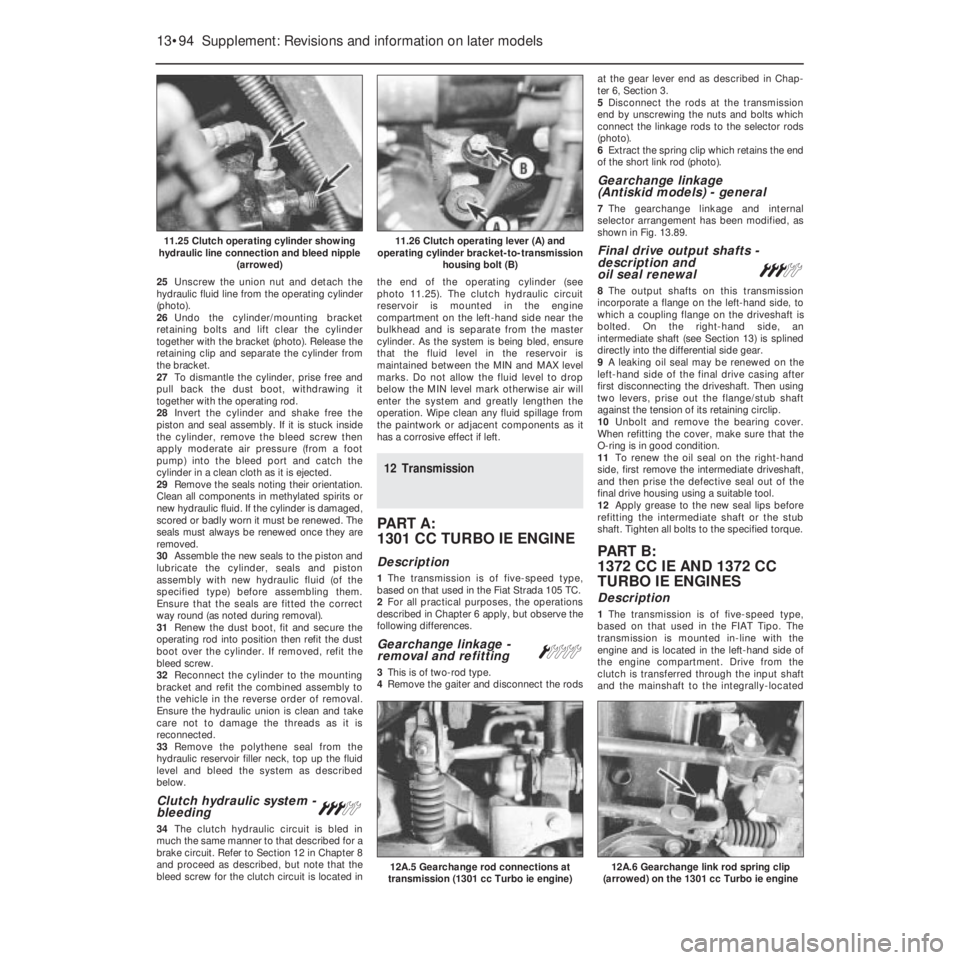
25Unscrew the union nut and detach the
hydraulic fluid line from the operating cylinder
(photo).
26Undo the cylinder/mounting bracket
retaining bolts and lift clear the cylinder
together with the bracket (photo). Release the
retaining clip and separate the cylinder from
the bracket.
27To dismantle the cylinder, prise free and
pull back the dust boot, withdrawing it
together with the operating rod.
28Invert the cylinder and shake free the
piston and seal assembly. If it is stuck inside
the cylinder, remove the bleed screw then
apply moderate air pressure (from a foot
pump) into the bleed port and catch the
cylinder in a clean cloth as it is ejected.
29Remove the seals noting their orientation.
Clean all components in methylated spirits or
new hydraulic fluid. If the cylinder is damaged,
scored or badly worn it must be renewed. The
seals must always be renewed once they are
removed.
30Assemble the new seals to the piston and
lubricate the cylinder, seals and piston
assembly with new hydraulic fluid (of the
specified type) before assembling them.
Ensure that the seals are fitted the correct
way round (as noted during removal).
31Renew the dust boot, fit and secure the
operating rod into position then refit the dust
boot over the cylinder. If removed, refit the
bleed screw.
32Reconnect the cylinder to the mounting
bracket and refit the combined assembly to
the vehicle in the reverse order of removal.
Ensure the hydraulic union is clean and take
care not to damage the threads as it is
reconnected.
33Remove the polythene seal from the
hydraulic reservoir filler neck, top up the fluid
level and bleed the system as described
below.
Clutch hydraulic system -
bleeding#
34The clutch hydraulic circuit is bled in
much the same manner to that described for a
brake circuit. Refer to Section 12 in Chapter 8
and proceed as described, but note that the
bleed screw for the clutch circuit is located inthe end of the operating cylinder (see
photo 11.25). The clutch hydraulic circuit
reservoir is mounted in the engine
compartment on the left-hand side near the
bulkhead and is separate from the master
cylinder. As the system is being bled, ensure
that the fluid level in the reservoir is
maintained between the MIN and MAX level
marks. Do not allow the fluid level to drop
below the MIN level mark otherwise air will
enter the system and greatly lengthen the
operation. Wipe clean any fluid spillage from
the paintwork or adjacent components as it
has a corrosive effect if left.
12 Transmission
PART A:
1301 CC TURBO IE ENGINE
Description
1The transmission is of five-speed type,
based on that used in the Fiat Strada 105 TC.
2For all practical purposes, the operations
described in Chapter 6 apply, but observe the
following differences.
Gearchange linkage -
removal and refitting Á
3This is of two-rod type.
4Remove the gaiter and disconnect the rodsat the gear lever end as described in Chap-
ter 6, Section 3.
5Disconnect the rods at the transmission
end by unscrewing the nuts and bolts which
connect the linkage rods to the selector rods
(photo).
6Extract the spring clip which retains the end
of the short link rod (photo).
Gearchange linkage
(Antiskid models) - general
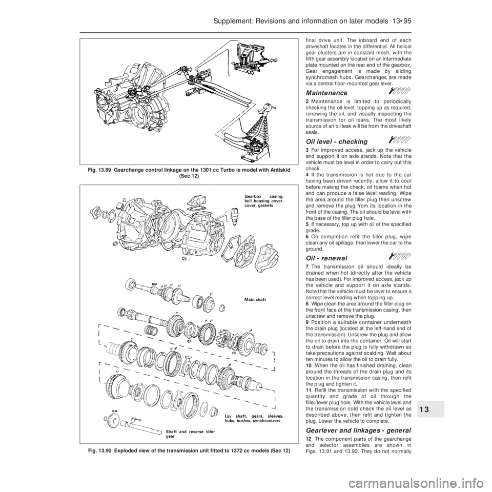
7The gearchange linkage and internal
selector arrangement has been modified, as
shown in Fig. 13.89.
Final drive output shafts -
description and
oil seal renewal
#
8The output shafts on this transmission
incorporate a flange on the left-hand side, to
which a coupling flange on the driveshaft is
bolted. On the right-hand side, an
intermediate shaft (see Section 13) is splined
directly into the differential side gear.
9A leaking oil seal may be renewed on the
left-hand side of the final drive casing after
first disconnecting the driveshaft. Then using
two levers, prise out the flange/stub shaft
against the tension of its retaining circlip.
10Unbolt and remove the bearing cover.
When refitting the cover, make sure that the
O-ring is in good condition.
11To renew the oil seal on the right-hand
side, first remove the intermediate driveshaft,
and then prise the defective seal out of the
final drive housing using a suitable tool.
12Apply grease to the new seal lips before
refitting the intermediate shaft or the stub
shaft. Tighten all bolts to the specified torque.
PART B:
1372 CC IE AND 1372 CC
TURBO IE ENGINES
Description
1The transmission is of five-speed type,
based on that used in the FIAT Tipo. The
transmission is mounted in-line with the
engine and is located in the left-hand side of
the engine compartment. Drive from the
clutch is transferred through the input shaft
and the mainshaft to the integrally-located
13•94 Supplement: Revisions and information on later models
12A.6 Gearchange link rod spring clip
(arrowed) on the 1301 cc Turbo ie engine12A.5 Gearchange rod connections at
transmission (1301 cc Turbo ie engine)
11.26 Clutch operating lever (A) and
operating cylinder bracket-to-transmission
housing bolt (B)11.25 Clutch operating cylinder showing
hydraulic line connection and bleed nipple
(arrowed)
Page 220 of 303
final drive unit. The inboard end of each
driveshaft locates in the differential. All helical
gear clusters are in constant mesh, with the
fifth gear assembly located on an intermediate
plate mounted on the rear end of the gearbox.
Gear engagement is made by sliding
synchromesh hubs. Gearchanges are made
via a central floor-mounted gear lever.
MaintenanceÁ
2Maintenance is limited to periodically
checking the oil level, topping up as required,
renewing the oil, and visually inspecting the
transmission for oil leaks. The most likely
source of an oil leak will be from the driveshaft
seals.
Oil level - checkingÁ
3For improved access, jack up the vehicle
and support it on axle stands. Note that the
vehicle must be level in order to carry out this
check.
4If the transmission is hot due to the car
having been driven recently, allow it to cool
before making the check; oil foams when hot
and can produce a false level reading. Wipe
the area around the filler plug then unscrew
and remove the plug from its location in the
front of the casing. The oil should be level with
the base of the filler plug hole.
5If necessary, top up with oil of the specified
grade.
6On completion refit the filler plug, wipe
clean any oil spillage, then lower the car to the
ground.
Oil - renewalÁ
7The transmission oil should ideally be
drained when hot (directly after the vehicle
has been used). For improved access, jack up
the vehicle and support it on axle stands.
Note that the vehicle must be level to ensure a
correct level reading when topping up.
8Wipe clean the area around the filler plug on
the front face of the transmission casing, then
unscrew and remove the plug.
9Position a suitable container underneath
the drain plug (located at the left-hand end of
the transmission). Unscrew the plug and allow
the oil to drain into the container. Oil will start
to drain before the plug is fully withdrawn so
take precautions against scalding. Wait about
ten minutes to allow the oil to drain fully.
10When the oil has finished draining, clean
around the threads of the drain plug and its
location in the transmission casing, then refit
the plug and tighten it.
11Refill the transmission with the specified
quantity and grade of oil through the
filler/lever plug hole. With the vehicle level and
the transmission cold check the oil level as
described above, then refit and tighten the
plug. Lower the vehicle to complete.
Gearlever and linkages - general
12The component parts of the gearchange
and selector assemblies are shown in
Figs. 13.91 and 13.92. They do not normally
Supplement: Revisions and information on later models 13•95
Fig. 13.90 Exploded view of the transmission unit fitted to 1372 cc models (Sec 12)
13
Fig. 13.89 Gearchange control linkage on the 1301 cc Turbo ie model with Antiskid
(Sec 12)
Page 221 of 303
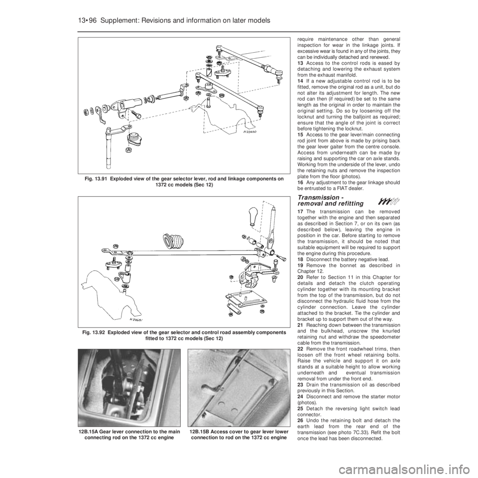
require maintenance other than general
inspection for wear in the linkage joints. If
excessive wear is found in any of the joints, they
can be individually detached and renewed.
13Access to the control rods is eased by
detaching and lowering the exhaust system
from the exhaust manifold.
14If a new adjustable control rod is to be
fitted, remove the original rod as a unit, but do
not alter its adjustment for length. The new
rod can then (if required) be set to the same
length as the original in order to maintain the
original setting. Do so by loosening off the
locknut and turning the balljoint as required;
ensure that the angle of the joint is correct
before tightening the locknut.
15Access to the gear lever/main connecting
rod joint from above is made by prising back
the gear lever gaiter from the centre console.
Access from underneath can be made by
raising and supporting the car on axle stands.
Working from the underside of the lever, undo
the retaining nuts and remove the inspection
plate from the floor (photos).
16Any adjustment to the gear linkage should
be entrusted to a FIAT dealer.
Transmission -
removal and refitting#
17The transmission can be removed
together with the engine and then separated
as described in Section 7, or on its own (as
described below), leaving the engine in
position in the car. Before starting to remove
the transmission, it should be noted that
suitable equipment will be required to support
the engine during this procedure.
18Disconnect the battery negative lead.
19Remove the bonnet as described in
Chapter 12.
20Refer to Section 11 in this Chapter for
details and detach the clutch operating
cylinder together with its mounting bracket
from the top of the transmission, but do not
disconnect the hydraulic fluid hose from the
cylinder connection. Leave the cylinder
attached to the bracket. Tie the cylinder and
bracket up to support them out of the way.
21Reaching down between the transmission
and the bulkhead, unscrew the knurled
retaining nut and withdraw the speedometer
cable from the transmission.
22Remove the front roadwheel trims, then
loosen off the front wheel retaining bolts.
Raise the vehicle and support it on axle
stands at a suitable height to allow working
underneath and eventual transmission
removal from under the front end.
23Drain the transmission oil as described
previously in this Section.
24Disconnect and remove the starter motor
(photos).
25Detach the reversing light switch lead
connector.
26Undo the retaining bolt and detach the
earth lead from the rear end of the
transmission (see photo 7C.33). Refit the bolt
once the lead has been disconnected.
13•96 Supplement: Revisions and information on later models
12B.15B Access cover to gear lever lower
connection to rod on the 1372 cc engine
Fig. 13.92 Exploded view of the gear selector and control road assembly components
fitted to 1372 cc models (Sec 12)
12B.15A Gear lever connection to the main
connecting rod on the 1372 cc engine
Fig. 13.91 Exploded view of the gear selector lever, rod and linkage components on
1372 cc models (Sec 12)
Page 222 of 303
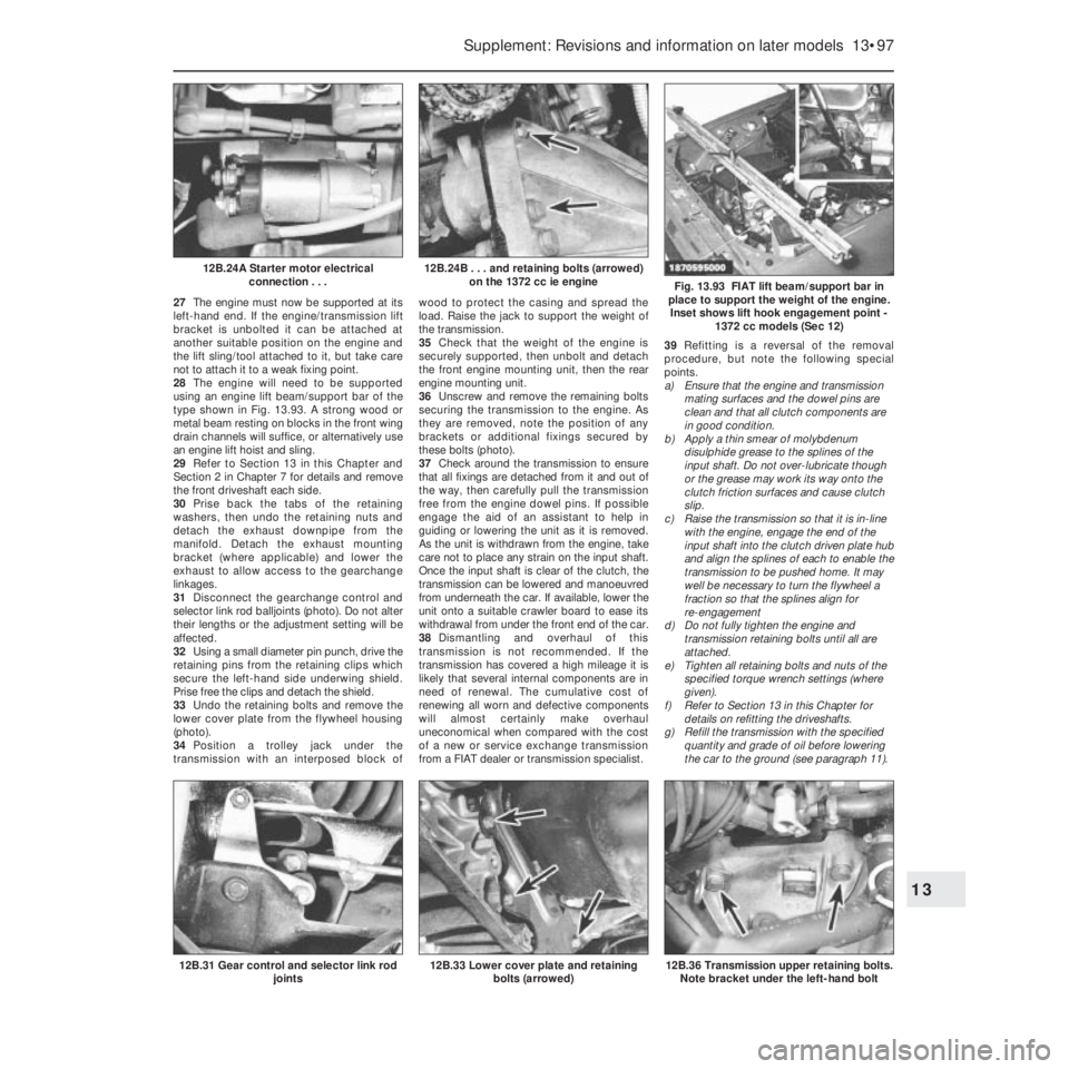
27The engine must now be supported at its
left-hand end. If the engine/transmission lift
bracket is unbolted it can be attached at
another suitable position on the engine and
the lift sling/tool attached to it, but take care
not to attach it to a weak fixing point.
28The engine will need to be supported
using an engine lift beam/support bar of the
type shown in Fig. 13.93. A strong wood or
metal beam resting on blocks in the front wing
drain channels will suffice, or alternatively use
an engine lift hoist and sling.
29Refer to Section 13 in this Chapter and
Section 2 in Chapter 7 for details and remove
the front driveshaft each side.
30Prise back the tabs of the retaining
washers, then undo the retaining nuts and
detach the exhaust downpipe from the
manifold. Detach the exhaust mounting
bracket (where applicable) and lower the
exhaust to allow access to the gearchange
linkages.
31Disconnect the gearchange control and
selector link rod balljoints (photo). Do not alter
their lengths or the adjustment setting will be
affected.
32Using a small diameter pin punch, drive the
retaining pins from the retaining clips which
secure the left-hand side underwing shield.
Prise free the clips and detach the shield.
33Undo the retaining bolts and remove the
lower cover plate from the flywheel housing
(photo).
34Position a trolley jack under the
transmission with an interposed block ofwood to protect the casing and spread the
load. Raise the jack to support the weight of
the transmission.
35Check that the weight of the engine is
securely supported, then unbolt and detach
the front engine mounting unit, then the rear
engine mounting unit.
36Unscrew and remove the remaining bolts
securing the transmission to the engine. As
they are removed, note the position of any
brackets or additional fixings secured by
these bolts (photo).
37Check around the transmission to ensure
that all fixings are detached from it and out of
the way, then carefully pull the transmission
free from the engine dowel pins. If possible
engage the aid of an assistant to help in
guiding or lowering the unit as it is removed.
As the unit is withdrawn from the engine, take
care not to place any strain on the input shaft.
Once the input shaft is clear of the clutch, the
transmission can be lowered and manoeuvred
from underneath the car. If available, lower the
unit onto a suitable crawler board to ease its
withdrawal from under the front end of the car.
38Dismantling and overhaul of this
transmission is not recommended. If the
transmission has covered a high mileage it is
likely that several internal components are in
need of renewal. The cumulative cost of
renewing all worn and defective components
will almost certainly make overhaul
uneconomical when compared with the cost
of a new or service exchange transmission
from a FIAT dealer or transmission specialist.39Refitting is a reversal of the removal
procedure, but note the following special
points.
a) Ensure that the engine and transmission
mating surfaces and the dowel pins are
clean and that all clutch components are
in good condition.
b) Apply a thin smear of molybdenum
disulphide grease to the splines of the
input shaft. Do not over-lubricate though
or the grease may work its way onto the
clutch friction surfaces and cause clutch
slip.
c) Raise the transmission so that it is in-line
with the engine, engage the end of the
input shaft into the clutch driven plate hub
and align the splines of each to enable the
transmission to be pushed home. It may
well be necessary to turn the flywheel a
fraction so that the splines align for
re-engagement
d) Do not fully tighten the engine and
transmission retaining bolts until all are
attached.
e) Tighten all retaining bolts and nuts of the
specified torque wrench settings (where
given).
f) Refer to Section 13 in this Chapter for
details on refitting the driveshafts.
g) Refill the transmission with the specified
quantity and grade of oil before lowering
the car to the ground (see paragraph 11).
Supplement: Revisions and information on later models 13•97
Fig. 13.93 FIAT lift beam/support bar in
place to support the weight of the engine.
Inset shows lift hook engagement point -
1372 cc models (Sec 12)
12B.24B . . . and retaining bolts (arrowed)
on the 1372 cc ie engine12B.24A Starter motor electrical
connection . . .
12B.36 Transmission upper retaining bolts.
Note bracket under the left-hand bolt12B.33 Lower cover plate and retaining
bolts (arrowed)12B.31 Gear control and selector link rod
joints
13
Page 224 of 303
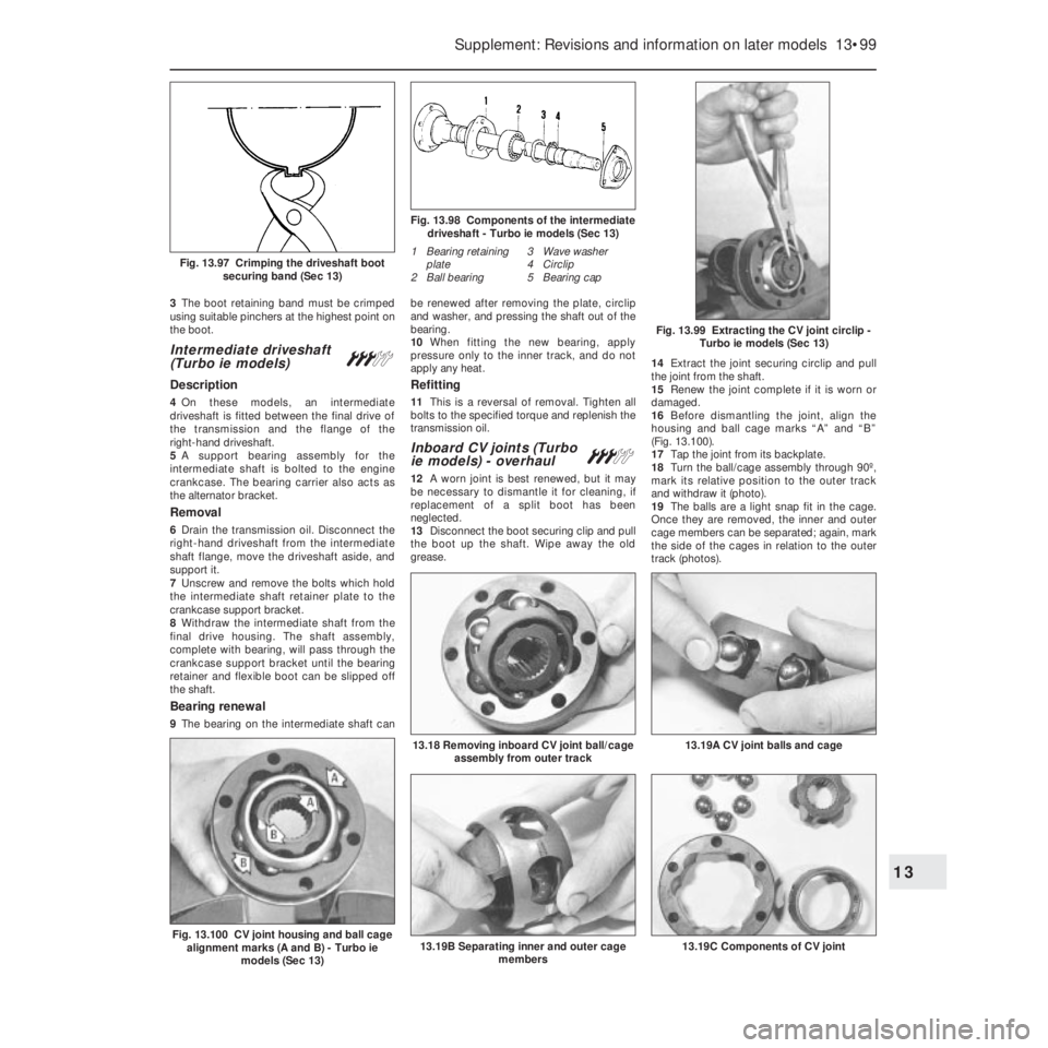
3The boot retaining band must be crimped
using suitable pinchers at the highest point on
the boot.
Intermediate driveshaft
(Turbo ie models) #
Description
4On these models, an intermediate
driveshaft is fitted between the final drive of
the transmission and the flange of the
right-hand driveshaft.
5A support bearing assembly for the
intermediate shaft is bolted to the engine
crankcase. The bearing carrier also acts as
the alternator bracket.
Removal
6Drain the transmission oil. Disconnect the
right-hand driveshaft from the intermediate
shaft flange, move the driveshaft aside, and
support it.
7Unscrew and remove the bolts which hold
the intermediate shaft retainer plate to the
crankcase support bracket.
8Withdraw the intermediate shaft from the
final drive housing. The shaft assembly,
complete with bearing, will pass through the
crankcase support bracket until the bearing
retainer and flexible boot can be slipped off
the shaft.
Bearing renewal
9The bearing on the intermediate shaft canbe renewed after removing the plate, circlip
and washer, and pressing the shaft out of the
bearing.
10When fitting the new bearing, apply
pressure only to the inner track, and do not
apply any heat.
Refitting
11This is a reversal of removal. Tighten all
bolts to the specified torque and replenish the
transmission oil.
Inboard CV joints (Turbo
ie models) - overhaul #
12A worn joint is best renewed, but it may
be necessary to dismantle it for cleaning, if
replacement of a split boot has been
neglected.
13Disconnect the boot securing clip and pull
the boot up the shaft. Wipe away the old
grease. 14Extract the joint securing circlip and pull
the joint from the shaft.
15Renew the joint complete if it is worn or
damaged.
16Before dismantling the joint, align the
housing and ball cage marks “A” and “B”
(Fig. 13.100).
17Tap the joint from its backplate.
18Turn the ball/cage assembly through 90º,
mark its relative position to the outer track
and withdraw it (photo).
19The balls are a light snap fit in the cage.
Once they are removed, the inner and outer
cage members can be separated; again, mark
the side of the cages in relation to the outer
track (photos).
Supplement: Revisions and information on later models 13•99
Fig. 13.99 Extracting the CV joint circlip -
Turbo ie models (Sec 13)
Fig. 13.98 Components of the intermediate
driveshaft - Turbo ie models (Sec 13)
1 Bearing retaining
plate
2 Ball bearing3 Wave washer
4 Circlip
5 Bearing cap
Fig. 13.97 Crimping the driveshaft boot
securing band (Sec 13)
13.19C Components of CV joint13.19B Separating inner and outer cage
members
13.19A CV joint balls and cage13.18 Removing inboard CV joint ball/cage
assembly from outer track
Fig. 13.100 CV joint housing and ball cage
alignment marks (A and B) - Turbo ie
models (Sec 13)
13
Page 236 of 303

Door closure sensor
117The sensor consists of a microswitch
within the lock. The switch actuates the
warning lamp according to whether the lock is
in the open or closed mode.
Check control system sensors -
testing
Brake fluid level sensor
118With the fluid level correct, switch on the
ignition and depress the centre of the
reservoir cap. If the sensor switches are
working correctly, then “FAULT” should be
indicated on the check panel.
Coolant level sensor
119With the coolant level in the expansion
tank correct, switch on the ignition and then
pull the wiring plug from the sensor. “FAULT”
should be indicated on the check panel. If it is
not, then it is the panel which is faulty.
120An ohmmeter should be used to check
for continuity, holding the float in both the full
and low level positions.
Engine oil level sensor
121With the oil level correct, disconnect the
wiring plug from the dipstick, and then bridge
the plug terminals (not dipstick side) with a 12
ohm resistor. Switch on the ignition.
122If the red light on the check panel goes
out, then the fault is due to the sensor.
123If the light stays on, then it is the check
panel module which is faulty.
Door closure sensor
124Any fault in the lock microswitch can best
be detected using an ohmmeter.
16 Suspension
Front anti-roll bar -
removal and refittingª
1A front anti-roll bar is fitted to the 1301 cc,
1372 cc ie and 1372 cc Turbo ie engined
models. Removal of the bar on all models isas follows. Firstly loosen off the front
roadwheel bolts, then raise the front of the
car, securely support it on axle stands and
remove the front roadwheels.
2Disconnect the two gearchange rods from
the transmission.
3Unbolt and disconnect the anti-roll bar
insulating clamps from the floorpan (photo).
4Unbolt the end links from the track control
arms and withdraw the anti-roll bar (photo).
5Refitting is a reversal of removal, but only
tighten the nuts and bolts to the specified
torque with the car parked on level ground,
with four passengers and 40 kg of luggage
inside.
Suspension strut - later models
6The suspension strut upper mounting nuts
on later models also secure the brackets for
the mounting of ancillary components such as
the fuel filter, fuel system relays and fuses,
etc. (depending on model).
7When removing the suspension strut units,
it will therefore be necessary to detach and
support these brackets and their fittings
(photo).
17 Bodywork
Plastic components
1With the use of more and more plastic
body components by the vehicle
manufacturers (e.g. bumpers, spoilers, and in
some cases major body panels), rectification
of more serious damage to such items has
become a matter of either entrusting repair
work to a specialist in this field, or renewing
complete components. Repair of such
damage by the DIY owner is not really
feasible owing to the cost of the equipment
and materials required for effecting such
repairs. The basic technique involves making
a groove along the line of the crack in the
plastic using a rotary burr in a power drill. The
damaged part is then welded back togetherby using a hot air gun to heat up and fuse a
plastic filler rod into the groove. Any excess
plastic is then removed and the area rubbed
down to a smooth finish. It is important that a
filler rod of the correct plastic is used, as
body components can be made of a variety
of different types (e.g. polycarbonate, ABS,
polypropylene). Damage of a less serious
nature (abrasions, minor cracks, etc.) can be
repaired by the DIY owner using a two-part
epoxy filler repair material. Once mixed in
equal proportions, this is used in similar
fashion to the bodywork filler used on metal
panels. The filler is usually cured in twenty to
thirty minutes, ready for sanding and
painting.
2If the owner is renewing a complete
component himself, or if he has repaired it
with epoxy filler, he will be left with the
problem of finding a suitable paint for
finishing which is compatible with the type of
plastic used. At one time the use of a
universal paint was not possible owing to the
complex range of plastics encountered in
body component applications. Standard
paints, generally speaking, will not bond to
plastic or rubber satisfactorily. However, it is
now possible to obtain a plastic body parts
finishing kit which consists of a pre-primer
treatment, a primer and coloured top coat.
Full instructions are normally supplied with a
kit, but basically the method of use is to first
apply the pre-primer to the component
concerned and allow it to dry for up to
30 minutes. Then the primer is applied and
left to dry for about an hour before finally
applying the special coloured top coat. The
result is a correctly coloured component
where the paint will flex with the plastic or
rubber, a property that standard paint does
not normally possess.
Rear view mirrors Á
Interior
3The mirror is of safety type, “breaking” off
its ball fixing upon impact from a front seat
occupant.
4To remove the mirror, grip the head and
Supplement: Revisions and information on later models 13•111
16.7 Suspension strut upper mounting
nuts, showing bracket and cable clip on
the 1372 cc ie model16.4 Anti-roll bar fixing nuts (arrowed)16.3 Anti-roll bar clamp
13
Page 298 of 303

Glossary of Technical TermsREF•15
REF
GGapThe distance the spark must travel in
jumping from the centre electrode to the side
electrode in a spark plug. Also refers to the
spacing between the points in a contact
breaker assembly in a conventional points-
type ignition, or to the distance between the
reluctor or rotor and the pickup coil in an
electronic ignition.
GasketAny thin, soft material - usually cork,
cardboard, asbestos or soft metal - installed
between two metal surfaces to ensure a good
seal. For instance, the cylinder head gasket
seals the joint between the block and the
cylinder head.
GaugeAn instrument panel display used to
monitor engine conditions. A gauge with a
movable pointer on a dial or a fixed scale is an
analogue gauge. A gauge with a numerical
readout is called a digital gauge.
HHalfshaftA rotating shaft that transmits
power from the final drive unit to a drive
wheel, usually when referring to a live rear
axle.
Harmonic balancerA device designed to
reduce torsion or twisting vibration in the
crankshaft. May be incorporated in the
crankshaft pulley. Also known as a vibration
damper.
HoneAn abrasive tool for correcting small
irregularities or differences in diameter in an
engine cylinder, brake cylinder, etc.
Hydraulic tappetA tappet that utilises
hydraulic pressure from the engine’s
lubrication system to maintain zero clearance
(constant contact with both camshaft and
valve stem). Automatically adjusts to variation
in valve stem length. Hydraulic tappets also
reduce valve noise.
IIgnition timingThe moment at which the
spark plug fires, usually expressed in the
number of crankshaft degrees before the
piston reaches the top of its stroke.
Inlet manifoldA tube or housing with
passages through which flows the air-fuel
mixture (carburettor vehicles and vehicles with
throttle body injection) or air only (port fuel-
injected vehicles) to the port openings in the
cylinder head.
JJump startStarting the engine of a vehicle
with a discharged or weak battery by
attaching jump leads from the weak battery to
a charged or helper battery.
LLoad Sensing Proportioning Valve (LSPV)A
brake hydraulic system control valve that
works like a proportioning valve, but also
takes into consideration the amount of weight
carried by the rear axle.
LocknutA nut used to lock an adjustment
nut, or other threaded component, in place.
For example, a locknut is employed to keep
the adjusting nut on the rocker arm in
position.
LockwasherA form of washer designed to
prevent an attaching nut from working loose.
MMacPherson strutA type of front
suspension system devised by Earle
MacPherson at Ford of England. In its original
form, a simple lateral link with the anti-roll bar
creates the lower control arm. A long strut - an
integral coil spring and shock absorber - is
mounted between the body and the steering
knuckle. Many modern so-called MacPherson
strut systems use a conventional lower A-arm
and don’t rely on the anti-roll bar for location.
MultimeterAn electrical test instrument with
the capability to measure voltage, current and
resistance.
NNOxOxides of Nitrogen. A common toxic
pollutant emitted by petrol and diesel engines
at higher temperatures.
OOhmThe unit of electrical resistance. One
volt applied to a resistance of one ohm will
produce a current of one amp.
OhmmeterAn instrument for measuring
electrical resistance.
O-ringA type of sealing ring made of a
special rubber-like material; in use, the O-ring
is compressed into a groove to provide the
sealing action.
Overhead cam (ohc) engineAn engine with
the camshaft(s) located on top of the cylinder
head(s).Overhead valve (ohv) engineAn engine with
the valves located in the cylinder head, but
with the camshaft located in the engine block.
Oxygen sensorA device installed in the
engine exhaust manifold, which senses the
oxygen content in the exhaust and converts
this information into an electric current. Also
called a Lambda sensor.
PPhillips screwA type of screw head having a
cross instead of a slot for a corresponding
type of screwdriver.
PlastigageA thin strip of plastic thread,
available in different sizes, used for measuring
clearances. For example, a strip of Plastigage
is laid across a bearing journal. The parts are
assembled and dismantled; the width of the
crushed strip indicates the clearance between
journal and bearing.
Propeller shaftThe long hollow tube with
universal joints at both ends that carries
power from the transmission to the differential
on front-engined rear wheel drive vehicles.
Proportioning valveA hydraulic control
valve which limits the amount of pressure to
the rear brakes during panic stops to prevent
wheel lock-up.
RRack-and-pinion steeringA steering system
with a pinion gear on the end of the steering
shaft that mates with a rack (think of a geared
wheel opened up and laid flat). When the
steering wheel is turned, the pinion turns,
moving the rack to the left or right. This
movement is transmitted through the track
rods to the steering arms at the wheels.
RadiatorA liquid-to-air heat transfer device
designed to reduce the temperature of the
coolant in an internal combustion engine
cooling system.
RefrigerantAny substance used as a heat
transfer agent in an air-conditioning system.
R-12 has been the principle refrigerant for
many years; recently, however, manufacturers
have begun using R-134a, a non-CFC
substance that is considered less harmful to
the ozone in the upper atmosphere.
Rocker armA lever arm that rocks on a shaft
or pivots on a stud. In an overhead valve
engine, the rocker arm converts the upward
movement of the pushrod into a downward
movement to open a valve.
Adjusting spark plug gap
Plastigage
Gasket