1983 FIAT UNO open bonnet
[x] Cancel search: open bonnetPage 116 of 303
affected area with rust-inhibiting paint, if the
back of the rusted area is accessible, treat
this also.
Before filling can take place, it will be
necessary to block the hole in some way. This
can be achieved by the use of aluminium or
plastic mesh, or aluminium tape.
Aluminium or plastic mesh, or glass-fibre
matting, is probably the best material to use
for a large hole. Cut a piece to the
approximate size and shape of the hole to be
filled, then position it in the hole so that its
edges are below the level of the surrounding
bodywork. It can be retained in position by
several blobs of filler paste around its
periphery.
Aluminium tape should be used for small or
very narrow holes. Pull a piece off the roll, trim
it to the approximate size and shape required,
then pull off the backing paper (if used) and
stick the tape over the hole; it can be
overlapped if the thickness of one piece is
insufficient. Burnish down the edges of the
tape with the handle of a screwdriver or
similar, to ensure that the tape is securely
attached to the metal underneath.
Bodywork repairs - filling and
respraying
Before using this Section, see the Sections
on dent, deep scratch, rust holes and gash
repairs.
Many types of bodyfiller are available, but
generally speaking, those proprietary kits
which contain a tin of filler paste and a tube of
resin hardener are best for this type of repair. A
wide, flexible plastic or nylon applicator will be
found invaluable for imparting a smooth and
well-contoured finish to the surface of the filler.
Mix up a little filler on a clean piece of card
or board - measure the hardener carefully
(follow the maker’s instructions on the pack),
otherwise the filler will set too rapidly or too
slowly. Using the applicator, apply the filler
paste to the prepared area; draw the
applicator across the surface of the filler to
achieve the correct contour and to level the
surface. As soon as a contour that
approximates to the correct one is achieved,
stop working the paste - if you carry on too
long, the paste will become sticky and begin
to “pick-up” on the applicator. Continue to
add thin layers of filler paste at 20-minute
intervals, until the level of the filler is just
proud of the surrounding bodywork.
Once the filler has hardened, the excess
can be removed using a metal plane or file.
From then on, progressively-finer grades of
abrasive paper should be used, starting with a
40-grade production paper, and finishing with
a 400-grade wet-and-dry paper. Always wrap
the abrasive paper around a flat rubber, cork,
or wooden block - otherwise the surface of
the filler will not be completely flat. During the
smoothing of the filler surface, the wet-and-
dry paper should be periodically rinsed in
water. This will ensure that a very smooth
finish is imparted to the filler at the final stage.At this stage, the “dent” should be
surrounded by a ring of bare metal, which in
turn should be encircled by the finely
“feathered” edge of the good paintwork.
Rinse the repair area with clean water, until all
of the dust produced by the rubbing-down
operation has gone.
Spray the whole area with a light coat of
primer - this will show up any imperfections in
the surface of the filler. Repair these
imperfections with fresh filler paste or
bodystopper, and once more smooth the
surface with abrasive paper. Repeat this
spray-and-repair procedure until you are
satisfied that the surface of the filler, and the
feathered edge of the paintwork, are perfect.
Clean the repair area with clean water, and
allow to dry fully.
The repair area is now ready for final
spraying. Paint spraying must be carried out
in a warm, dry, windless and dust-free
atmosphere. This condition can be created
artificially if you have access to a large indoor
working area, but if you are forced to work in
the open, you will have to pick your day very
carefully. If you are working indoors, dousing
the floor in the work area with water will help
to settle the dust which would otherwise be in
the atmosphere. If the repair area is confined
to one body panel, mask off the surrounding
panels; this will help to minimise the effects of
a slight mis-match in paint colours. Bodywork
fittings (eg chrome strips, door handles etc)
will also need to be masked off. Use genuine
masking tape, and several thicknesses of
newspaper, for the masking operations.
Before commencing to spray, agitate the
aerosol can thoroughly, then spray a test area
(an old tin, or similar) until the technique is
mastered. Cover the repair area with a thick
coat of primer; the thickness should be built
up using several thin layers of paint, rather
than one thick one. Using 400-grade wet-and-
dry paper, rub down the surface of the primer
until it is really smooth. While doing this, the
work area should be thoroughly doused withwater, and the wet-and-dry paper periodically
rinsed in water. Allow to dry before spraying
on more paint.
Spray on the top coat, again building up the
thickness by using several thin layers of paint.
Start spraying at one edge of the repair area,
and then, using a side-to-side motion, work
until the whole repair area and about 2 inches
of the surrounding original paintwork is
covered. Remove all masking material 10 to 15
minutes after spraying on the final coat of
paint.
Allow the new paint at least two weeks to
harden, then, using a paintwork renovator, or
a very fine cutting paste, blend the edges of
the paint into the existing paintwork. Finally,
apply wax polish.
5 Major body damage-
repair
5
1Major repair to the body should be left to
your Fiat dealer or specialist body repairer.
2Special jigs and alignment gauges are
required without which steering and
suspension characteristics may be incorrect
after the repairs are completed.
6 Radiator grille-
removal and refitting
1
1Open the bonnet.
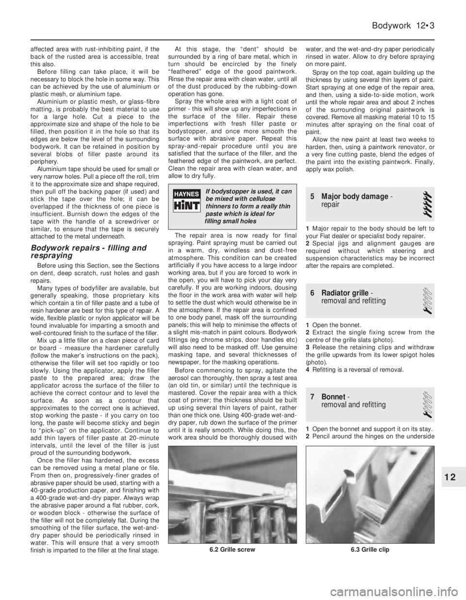
2Extract the single fixing screw from the
centre of the grille slats (photo).
3Release the retaining clips and withdraw
the grille upwards from its lower spigot holes
(photo).
4Refitting is a reversal of removal.
7 Bonnet-
removal and refitting
1
1Open the bonnet and support it on its stay.
2Pencil around the hinges on the underside
Bodywork 12•3
12
If bodystopper is used, it can
be mixed with cellulose
thinners to form a really thin
paste which is ideal for
filling small holes
6.3 Grille clip6.2 Grille screw
Page 118 of 303
10 Front wing-
removal and refitting
1
1Remove the headlamp and front parking
lamp as described in Chapter 9. 2Withdraw the side repeater lamp and
disconnect the leads.
3Remove the front roadwheel.
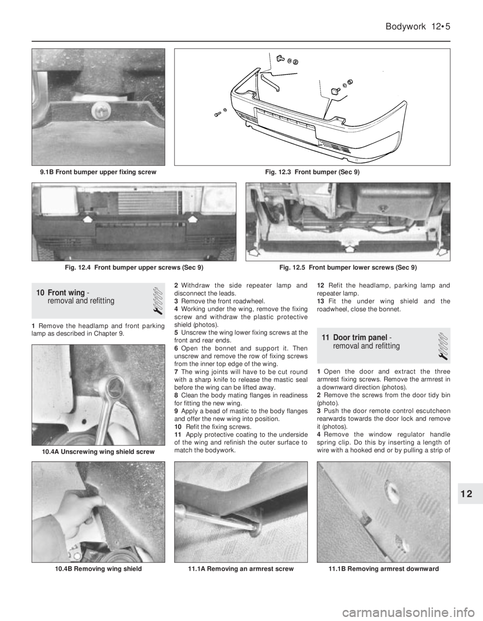
4Working under the wing, remove the fixing
screw and withdraw the plastic protective
shield (photos).
5Unscrew the wing lower fixing screws at the
front and rear ends.
6Open the bonnet and support it. Then
unscrew and remove the row of fixing screws
from the inner top edge of the wing.
7The wing joints will have to be cut round
with a sharp knife to release the mastic seal
before the wing can be lifted away.
8Clean the body mating flanges in readiness
for fitting the new wing.
9Apply a bead of mastic to the body flanges
and offer the new wing into position.
10Refit the fixing screws.
11Apply protective coating to the underside
of the wing and refinish the outer surface to
match the bodywork. 12Refit the headlamp, parking lamp and
repeater lamp.
13Fit the under wing shield and the
roadwheel, close the bonnet.
11 Door trim panel-
removal and refitting
1
1Open the door and extract the three
armrest fixing screws. Remove the armrest in
a downward direction (photos).
2Remove the screws from the door tidy bin
(photo).
3Push the door remote control escutcheon
rearwards towards the door lock and remove
it (photos).
4Remove the window regulator handle
spring clip. Do this by inserting a length of
wire with a hooked end or by pulling a strip of
Bodywork 12•5
Fig. 12.3 Front bumper (Sec 9)9.1B Front bumper upper fixing screw
11.1B Removing armrest downward11.1A Removing an armrest screw
10.4A Unscrewing wing shield screw
10.4B Removing wing shield
Fig. 12.4 Front bumper upper screws (Sec 9)Fig. 12.5 Front bumper lower screws (Sec 9)
12
Page 234 of 303
83Refitting is a reversal of the removal
procedure. Reset the clock on completion.
Central door locking system
84Certain later models, equipped with a
central door locking system, have an infra-red
remote control for opening the door locks.
85It is important that the battery used in the
hand control is renewed when necessary with
one of identical type (Duracell 7H34). This is
only available as a FIAT spare part (No
7595393).
86The remote control door lock receiver unit
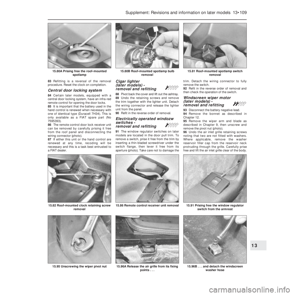
can be removed by carefully prising it free
from the roof panel and disconnecting the
wiring connector (photo).
87If either this unit or the hand control are
renewed at any time, recoding will be
necessary and this is a task best entrusted to
a FIAT dealer.
Cigar lighter
(later models) -
removal and refitting
Á
88Pivot back the cover and lift out the ashtray.
89Undo the retaining screws and remove
the trim together with the lighter unit. Detach
the wiring connector and release the lighter
unit from the panel.
90Refit in the reverse order of removal.
Electrically operated windozw
switches -
removal and refitting
Á
91The window regulator switches on later
models are located in the door pull trim. To
remove a switch, prise it free from the trim by
inserting a thin-bladed screwdriver under the
switch flange, then lever it free from its
aperture (photo). Take care not to damage thetrim. Detach the wiring connector to fully
remove the switch.
92Refit in the reverse order of removal and
then check the operation of the switch.
Windscreen wiper motor
(later models) -
removal and refitting
ª
93Disconnect the battery negative lead.
94Remove the bonnet as described in
Chapter 12.
95Remove the wiper arm and blade as
described in Chapter 9, then unscrew and
remove the pivot nut (photo).
96Undo the air inlet grille retaining screws
noting that two are not fitted with washers.
Where applicable, remove the washer
reservoir filler cap from the reservoir neck
protruding through the grille. Carefully prise
free and lift the air inlet grille clear of the body.
Supplement: Revisions and information on later models 13•109
15.81 Roof-mounted spotlamp switch
removal15.80B Roof-mounted spotlamp bulb
removal15.80A Prising free the roof-mounted
spotlamp
15.96B . . . and detach the windscreen
washer hose15.96A Release the air grille from its fixing
points . . .15.95 Unscrewing the wiper pivot nut
15.91 Prising free the window regulator
switch from the armrest15.86 Remote control receiver unit removal15.82 Roof-mounted clock retaining screw
removal
13
Page 235 of 303

As it is lifted, invert it and detach the washer
hose from the washer nozzle (photos).
97Where applicable, detach and remove the
washer reservoir from the recess in the front
of the windscreen to allow access to the wiper
motor.
98Unscrew and remove the two wiper motor
retaining screws. Lower and withdraw the
unit, then detach the cover from the motor.
Disconnect the wiring from the wiper motor
and withdraw it from the car (photos).
99Refit in the reverse order of removal.
Check for satisfactory operation of the wiper
and washer on completion.
Windscreen washer reservoir
(Turbo ie models) -
removal and refitting
Á
100Disconnect the battery negative lead.
101Remove the bonnet as described in
Chapter 12.
102Remove the wiper arm and blade as
described in Chapter 9, then unscrew and
remove the pivot nut.
103Undo the air inlet grille retaining screws
noting that two are not fitted with washers.
Where applicable, remove the washer
reservoir filler cap from the reservoir neck
protruding through the grille. Carefully prise
free and lift the air inlet grille clear of the body.
As it is lifted, invert it and detach the washer
hose from the washer nozzle.
104Syphon any remaining washer fluid from
the reservoir, then disconnect it and partiallywithdraw it from the recess in front of the
windscreen so that the wiring connection and
the washer supply hoses (to the windscreen
washer and the rear screen washer nozzles)
can be detached from the pump unit. Remove
the reservoir from the vehicle.
105Refit in the reverse order of removal. If the
washer pump unit was detached from the
reservoir, use a new seal washer when refitting
it. Top up the reservoir and check the screen
washers for satisfactory operation before
refitting the grille panel and the wiper arm/blade.
Tailgate wiper motor
(later models) -
removal and refitting
Á
106Although the tailgate wiper motor differs
in appearance, its removal and refitting
procedures are much the same as those
described for the earlier models in Section 27
of Chapter 9 (photo).
Radio
107All later models are now equipped with
power supply and speaker leads for radio
installation.
108Installation of the standard FIAT aerial
mounted on the windscreen pillar is shown
(photos).
Check control system sensors -
description
109The locations of the sensors referred to in
Chapter 9, Section 34 are given in the
following paragraphs, and their construction
differs according to their individual function.
Brake fluid level sensor
110This is mounted in the master cylinder
fluid reservoir cap, and comprises a pair of
reed switches in a glass bulb, and a magnet at
the end of a float.
111When the fluid level is correct, the
magnetic flux closes the switches. In the
event of a leak in the system, the magnet
moves away, the switches open and the
warning lamp comes on.
Brake disc pad wear sensor
112This is basically a circuit wire embedded
in the pad friction material. As the pad wears,
the wire is eventually exposed and contacts
the disc, whereupon the warning lamp comes
on to indicate that pad renewal is necessary.
Coolant level sensor
113This is located in the cooling system
expansion tank, and is of the reed switch
type, which operates in a similar way to that
described for the brake fluid sensor.
Engine oil level sensor
114This is located at the end of the dipstick,
and comprises a pair of switches at the end of a
bi-metallic strip, heated by electrical resistance.
115The heat is dissipated by the immersion
of the dipstick in the engine oil, so preventing
the bi-metallic strip from curving so much that
the switches would open.
116If the oil level drops, the heat is no longer
dissipated, the switches open, and the
warning lamp comes on.
13•110 Supplement: Revisions and information on later models
15.108B Pillar lower screw for aerial15.108A Pillar upper screws for aerial15.106 Tailgate wiper motor - later model
15.98C . . . and detach the wiring
connector15.98B . . . separate the wiper motor from
its cover . . .15.98A Remove the wiper motor retaining
screws . . .
Page 238 of 303
18Refitting of all components is a reversal of
removal.
Radiator grille (1301 cc
Turbo ie model) -
removal and refitting
Á
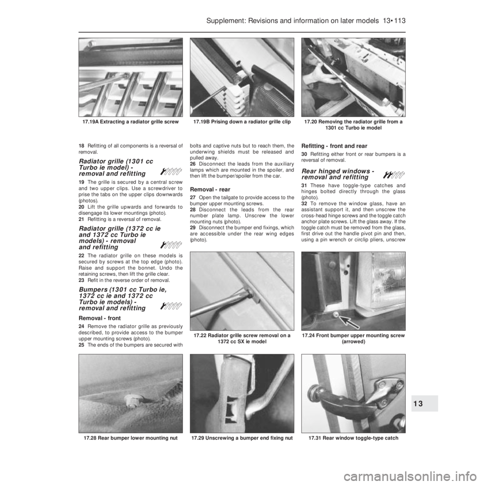
19The grille is secured by a central screw
and two upper clips. Use a screwdriver to
prise the tabs on the upper clips downwards
(photos).
20Lift the grille upwards and forwards to
disengage its lower mountings (photo).
21Refitting is a reversal of removal.
Radiator grille (1372 cc ie
and 1372 cc Turbo ie
models) - removal
and refitting
Á
22The radiator grille on these models is
secured by screws at the top edge (photo).
Raise and support the bonnet. Undo the
retaining screws, then lift the grille clear.
23Refit in the reverse order of removal.
Bumpers (1301 cc Turbo ie,
1372 cc ie and 1372 cc
Turbo ie models) -
removal and refitting
Á
Removal - front
24Remove the radiator grille as previously
described, to provide access to the bumper
upper mounting screws (photo).
25The ends of the bumpers are secured withbolts and captive nuts but to reach them, the
underwing shields must be released and
pulled away.
26Disconnect the leads from the auxiliary
lamps which are mounted in the spoiler, and
then lift the bumper/spoiler from the car.
Removal - rear
27Open the tailgate to provide access to the
bumper upper mounting screws.
28Disconnect the leads from the rear
number plate lamp. Unscrew the lower
mounting nuts (photo).
29Disconnect the bumper end fixings, which
are accessible under the rear wing edges
(photo).
Refitting - front and rear
30Refitting either front or rear bumpers is a
reversal of removal.
Rear hinged windows -
removal and refittingª
31These have toggle-type catches and
hinges bolted directly through the glass
(photo).
32To remove the window glass, have an
assistant support it, and then unscrew the
cross-head hinge screws and the toggle catch
anchor plate screws. Lift the glass away. If the
toggle catch must be removed from the glass,
first drive out the handle pivot pin and then,
using a pin wrench or circlip pliers, unscrew
Supplement: Revisions and information on later models 13•113
17.20 Removing the radiator grille from a
1301 cc Turbo ie model17.19B Prising down a radiator grille clip17.19A Extracting a radiator grille screw
17.31 Rear window toggle-type catch17.29 Unscrewing a bumper end fixing nut
17.24 Front bumper upper mounting screw
(arrowed)17.22 Radiator grille screw removal on a
1372 cc SX ie model
17.28 Rear bumper lower mounting nut
13
Page 295 of 303
Buying spare parts
Spare parts are available from many
sources, for example, FIAT garages, other
garages and accessory shops, and motor
factors. Our advice regarding spare parts is as
follows:
Officially appointed FIAT garages -This is
the best source of parts which are peculiar to
your car and otherwise not generally available
(eg complete cylinder heads, internal gearbox
components, badges, interior trim etc). It is
also the only place at which you should buy
parts if your vehicle is still under warranty;
non-FlAT components may invalidate the
warranty. To be sure of obtaining the correct
parts it will always be necessary to give the
partsman your car’s engine number, chassis
number and number for spares, and if
possible, to take the old part along for positive
identification. Many parts are available under
a factory exchange scheme - any parts
returned should always be clean. It obviously
makes good sense to go straight to the
specialists on your car for this type of part for
they are best equipped to supply you. They
will also be able to provide their own FIATservice manual for your car should you require
one.
Other garages and accessory shops - These
are often very good places to buy material
and components needed for the maintenance
of your car (eg oil filters, spark plugs, bulbs,
drivebelts, oils and grease, touch-up paint,
filler paste etc). They also sell accessories,
usually have convenient opening hours,
charge lower prices and can often be found
not far from home.
Motor factors - Good factors stock all of the
more important components which wear out
relatively quickly (eg clutch components,
pistons, valves, exhaust systems, brake
pipes/seals/shoes and pads etc). Motor
factors will often provide new or reconditioned
components on a part exchange basis - this
can save a considerable amount of money.
Vehicle identification
numbers
Modifications are a continuing and
unpublicised process in vehicle manufacture
quite apart from major model changes. Spareparts manuals and lists are compiled upon a
numerical basis, the individual vehicle
numbers being essential to correct identifi-
cation of the component required.
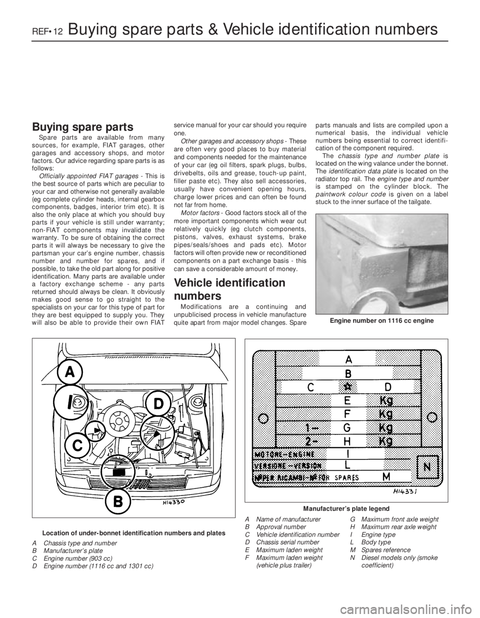
The chassis type and number plate is
located on the wing valance under the bonnet.
The identification data plate is located on the
radiator top rail. The engine type and number
is stamped on the cylinder block. The
paintwork colour code is given on a label
stuck to the inner surface of the tailgate.
REF•12Buying spare parts & Vehicle identification numbers
Manufacturer’s plate legend
Location of under-bonnet identification numbers and plates
A Chassis type and number
B Manufacturer’s plate
C Engine number (903 cc)
D Engine number (1116 cc and 1301 cc)
Engine number on 1116 cc engine
A Name of manufacturer
B Approval number
C Vehicle identification number
D Chassis serial number
E Maximum laden weight
F Maximum laden weight
(vehicle plus trailer)G Maximum front axle weight
H Maximum rear axle weight
I Engine type
L Body type
M Spares reference
N Diesel models only (smoke
coefficient)