1983 FIAT UNO engine
[x] Cancel search: enginePage 179 of 303
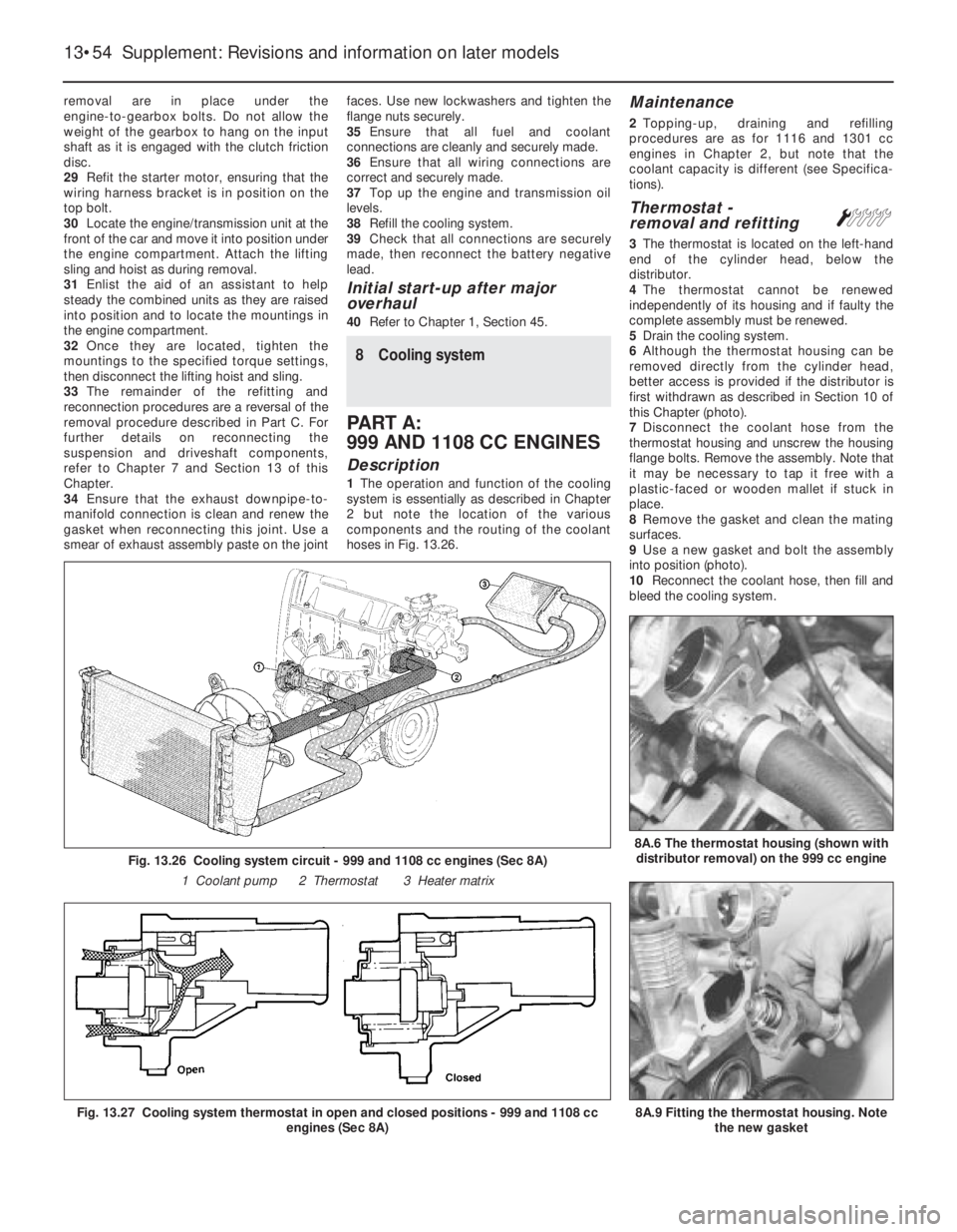
removal are in place under the
engine-to-gearbox bolts. Do not allow the
weight of the gearbox to hang on the input
shaft as it is engaged with the clutch friction
disc.
29Refit the starter motor, ensuring that the
wiring harness bracket is in position on the
top bolt.
30Locate the engine/transmission unit at the
front of the car and move it into position under
the engine compartment. Attach the lifting
sling and hoist as during removal.
31Enlist the aid of an assistant to help
steady the combined units as they are raised
into position and to locate the mountings in
the engine compartment.
32Once they are located, tighten the
mountings to the specified torque settings,
then disconnect the lifting hoist and sling.
33The remainder of the refitting and
reconnection procedures are a reversal of the
removal procedure described in Part C. For
further details on reconnecting the
suspension and driveshaft components,
refer to Chapter 7 and Section 13 of this
Chapter.
34Ensure that the exhaust downpipe-to-
manifold connection is clean and renew the
gasket when reconnecting this joint. Use a
smear of exhaust assembly paste on the jointfaces. Use new lockwashers and tighten the
flange nuts securely.
35Ensure that all fuel and coolant
connections are cleanly and securely made.
36Ensure that all wiring connections are
correct and securely made.
37Top up the engine and transmission oil
levels.
38Refill the cooling system.
39Check that all connections are securely
made, then reconnect the battery negative
lead.
Initial start-up after major
overhaul
40Refer to Chapter 1, Section 45.
8 Cooling system
PART A:
999 AND 1108 CC ENGINES
Description
1The operation and function of the cooling
system is essentially as described in Chapter
2 but note the location of the various
components and the routing of the coolant
hoses in Fig. 13.26.
Maintenance
2Topping-up, draining and refilling
procedures are as for 1116 and 1301 cc
engines in Chapter 2, but note that the
coolant capacity is different (see Specifica-
tions).
Thermostat -
removal and refittingÁ
3The thermostat is located on the left-hand
end of the cylinder head, below the
distributor.
4The thermostat cannot be renewed
independently of its housing and if faulty the
complete assembly must be renewed.
5Drain the cooling system.
6Although the thermostat housing can be
removed directly from the cylinder head,
better access is provided if the distributor is
first withdrawn as described in Section 10 of
this Chapter (photo).
7Disconnect the coolant hose from the
thermostat housing and unscrew the housing
flange bolts. Remove the assembly. Note that
it may be necessary to tap it free with a
plastic-faced or wooden mallet if stuck in
place.
8Remove the gasket and clean the mating
surfaces.
9Use a new gasket and bolt the assembly
into position (photo).
10Reconnect the coolant hose, then fill and
bleed the cooling system.
13•54 Supplement: Revisions and information on later models
Fig. 13.26 Cooling system circuit - 999 and 1108 cc engines (Sec 8A)
1 Coolant pump 2 Thermostat 3 Heater matrix
Fig. 13.27 Cooling system thermostat in open and closed positions - 999 and 1108 cc
engines (Sec 8A)8A.9 Fitting the thermostat housing. Note
the new gasket
8A.6 The thermostat housing (shown with
distributor removal) on the 999 cc engine
Page 180 of 303

Coolant pump -
removal and refitting#
11The coolant pump is located on the
crankshaft pulley end of the engine and is
driven by the timing belt.
12The pump cannot be repaired and must
be regarded as disposable.
13Drain the cooling system.
14Remove the timing belt cover and then set
No. 1 piston to TDC. To achieve this, turn the
crankshaft pulley bolt until the camshaft
sprocket timing mark is aligned with the one
on the cylinder head.
15Release the belt tensioner and slip the
timing belt off the camshaft and coolant pump
sprockets.
16Unbolt and remove the coolant pump and
clean the mounting face of all old gasket
material.
17Apply a continuous bead of RTV silicone
sealant (instant gasket) to the mounting face
of the coolant pump and bolt it into position
(photos).
18Check that the camshaft sprocket and the
crankshaft have not been moved and fit the
timing belt to the camshaft and coolant pump
sprockets. The pump sprocket does not
require setting in any particular position
before connecting the timing belt.
19Tension the belt as described in Sec-
tion 5B of this Chapter.
20Fit the timing belt cover.
21After allowing one hour for the gasket
material to cure, refill and bleed the cooling
system.
PART B:
1301 CC TURBO IE ENGINE
Description
1The cooling system on this model has flow
and return connections to the turbocharger,
and is an essential means of cooling the
turbocharger.
2The radiator cooling fan is of two-speed
type, being controlled by a two-stage
thermostatic switch screwed into the radiator
side tank.
3According to the coolant temperature level,
the fan speed is regulated to provide the most
effective cooling.
4The remote cooling system expansion tank
is mounted in the left-hand rear corner of the
engine compartment (photo).
PART C:
1372 CC IE AND 1372 CC
TURBO IE ENGINES
Description
1The cooling system layout and components
for the 1372 cc engines is shown in
Figs. 13.29 and 13.30.
2The system on each engine operates in
essentially the same manner as that
described for the other models in Chapter 2,
but the location of components and the
coolant hose routings differ according to
model. The cooling system expansion tank
location differs according to model, being
either located on the side of the radiator ormounted separately on the side of the inner
wing panel.
3On Turbo models, the cooling system also
assists in cooling the turbocharger.
Maintenance
4The maintenance procedures are
essentially the same as those described for
the other models in Chapter 2.
Cooling system - draining,
flushing and refillingÁ
Warning: Wait until the engine is
cold before starting this
procedure. Do not allow
antifreeze to come into contact
with your skin or painted surfaces of the
vehicle. Rinse off spills immediately with
plenty of water. Never leave antifreeze
lying around in an open container or in a
puddle in the driveway or on the garage
floor. Children and pets are attracted by its
sweet smell. Antifreeze is fatal if ingested.
5Disconnect the battery negative lead.
6Working inside the vehicle, turn the heater
temperature control knob fully to the right,
which will fully open the heater coolant valve.
7With the expansion tank cap removed,
place a suitable container beneath the
radiator bottom hose.
8Loosen the clip and ease the bottom hose
away from the radiator outlet (photo). Allow
the coolant to drain into the container.
9Reposition the container under the front of
the cylinder block, and unscrew the cylinder
block drain plug (photo). Allow the coolant to
drain into the container.
Supplement: Revisions and information on later models 13•55
8A.17B Tightening the coolant pump bolts8A.17A Fitting the coolant pump to the
999 cc engineFig. 13.28 Sectional view of the coolant
pump on the 999 and 1108 cc engines
(Sec 8A)
8C.9 Cylinder block drain plug8C.8 Bottom hose connection to the
radiator8B.4 Topping up the expansion tank with
antifreeze on the 1301 cc engine
13
Page 181 of 303
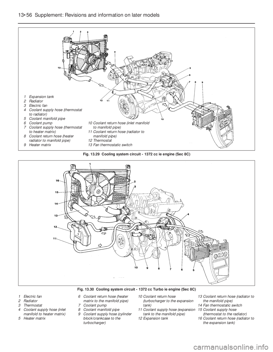
1 Electric fan
2 Radiator
3 Thermostat
4 Coolant supply hose (inlet
manifold to heater matrix)
5 Heater matrix6 Coolant return hose (heater
matrix to the manifold pipe)
7 Coolant pump
8 Coolant manifold pipe
9 Coolant supply hose (cylinder
block/crankcase to the
turbocharger)10 Coolant return hose
(turbocharger to the expansion
tank)
11 Coolant supply hose (expansion
tank to the manifold pipe)
12 Expansion tank13 Coolant return hose (radiator to
the manifold pipe)
14 Fan thermostatic switch
15 Coolant supply hose
(thermostat to the radiator)
16 Coolant return hose (radiator to
the expansion tank)
13•56 Supplement: Revisions and information on later models
Fig. 13.29 Cooling system circuit - 1372 cc ie engine (Sec 8C)
Fig. 13.30 Cooling system circuit - 1372 cc Turbo ie engine (Sec 8C)
1 Expansion tank
2 Radiator
3 Electric fan
4 Coolant supply hose (thermostat
to radiator)
5 Coolant manifold pipe
6 Coolant pump
7 Coolant supply hose (thermostat
to heater matrix)
8 Coolant return hose (heater
radiator to manifold pipe)
9 Heater matrix10 Coolant return hose (inlet manifold
to manifold pipe)
11 Coolant return hose (radiator to
manifold pipe)
12 Thermostat
13 Fan thermostatic switch
Page 182 of 303
10Apply suitable sealant to the threads of
the drain plug, then refit and tighten the plug.
11Dispose of the drained coolant safely, or
keep it in a covered container if it is to be
re-used.
12If required, the system can be flushed
through as described in Section 2 of Chap-
ter 2.
13Before attempting to refill the cooling
system, make sure that all hoses have been
reconnected, that the hoses and clips are in
good condition, and that the clips are tight.
Also ensure that the cylinder block drain plug
has been refitted and tightened. Note that an
antifreeze mixture must be used all year round
to prevent corrosion of the engine
components - refer to Section 3, Chapter 2.
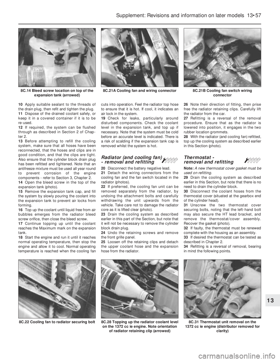
14Open the bleed screw in the top of the
expansion tank (photo).
15Remove the expansion tank cap, and fill
the system by slowly pouring the coolant into
the expansion tank to prevent air locks from
forming.
16Top up the coolant until liquid free from air
bubbles emerges from the radiator bleed
screw orifice, then close the bleed screw.
17Continue topping up until the coolant
reaches the Maximum mark on the expansion
tank.
18Start the engine and run it until it reaches
normal operating temperature, then stop the
engine and allow it to cool. Normal operating
temperature is reached when the cooling fancuts into operation. Feel the radiator top hose
to ensure that it is hot. If cool, it indicates an
air lock in the system.
19Check for leaks, particularly around
disturbed components. Check the coolant
level in the expansion tank, and top up if
necessary. Note that the system must be cold
before an accurate level is indicated. There is
a risk of scalding if the expansion tank cap is
removed whilst the system is hot.
Radiator (and cooling fan)
- removal and refitting Á
20Disconnect the battery negative lead.
21Detach the wiring connectors from the
cooling fan and the fan switch located in the
radiator (photos).
22If preferred, the cooling fan unit can be
removed separately from the radiator, by
undoing the attachment bolts and carefully
withdrawing the unit upwards from the
vehicle. Take care not to damage the radiator
core as it is lifted clear (photo).
23Drain the cooling system as described
earlier in this part of the Section, but note that
it will not be necessary to remove the cylinder
block drain plug.
24Undo the retaining screws and remove
the front grille panel.
25Loosen off the retaining clips and detach
the upper coolant hose and the expansion
hose from the radiator.26Note their direction of fitting, then prise
free the radiator retaining clips. Carefully lift
the radiator from the car.
27Refitting is a reversal of the removal
procedure. Ensure that as the radiator is
lowered into position, it engages in the two
rubber location grommets.
28With the radiator (and cooling fan) refitted,
top up the cooling system as described earlier
in this Section (photo).
Thermostat -
removal and refitting Á
Note: A new thermostat cover gasket must be
used on refitting.
29Drain the cooling system as described
earlier in this Section, but note that there is no
need to drain the cylinder block.
30Disconnect the coolant hoses from the
thermostat cover (situated at the gearbox end
of the cylinder head).
31Unscrew the two thermostat cover
securing bolts, noting that the left-hand bolt
may also secure the HT lead bracket, and
remove the thermostat/cover assembly.
Recover the gasket (photo).
32If faulty, the thermostat must be renewed
complete with the housing as an assembly.
33If desired the thermostat can be tested as
described in Chapter 2.
34Refitting is a reversal of removal, bearing
in mind the following points.
Supplement: Revisions and information on later models 13•57
8C.21B Cooling fan switch wiring
connector8C.21A Cooling fan and wiring connector8C.14 Bleed screw location on top of the
expansion tank (arrowed)
8C.31 Thermostat unit removal on the
1372 cc ie engine (distributor removed for
clarity)8C.28 Topping up the radiator coolant level
on the 1372 cc ie engine. Note orientation
of radiator retaining clip (arrowed)8C.22 Cooling fan to radiator securing bolt
13
Page 183 of 303

35Clean the mating faces of the thermostat
cover and cylinder head, and use a new
gasket when refitting the cover.
36Refill the cooling system as described
earlier in this Section.
Coolant pump -
removal and refittingÁ
Note: A new coolant pump gasket must be
used on refitting. If the pump is found to be
worn it must be renewed as a complete unit as
dismantling and repair is not possible.
37Disconnect the battery negative lead.
38Drain the cooling system as described
earlier in this Section.
39Remove the coolant/alternator drivebelt
as described in the next sub-Section.
40Unscrew the four coolant pump securing
bolts, noting that two of the bolts also secure
the alternator adjuster bracket, and withdraw
the pump from the housing (photo). Recover
the gasket.
41Refitting is a reversal of removal, bearing
in mind the following points.
42Use a new gasket between the pump and
the housing.
43Refit and tension the coolant
pump/alternator drivebelt as described in the
next sub-Section.
44On completion, refill the cooling system
as described earlier in this Section.
Coolant pump/alternator
drivebelt - checking,
renewal and tensioning
Á
45At the intervals specified in Section 3 or
“Routine maintenance” at the beginning of
this manual (as applicable), the drivebelt
should be checked and if necessary
re-tensioned.
46Access to the drivebelt is made from the
underside of the car on the right-hand side.
Loosen off the front right-hand roadwheel
retaining bolts, then raise and support the car
on axle stands at the front. Remove the front
roadwheel on the right-hand side.
47Remove the underwing shield from the
right-hand wheel arch by drifting the
compression pins out from the retaining
clips. Prise free the clips and remove the
shield.
48Additional, though somewhat restricted,
access can be obtained from above by
removing the air cleaner unit on the non-Turbo
ie-engine (photo).
49Check the full length of the drivebelt for
cracks and deterioration. It will be necessary
to turn the engine in order to check the
portions of the drivebelt in contact with the
pulleys. If a drivebelt is unserviceable, renew it
as follows (photo).
50Loosen the alternator mounting and
adjuster nuts and bolts and pivot the
alternator towards the cylinder block.51Slip the drivebelt from the alternator,
coolant pump and crankshaft pulleys.
52Fit the new drivebelt around the pulleys,
then lever the alternator away from the
cylinder block until the specified belt tension
is achieved. Lever the alternator using a
wooden or plastic lever at the pulley end to
prevent damage. It is helpful to partially
tighten the adjuster nut before tensioning the
drivebelt (photo).
53When the specified tension has been
achieved, tighten the mounting and adjuster
nuts and bolts (photo).
PART D: HEATER UNIT- LATER
MODELS
Heater unit -
removal and refitting
Á
1The heater unit is removed complete with
the facia/control panel. Commence by
draining the cooling system as described
previously in this Section.
2Disconnect the battery negative lead.
3Refer to Section 15 of this Chapter for
details and remove the ashtray/cigar lighter
and the auxiliary control panel.
4Undo the upper screw retaining the heater
unit to the facia (see Fig. 13.31).
5Remove the radio from the central facia.
6Undo the retaining screw on each side at
the front of the gear lever console. Prise free
13•58 Supplement: Revisions and information on later models
Fig. 13.31 Removing the heater unit-to-
facia upper retaining screw (Sec 8D)8C.53 Tightening the alternator adjuster
nut8C.52 Fitting a new coolant
pump/alternator drivebelt around the
pulleys
8C.49 Alternator/water pump drivebelt and
tensioner viewed from the right-hand
wheel arch8C.48 Top side view of water pump,
alternator and drivebelt8C.40 Coolant pump/alternator bracket
bolt removal
Page 185 of 303
9 Fuel and exhaust systems
Warning: Many of the
procedures in this Section
require the removal of fuel lines
and connections that may result
in some fuel spillage. Before carrying out
any operation on the fuel system refer to
the precautions given in ‘Safety first!’ at
the beginning of this Manual and follow
them implicitly. Petrol is a highly
dangerous and volatile liquid, and the
precautions necessary when handling it
cannot be overstressed.
Caution: On fuel injection
models, the system is
pressurised, therefore extra
care must be taken when
disconnecting fuel lines. When
disconnecting a fuel line union, loosen the
union slowly, to avoid a sudden release of
pressure that may cause fuel to spray out
and have a container and cloth ready to
catch spillages. Fuel pressure checking
must be entrusted to a Fiat dealer, or other
specialist, who has the necessary special
equipment.
PART A: GENERAL
Unleaded fuel
Note: On models with catalytic convertersonly unleaded petrol must be used - the use
of leaded petrol will destroy the catalyst.
1It is possible to use unleaded fuel (minimum
95 RON) in the following models with the
indicated serial numbers.
Engine Serial number
903 cc 146A.000
146A.046
146A.048
999 cc 156A2.00
1108 cc 160A3.000
1116 cc 138B.000
138B.046
146A4000
146A4.048
1299/1301 cc 138B2.000
138B2.046
149A7.000
1149A7.000
146A2.000
1372 cc 146C1.000
146A8.000
160A1.046
2On all except the 903 cc engine, the use of
unleaded fuel is conditional upon the
avoidance of constant high speeds and
sudden acceleration.
Air cleaner - modified types
3The air cleaner on later models is of the
automatic temperature controlled type. The
need to move the intake control lever to winter
or summer positions is no longer required.
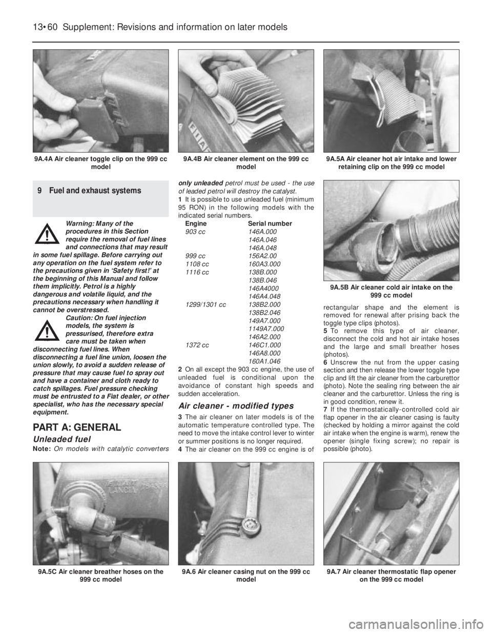
4The air cleaner on the 999 cc engine is ofrectangular shape and the element is
removed for renewal after prising back the
toggle type clips (photos).
5To remove this type of air cleaner,
disconnect the cold and hot air intake hoses
and the large and small breather hoses
(photos).
6Unscrew the nut from the upper casing
section and then release the lower toggle type
clip and lift the air cleaner from the carburettor
(photo). Note the sealing ring between the air
cleaner and the carburettor. Unless the ring is
in good condition, renew it.
7If the thermostatically-controlled cold air
flap opener in the air cleaner casing is faulty
(checked by holding a mirror against the cold
air intake when the engine is warm), renew the
opener (single fixing screw); no repair is
possible (photo).
13•60 Supplement: Revisions and information on later models
9A.7 Air cleaner thermostatic flap opener
on the 999 cc model9A.6 Air cleaner casing nut on the 999 cc
model9A.5C Air cleaner breather hoses on the
999 cc model
9A.5B Air cleaner cold air intake on the
999 cc model
9A.5A Air cleaner hot air intake and lower
retaining clip on the 999 cc model9A.4B Air cleaner element on the 999 cc
model9A.4A Air cleaner toggle clip on the 999 cc
model
Page 186 of 303
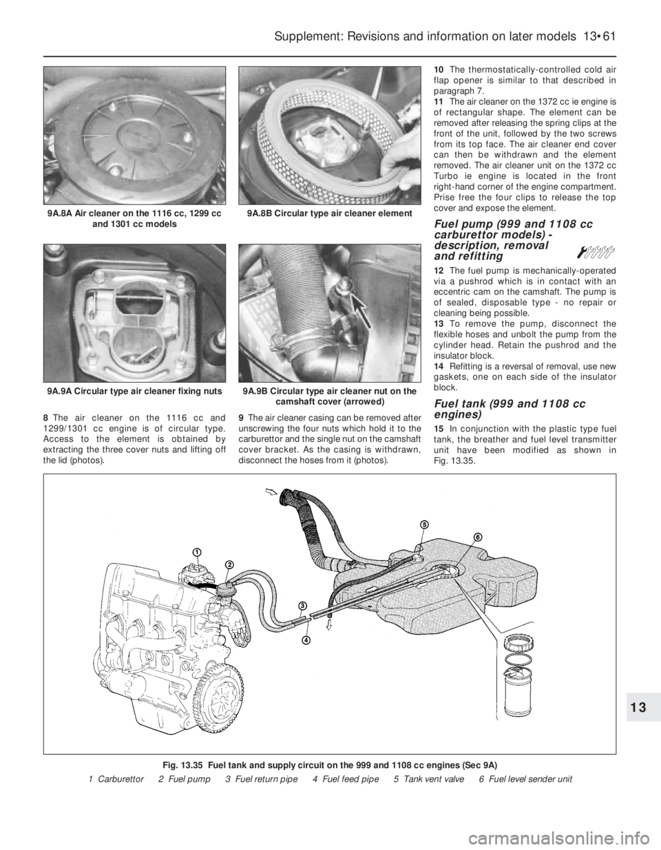
8The air cleaner on the 1116 cc and
1299/1301 cc engine is of circular type.
Access to the element is obtained by
extracting the three cover nuts and lifting off
the lid (photos).9The air cleaner casing can be removed after
unscrewing the four nuts which hold it to the
carburettor and the single nut on the camshaft
cover bracket. As the casing is withdrawn,
disconnect the hoses from it (photos).10The thermostatically-controlled cold air
flap opener is similar to that described in
paragraph 7.
11The air cleaner on the 1372 cc ie engine is
of rectangular shape. The element can be
removed after releasing the spring clips at the
front of the unit, followed by the two screws
from its top face. The air cleaner end cover
can then be withdrawn and the element
removed. The air cleaner unit on the 1372 cc
Turbo ie engine is located in the front
right-hand corner of the engine compartment.
Prise free the four clips to release the top
cover and expose the element.
Fuel pump (999 and 1108 cc
carburettor models) -
description, removal
and refitting
Á
12The fuel pump is mechanically-operated
via a pushrod which is in contact with an
eccentric cam on the camshaft. The pump is
of sealed, disposable type - no repair or
cleaning being possible.
13To remove the pump, disconnect the
flexible hoses and unbolt the pump from the
cylinder head. Retain the pushrod and the
insulator block.
14Refitting is a reversal of removal, use new
gaskets, one on each side of the insulator
block.
Fuel tank (999 and 1108 cc
engines)
15In conjunction with the plastic type fuel
tank, the breather and fuel level transmitter
unit have been modified as shown in
Fig. 13.35.
Supplement: Revisions and information on later models 13•61
9A.9A Circular type air cleaner fixing nuts9A.9B Circular type air cleaner nut on the
camshaft cover (arrowed)
9A.8B Circular type air cleaner element9A.8A Air cleaner on the 1116 cc, 1299 cc
and 1301 cc models
Fig. 13.35 Fuel tank and supply circuit on the 999 and 1108 cc engines (Sec 9A)
1 Carburettor 2 Fuel pump 3 Fuel return pipe 4 Fuel feed pipe 5 Tank vent valve 6 Fuel level sender unit
13
Page 187 of 303
PART B:
CARBURETTOR MODELS
Carburettor (Weber 32 TLF) -
description
Warning: Refer to the beginning
of this Section before starting
any work.
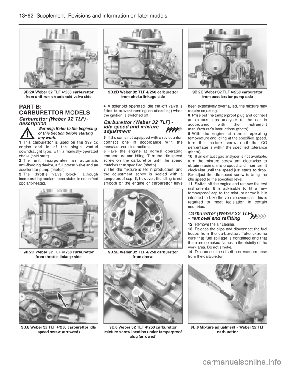
1This carburettor is used on the 999 cc
engine and is of the single venturi
downdraught type, with a manually-operated
choke (cold start).
2The unit incorporates an automatic
anti-flooding device, a full power valve and an
accelerator pump (photos).
3The throttle valve block, although
incorporating coolant hose stubs, is not in fact
coolant-heated.4A solenoid-operated idle cut-off valve is
fitted to prevent running-on (dieseling) when
the ignition is switched off.
Carburettor (Weber 32 TLF) -
idle speed and mixture
adjustment
¢
5If the car is not equipped with a rev counter,
connect one in accordance with the
manufacturer’s instructions.
6Have the engine at normal operating
temperature and idling. Turn the idle speed
screw on the carburettor until the speed
matches that specified (photo).
7The idle mixture is set in production, and
the adjustment screw is sealed with a
tamperproof cap. If, however, the idling is not
smooth or the engine or carburettor havebeen extensively overhauled, the mixture may
require adjusting.
8Prise out the tamperproof plug and connect
an exhaust gas analyser to the car in
accordance with the instrument
manufacturer’s instructions (photo).
9With the engine at normal operating
temperature and idling at the specified speed,
turn the mixture screw until the CO
percentage is within the specified tolerance
(photo).
10If an exhaust gas analyser is not available,
turn the mixture screw anti-clockwise to
obtain maximum idle speed and then turn it
clockwise until the speed just starts to drop.
Re-adjust the idle speed screw to bring the
idle speed to the specified level.
11Switch off the engine and remove the test
instruments. It is advisable to fit a new
tamperproof cap to the mixture screw if it is
intended to take the vehicle overseas. This is
required to meet legislation in certain
countries.
Carburettor (Weber 32 TLF)
- removal and refitting ª
12Remove the air cleaner.
13Release the clips and disconnect the fuel
hoses from the carburettor. Take extreme
care that fuel spillage is contained and that
there are no naked flames in the vicinity of the
work area. Do not smoke.
14Disconnect the distributor vacuum hose
from the carburettor.
13•62 Supplement: Revisions and information on later models
9B.9 Mixture adjustment - Weber 32 TLF
carburettor9B.8 Weber 32 TLF 4/250 carburettor
mixture screw location under tamperproof
plug (arrowed)9B.6 Weber 32 TLF 4/250 carburettor idle
speed screw (arrowed)
9B.2E Weber 32 TLF 4/250 carburettor
from above9B.2D Weber 32 TLF 4/250 carburettor
from throttle linkage side
9B.2C Weber 32 TLF 4/250 carburettor
from accelerator pump side9B.2B Weber 32 TLF 4/250 carburettor
from choke linkage side9B.2A Weber 32 TLF 4/250 carburettor
from anti-run-on solenoid valve side