1982 CHEVROLET CAMARO air condition
[x] Cancel search: air conditionPage 690 of 875

GM – CAMARO 1982-1992 – Repair Guide (Checked by WxMax) 690
b. Install plug, with hollow end do
wn, over the rich mixture stop
screw access hole and drive plug into place so that the top of the
plug is
3/16 in. (4.7mm) below the surface of the air horn casting.
Plug must be installed to retain screw setting.
12. To check the M/C solenoid dwell, first disconnect vacuum line to the
canister purge valve and plug it. Ground diagnostic TEST terminal and
run engine until it is at normal operat ion temperature (upper radiator
hose hot) and in closed loop.
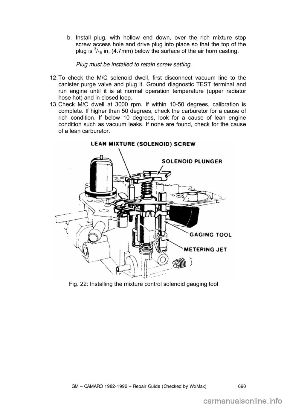
13. Check M/C dwell at 3000 rpm. If within 10-50 degrees, calibration is
complete. If higher than 50 degrees, chec k the carburetor for a cause of
rich condition. If below 10 degrees, look for a cause of lean engine
condition such as vacuum leaks. If none are found, check for the cause
of a lean carburetor.
Fig. 22: Installing the mixture control solenoid gauging tool
Page 698 of 875

GM – CAMARO 1982-1992 – Repair Guide (Checked by WxMax) 698
5. Disconnect and plug hose to canister purge port.
6. Disconnect and plug hose to idle load compensator.
7. Back out idle stop screw
on carburetor 3 turns.
8. Turn air conditioning OFF.
9. Block drive wheels, set parki ng brake, place transmission in P, start and
warm engine to normal operating temperature. Make certain choke is
OPEN .
10. With engine RUNNING place transmission in D and idle load
compensator fully extended (no vacuum applied). Using tool J-29607, or
equivalent, adjust plunger to obtain 650-750 rpm. Locknut on plunger
must be held with a wrench to prevent damage to guide tabs.
11. Measure distance from the locknut to tip of the plunger. This distance
must not exceed 1 in. (25mm). If it does check for low idle condition.
12. Reconnect vacuum hose to idle load compensator and observe idle
speed.
13. Idle speed should be between 425-475 rpm in D.
14. If idle speed is correct no further adjustment is necessary, proceed to the
next step. If idle speed is still incorrect continue as follows:
It may be necessary to remove the idle load compensator from the engine
unless a hex key wrench is m odified to clear obstructions.
a. Stop engine, remove rubber cap from the center outlet tube.
b. Using a 0.90 in. (23mm) hex wrench, insert through open center tube to
engage idle speed adjusting screw.
c. If idle speed was low, turn t he adjusting screw counterclockwise
approximately 1 turn for every 85 rpm low. If idle speed was high turn
screw 1 turn for every 85 rpm high.
15. Disconnect and plug vacuum hose to the idle load compensator.
16. Using a hand pump, apply vacuum to the idle load compensator until fully
retracted.
17. Adjust the idle stop screw on carburetor float bowl to obtain 450 rpm in
D .
18. Place transmission in P and stop engine.
19. Reconnect the idle load compensator.
20. Reconnect all vacuum hoses.
21. Install air cleaner and gasket. Remove wheel blocks.
Page 709 of 875

GM – CAMARO 1982-1992 – Repair Guide (Checked by WxMax) 709
passages, or air bleeds. Clean all jets and va
lves separately to avoid accidental
interchange.
Check all parts for wear or damage. If we ar or damage is found, replace the
defective parts. Especially check the following:
1. Check the float needle and seat for wear.
2. Check the float hinge pin for wear and the float(s) for dents or distortion.
Replace the float if fuel has leaked into it.
3. Check the throttle and choke sha ft bores for wear or an out-of-round
condition. Damage or wear to the thro ttle arm, shaft, or shaft bore will
often require replacement of the throttle body. These parts require a
close tolerance of fit; wear may allow air leakage, which could affect
starting and idling.
Throttle shafts and bushings are not included in overhaul kits. They can be
purchased separately or repaired by a qualified carburetor overhaul shop.
4. Inspect the idle mixt ure adjusting needles for bu rrs or grooves. Any such
condition requires replacement of t he needle, since you will not be able
to obtain a satisfactory idle.
5. Test the accelerator pump check va lves. They should pass air one way
but not the other. Test for proper s eating by blowing and sucking on the
valve. Replace the valve check ball and spring as necessary. If the valve
is satisfactory, wash the valve part s again to remove breath moisture.
6. Check the bowl cover for war ped surfaces with a straightedge.
7. Closely inspect the accelerato r pump plunger for wear and damage,
replacing as necessary.
8. After the carburetor is assembled, check the choke valve for freedom of
operation.
9. Check, repair or replace parts, if the following problems are encountered:
FLOODING
• Inspect the float valve and seat for dirt, deep wear grooves, scores and
improper sealing
• Inspect the float valve pull clip for proper installation; be careful no\
t to
bend the pull clip
• Inspect the float, the float arms and the hinge pin for distortion, binds,
and burrs. Check the density of the mate rial in the float; if heavier than
normal, replace the float
• Clean or replace the fuel inlet f ilter and check the valve assembly
HESITATION
• Inspect the pump plunger for cracks, scores or cup excessive wear. A
used pump cup will shrink w hen dry. If dried out, soak in fuel for 8 hours
before testing
• Inspect the pump duration and return springs for weakness or distortion \
Page 710 of 875

GM – CAMARO 1982-1992 – Repair Guide (Checked by WxMax) 710
•
Check the pump passages and the jet(s) for dirt, improper seating of the
discharge checkball or t he temperature bypass disc and/or scores in the
pumpwell. Check the condition of t he pump discharge check ball spring,
replace as necessary
• Check the pump linkage for excessiv e wear; repair or replace as
necessary
HARD STARTING-POOR COLD OPERATION
• Check the choke valve and linkage for excessive wear, binds or
distortion
• Test the vacuum break diaphragm(s) for leaks
• Clean or replace the fuel filter
• Inspect the float valve fo r sticking, dirt, etc.
• Also check the items under "Flooding"
POOR PERFORMANCE-POOR GAS MILEAGE
• Clean all fuel and vacuum passages in the castings
• Check the choke valve fo r freedom of movement
• Check the Mixture Control (M/C) soleno id for sticking, binding or leaking
• Check the air valve and secondary me tering rod for binding conditions. If
the air valve or metering rod is da maged or the metering rod adjustment
is changed from the factory setting, the air horn assembly must be
replaced. Also check the air valve le ver spring for proper installation
ROUGH IDLE
• Inspect the gasket and gasket mating su rfaces on the casting for nicks,
burrs or damage to the sealing beads
• Check the operation and sealing of the mixture control solenoid
• Clean all of the idle field passages
• If removed, inspect the idle mixture needle for ridges, burrs or being bent
• Check the throttle lever and valves for binds, nicks. or other damage
• Check all of the diaphragms for possible ruptures or leaks
After cleaning and checking all components, reassemble the carburetor, using
new parts and referring to the exploded view. When reassembling, make sure
that all screws and jets are tight in their seats, but do not overtighten as the tips
will be distorted. Tighten al l screws gradually, in rotation. Do not tighten needle
valves into their seats; uneven jetting will result. Always use new gaskets. Be
sure to follow all assembly and adjustment procedures.
Before performing any service on the carburet or, it is essential that it be placed
on a suitable holding fixtur e, such as tool J-9789-118, BY-30-15 or equivalent.
Without the use of the holding fixture, it is possible to damage throttle valves or
other parts of the carburetor.
Page 735 of 875

GM – CAMARO 1982-1992 – Repair Guide (Checked by WxMax) 735
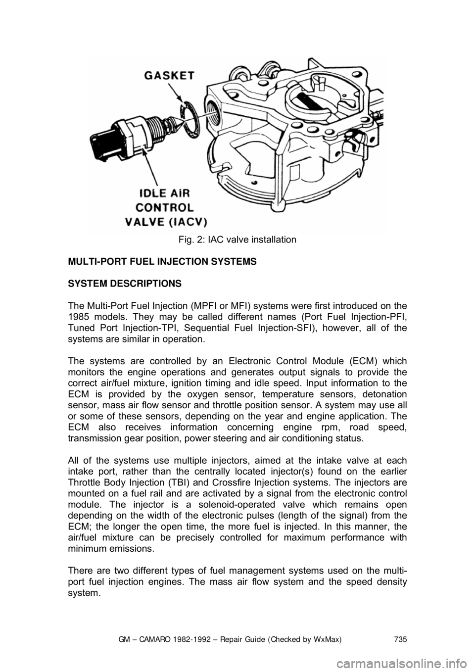
Fig. 2: IAC valve installation
MULTI-PORT FUEL INJECTION SYSTEMS
SYSTEM DESCRIPTIONS
The Multi-Port Fuel Injection (MPFI or MFI) systems were first introduced on the
1985 models. They may be called different names (Port Fuel Injection-PFI,
Tuned Port Injection-TPI, Sequential Fuel Injection-SFI), however, all of the
systems are similar in operation.
The systems are controlled by an Elec tronic Control Module (ECM) which
monitors the engine operations and gen erates output signals to provide the
correct air/fuel mixture, ignition timing and idle speed. Input information to the
ECM is provided by the oxygen sens or, temperature sensors, detonation
sensor, mass air flow sensor and throttle position sensor. A system may use all
or some of these sensors, depending on the year and engine application. The
ECM also receives information concerning engine rpm, road speed,
transmission gear position, power steer ing and air conditioning status.
All of the systems use multiple injector s, aimed at the intake valve at each
intake port, rather than the centrally lo cated injector(s) found on the earlier
Throttle Body Injection (TBI) and Crossfir e Injection systems. The injectors are
mounted on a fuel rail and ar e activated by a signal from the electronic control
module. The injector is a solenoi d-operated valve which remains open
depending on the width of t he electronic pulses (length of the signal) from the
ECM; the longer the open time, the more f uel is injected. In this manner, the
air/fuel mixture can be precisely c ontrolled for maximum performance with
minimum emissions.
There are two different types of f uel management systems used on the multi-
port fuel injection engines. The mass air flow system and the speed density
system.
Page 743 of 875

GM – CAMARO 1982-1992 – Repair Guide (Checked by WxMax) 743
MINIMUM IDLE SPEED
The minimum idle speed should onl
y be adjusted under two conditions:
If the throttle body has been replaced.
After every other possible cause for the in correct idle speed has been explored.
There are many possible causes for incorre ct idle speed, most of which require
a high level of diagnostic skill as well as expensive testing equipment. Check
the vehicle for vacuum leaks, incorrect valve or ignition timing, deposit
accumulation in the throttle bore or valve, sticking throttle linkage or bent throttle
valves. If the vehicle will still not idle pr operly after checking these areas, it
should be diagnosed by a professional.
1. Pierce the idle stop screw with an awl. Apply leverage to remove it.
2. Make sure the IAC valve is connect ed. Short the A and B terminals of the
ALDL connector together with a length of wire.
3. Turn the ignition to the ON positi on, but do not start the engine. Wait at
least 30 seconds before proceeding.
4. With the ignition ON, disconnect the IAC valve connector.
5. Separate the set-timing connector. Th is eliminates the possibility of
changes in engine speed due to variations of engine timing.
6. Start the engine and remove t he wire shorting the A and B terminals
together. It may be necessary to hold the throttle open slightly to prevent
the engine from stalling.
7. Allow the engine to reach no rmal operating temperature.
8. Adjust the idle speed to the following: a. 2.8L Engines - 450-550 rp m A/T or 550-650 rpm M/T
b. 3.1L Engines - Refer to the underhood emissions sticker
c. 5.0L and 5.7L TPI engines - 400-450 rpm.
If these figures differ from t hose on the underhood emissions
sticker, always follow the specifications on the emissions sticker.
9. Turn the ignition OFF and connect the IAC valve harness. On models up
to 1989, adjust the Throttle Position Sensor.
THROTTLE POSITION SENSOR (TPS) 1. Install three jumper wires betw een the TPS and the harness connector.
2. Use a digital voltmeter connected to terminals A and B of the TPS.
3. Turn the ignition switch ON , but do not start the engine.
4. Loosen the TPS attaching screws and adj ust the sensor to the following:
a. 2.8L Engines - 0.50-0.60 volts
b. 5.0L and 5.7L TPI Engines - 0.47-0.61 volts
5. Tighten the attaching screws, then check that the reading has not been
disturbed.
6. With the ignition OFF, remove the jumper wires. Reconnect the TPS
harness.
Page 772 of 875

GM – CAMARO 1982-1992 – Repair Guide (Checked by WxMax) 772
Special tools can usually be purchased fr
om an automotive parts store or from
your dealer. In some cases special tools may be available directly from the tool
manufacturer.
SERVICING YOUR VEHICLE SAFELY
It is virtually impossible to anticipate all of the hazards involved with automotive
maintenance and service, but care and common sense will prevent most
accidents.
The rules of safety for mechanics range fr om "don't smoke around gasoline," to
"use the proper tool(s) for the job." The tr ick to avoiding injuries is to develop
safe work habits and to take every possible precaution.
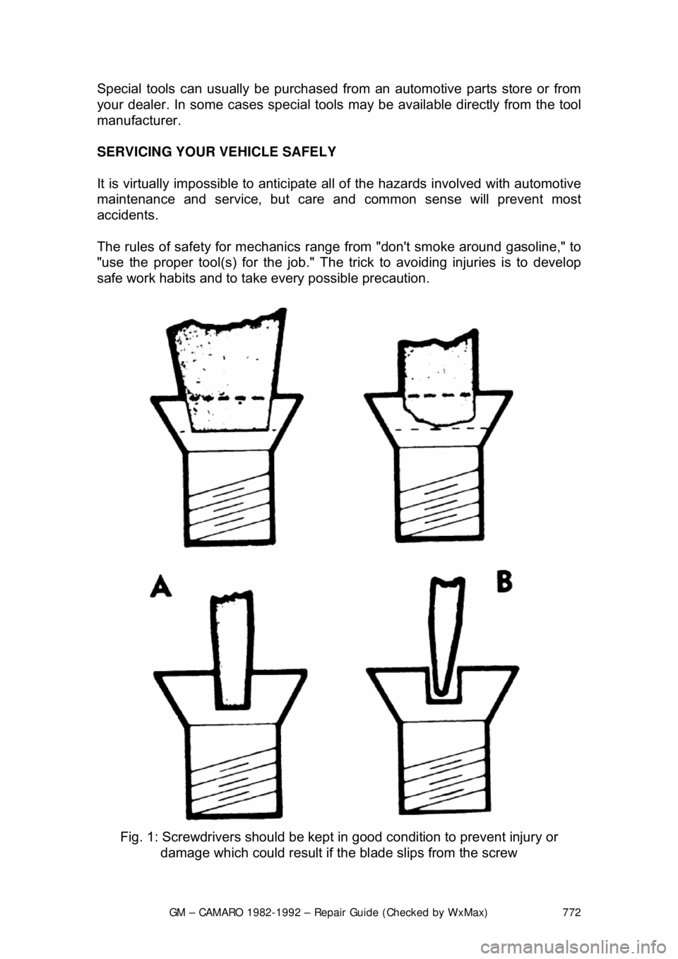
Fig. 1: Screwdrivers should be kept in good condition to prevent injury \
or
damage which could result if t he blade slips from the screw
Page 779 of 875

GM – CAMARO 1982-1992 – Repair Guide (Checked by WxMax) 779
ENGINE OIL AND FILTER CHANGE
Under normal operating conditions, the oi
l is to be changed every 7,500 miles
(12,000km) or 12 months, whichever occurs first.
Although the manufacturer recommends changing the f ilter at the first oil
change and then at every other oil c hange, (unless 12 months pass between
changes), The editors of this informat ion recommend changing the filter with
each service. It is a small price to pay for extra protection.
When driving conditions frequently include dusty or polluted areas, trailer
towing, idling for long periods of ti me, or low speed operation, or when
operating at temperatures below freezing or driving short distances (under 4
miles or 6.4km), change t he oil and filter more frequently. Under these
circumstances, oil has a greater chance of building up sludge and contaminants
which could damage your engine. If your v ehicle use fits into one or more of
these categories, (as it does for most vehicles), it is suggested that the oil and
filter be changed every 3, 000 miles (1361km) or 3 months, whichever comes
first.
The oil should be disposed of properly after it is drained from the vehicle. Store
the oil in a suitable container and take the container to an official oil recycling
station. Most gas stations or oil and lube facilities will take the used oil at little or
no expense to you.
Oil should always be changed after the engine has been running long enough to
bring it up to normal operating temperature. Hot oil will flow more easily and will
carry more contaminants than will cold oi l. The oil drain plug is located on the
bottom of the oil pan (bottom of the engi ne, underneath the car). The oil filter is
located on the left side of most engines covered by this information. To change
the oil and filter:
1. Run the engine until it reaches normal operating temperature.
2. Raise the front of the vehicle and s upport it safely using a suitable pair of
jackstands.
3. Slide a drain pan of a least 6 quar ts capacity under the oil pan. Wipe the
drain plug and surrounding area clean using an old rag.
CAUTION - The EPA warns that prolonged contact with used engine oil may
cause a number of skin disorders, incl uding cancer! You should make every
effort to minimize your exposure to used engine oil. Pr otective gloves should be
worn when changing the oil. Wash y our hands and any other exposed skin
areas as soon as possible after exposure to used engine oil. Soap and water, or
waterless hand cleaner should be used.
4. Loosen the drain plug using a ratc het, short extension and socket or a
box-wrench. Turn the plug out by hand, using a rag to shield your fingers
from the hot oil. By keeping an in ward pressure on the plug as you
unscrew it, oil won't escape past the threads and you can remove it
without being burned by hot oil.