1982 CHEVROLET CAMARO air condition
[x] Cancel search: air conditionPage 780 of 875
GM – CAMARO 1982-1992 – Repair Guide (Checked by WxMax) 780
If the drain plug is equipped with a re
movable washer or gasket, check its
condition and replace, if necessary , to provide a leakproof seal.
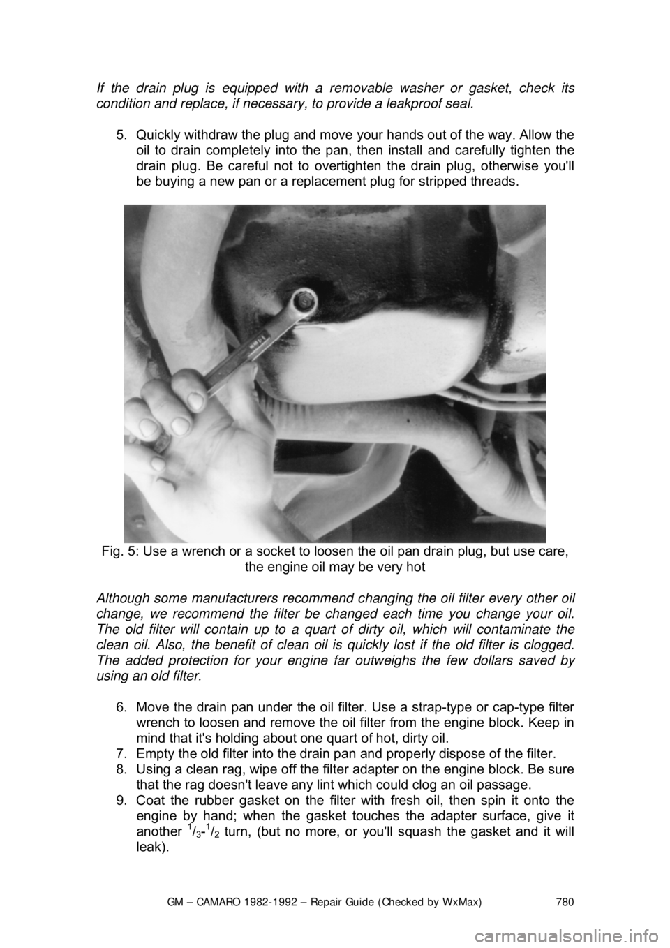
5. Quickly withdraw the plug and move your hands out of the way. Allow the
oil to drain completely into the pan, then install and carefully tighten the
drain plug. Be careful not to overtighten the drain plug, otherwise you'\
ll
be buying a new pan or a replacem ent plug for stripped threads.
Fig. 5: Use a wrench or a socket to l oosen the oil pan drain plug, but use care,
the engine oil may be very hot
Although some manufacturers recommend c hanging the oil filter every other oil
change, we recommend the filter be chan ged each time you change your oil.
The old filter will contain up to a quart of dirty oil, which will contaminate the
clean oil. Also, the benefit of clean oil is quickly lost if the old filter is clogged.
The added protection for your engine far outweighs the few dollars saved by
using an old filter.
6. Move the drain pan under the oil filter. Use a strap-type or cap-type filter
wrench to loosen and remove the oil f ilter from the engine block. Keep in
mind that it's holding about one quart of hot, dirty oil.
7. Empty the old f ilter into the drain pan and proper ly dispose of the filter.
8. Using a clean rag, wipe off the filt er adapter on the engine block. Be sure
that the rag doesn't leave any lint which could clog an oil passage.
9. Coat the rubber gasket on the filter with fresh oil, then spin it onto the
engine by hand; when the gasket touches the adapter surface, give it
another
1/3-1/2 turn, (but no more, or you'll squash the gasket and it will
leak).
Page 785 of 875

GM – CAMARO 1982-1992 – Repair Guide (Checked by WxMax) 785
The automatic transmission fluid and fi
lter should be changed every 15,000
miles (24,000km) if your Camaro is driven in heavy city traffic in hot weather, in
hilly or mountainous terrain, frequent trailer pulling, or uses such as found in
taxi, police car or delivery service. If your Camaro is driven under other than
listed above conditions, change the fl uid and filter every 30,000 miles
(48,300km).
1. Raise and support the car on jackst ands. Place an oil catch pan under
the transmission.
2. Remove the oil pan bolts fr om the front and sides only.
3. Loosen rear oil pan bolts approximately 4 turns.
WARNING - Do not damage the transmission case or oil pan sealing surfaces.
4. Lightly tap the oil pan with a rubber mallet or gently pry it downward to
allow fluid to drain.
5. Remove the remaining oil pan bolt s, then remove the oil pan and pan
gasket.
6. Remove the filter and seal.
7. Clean the transmission case and oi l pan gasket surfaces with suitable
solvent and air dry. Make sure to re move all traces of the old gasket.
To install: 8. Coat the seal with a sm all amount of Transjel®.
9. Install the new s eal onto the filter.
10. Install the new filter into the case.
11. Install the oil pan and new gasket.
On 1991 and later vehicles, inspect t he oil pan screws and washer assemblies.
The screws must not be used if the coni cal washer is reversed. Failure to
replace the screw and washer assembly may result in improper fastening of
system components.
12. Install the oil pan bolts and tighten them to 12 ft. lbs. (16 Nm).
13. Lower the car.
14. Fill the transmission to proper level with Dexron®II fluid.
15. Check cold fluid level reading fo r initial fill. Do not overfill the
transmission.
16. Follow the fluid level che ck procedure described before.
17. Check the oil pan gasket for leaks.
Page 795 of 875
GM – CAMARO 1982-1992 – Repair Guide (Checked by WxMax) 795
Fill the cooling system wit
h a 50/50 mixture of water and Ethylene Glycol
antifreeze. Freezing protection should be appropriate for temperatures of -34°F
(-37°C). When filling the coolant system, add two cooling system sealer pellets
(GM part no. 3634621 or equivalent).
9. Firmly set the parking brake. Run t he engine with the radiator cap OFF,
until normal operating tem perature is reached.
CAUTION - Under some conditions, ethylene glycol is flammable. To avoid
being burned when adding engine coolant, do not spill it on the exhaust system
or on hot engine parts.
10. With the engine idlin g, add engine coolant to t he radiator until the level
reaches the bottom of t he radiator fill neck. Install the cap assembly.
When installing the cap, make sure t hat the arrows on the cap line up
with the overflow tube.
Never add cold water to an overheated engine.
11. Add coolant to the recovery tank, as necessary.
12. After filling the radiator and recovery tank, run the engine until it reaches
normal operating temperature, to ma ke sure that the thermostat has
opened and all the air is bled from the system.
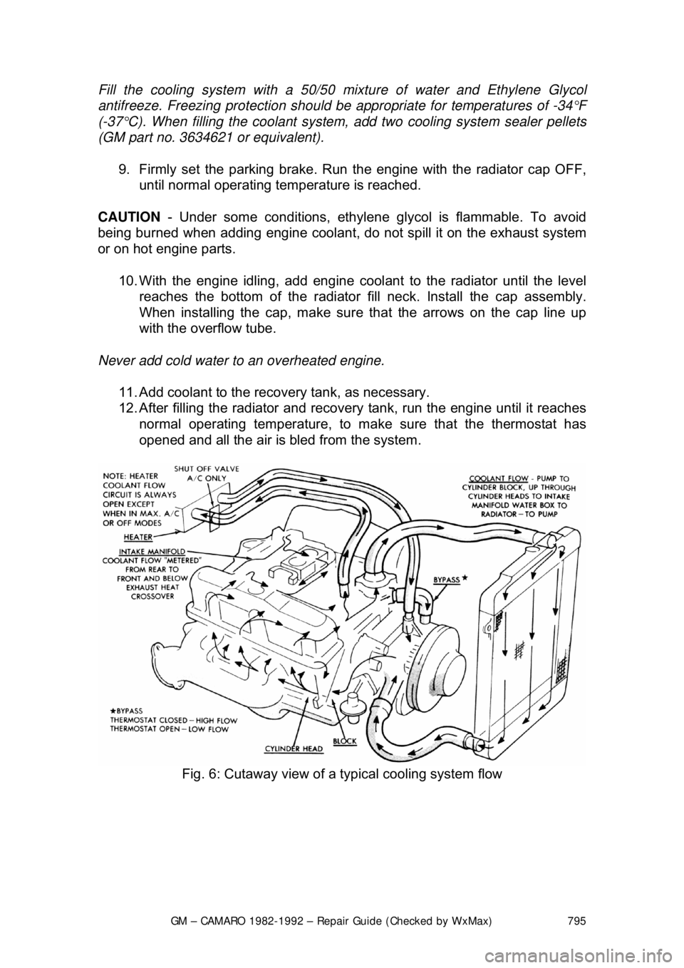
Fig. 6: Cutaway view of a typical cooling system flow
Page 798 of 875
GM – CAMARO 1982-1992 – Repair Guide (Checked by WxMax) 798
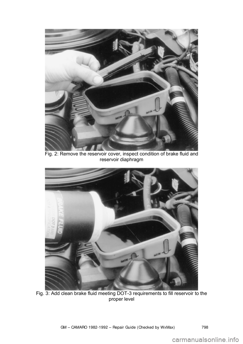
Fig. 2: Remove the reservoir cover, inspect condition of brake fluid and\
reservoir diaphragm
Fig. 3: Add clean brake fluid meeting DOT- 3 requirements to fill reservoir to the
proper level
Page 799 of 875

GM – CAMARO 1982-1992 – Repair Guide (Checked by WxMax) 799
The master cylinder is located in
the left rear section of the engine
compartment. The brake master cylinder consists of an aluminum body and a
translucent nylon reservoir with minimum fill indicators.
1. Check the master cylinder body for cracks. Inspect the area around the
master cylinder for brake fluid. Leaks are indicated if there is at least a
drop of fluid. A damp condition is not normal.
2. Inspect the level of the brake fluid to assure it is at the correct height.
Clean the top of the reservoir cap so t hat all dirt is removed. Remove the
cap(s) or reservoir cover and the reservoir diaphragm.
3. Inspect the brake fluid level. Add clean DOT-3 brake fluid as required to
bring the fluid level to the line located inside the neck of the reservoir fill
opening.
4. Install the reservoir cap.
WARNING - Any sudden decrease in the fluid level indicates a possible leak in
the system and should be check ed out immediately. Do not allow brake fluid to
spill on the vehicle's finish; it will remove the paint. In case of a spill, flush the
area with water and mild soap.
HYDRAULIC CLUTCH SYSTEM
FLUID RECOMMENDATIONS
• 1982-1991 - Delco Supreme II Brake fl uid or an equivalent fluid that
meets DOT-3 specifications
• 1992 - Hydraulic clutch fluid, GM part number 12345347 or equivalent
LEVEL CHECK
The clutch master cylinder is normally lo cated below the brake master cylinder.
The reservoir for it is located right bes ide the brake master cylinder and is made
of translucent nylon. The fl uid level of the reservoir sh ould be kept near the top
of the observation window. Before removing the cap to the reservoir, clean all
dirt from the area. This will prevent syst em contamination due to particles falling
into the reservoir when the caps are removed.
POWER STEERING PUMP
FLUID RECOMMENDATIONS
• GM power steering fluid, or equivalent.
Page 803 of 875
GM – CAMARO 1982-1992 – Repair Guide (Checked by WxMax) 803
5. Pry out the inner seal and
remove the inner bearing.
6. Wipe out the grease from inside the hub.
7. Clean the wheel bearings thor oughly with solvent and check their
condition before installation. Afte r cleaning, check parts for excessive
wear and replace damaged parts.
WARNING - Do not allow the bearing to spin when blowing dry with
compressed air, as this would allow t he bearing to turn without lubrication.
8. Apply a sizable amount of lubricant to the palm of one hand. Using your
other hand, work the bearing into the lubricant so that the grease is
pushed through the rollers and out t he other side. Keep rotating the
bearing while continuing to push the lubricant through it.
9. Apply grease to the inside of t he hub and install the inner bearing in the
hub. Install a new grease seal, be careful not to damage the seal.
10. Install the disc/hub assembly onto t he steering knuckle. Install the outer
bearing, thrust washer and castle nu t. Torque the nut to 12 ft. lbs. (16
Nm) while turning the wheel.
11. Back the nut off and retighten it by hand until nearest slot aligns with the
cotter pin hole.
12. Insert a new cotter pin.
13. Mount a dial indicator onto the vehi cle so that any end-play in the hub
can be measured. Measure the end-play and record the value. End-play
should be between 0.001-0.005 in. (0.025- 0.127mm). If play exceeds this
tolerance, the wheel bearings should be replaced.
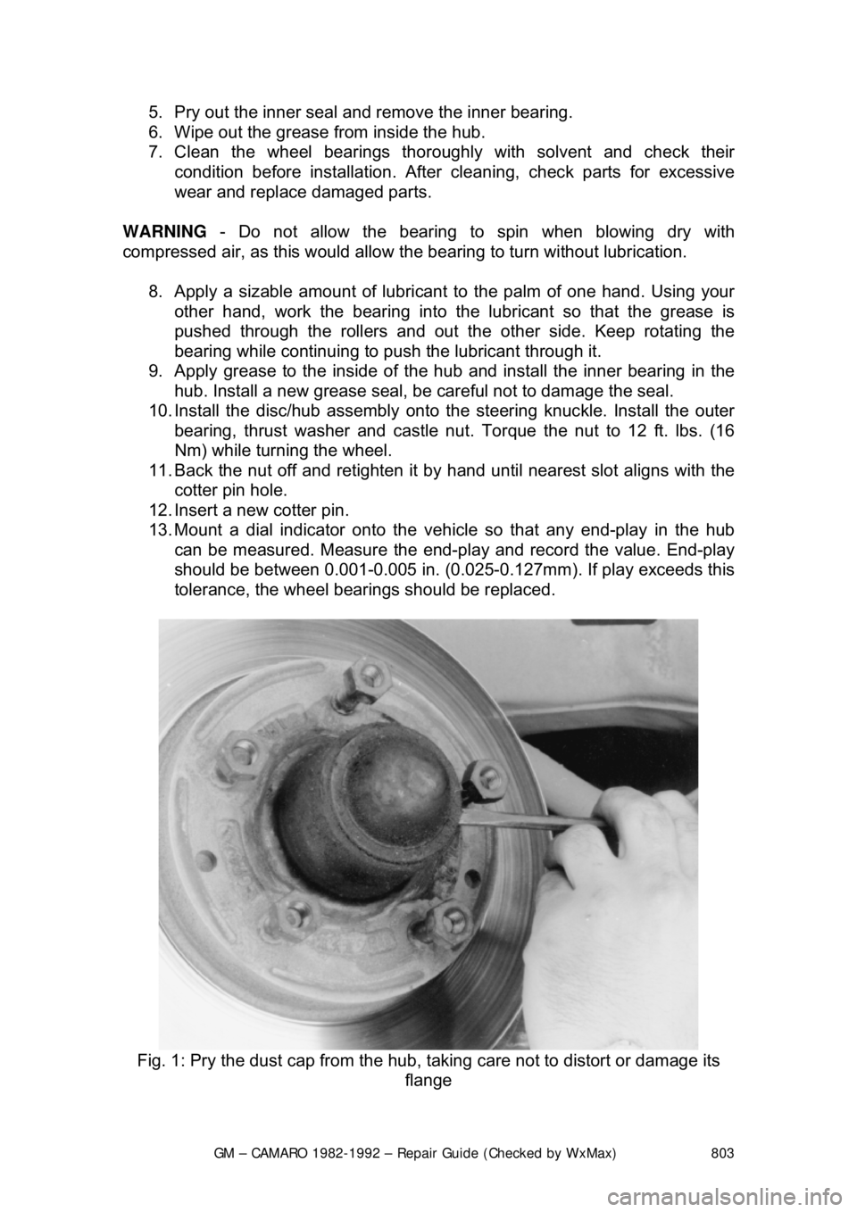
Fig. 1: Pry the dust cap fr om the hub, taking care not to distort or damage its
flange
Page 829 of 875
GM – CAMARO 1982-1992 – Repair Guide (Checked by WxMax) 829
12. Fully tighten the lower bolts onl
y when the front suspension is on the
ground. Torque the steering knuckle-to-strut nuts to 125 ft. lbs. (170 Nm)
followed by a 120 degree turn. Do not exceed a final torque of 148 Ft.
lbs. (200 Nm).
13. Install the brake caliper
14. Install the wheel and tire assembly.
15. Lower the front of the vehicle.
16. From inside the engine compartm ent, tighten the upper strut to upper
mount nut to 44 ft. lbs. (60 Nm).
17. Have the front end aligned.
OVERHAUL
The OEM domestic struts are serviced by replacement of the entire unit. There
is no strut cartridge to replace.
LOWER BALL JOINT
INSPECTION
Before performing this inspection, make sure the wheel bearings are adjusted
correctly and that the control arm bushings are in good condition.
1. Jack the car up under the front lower control arm at the spring seat.
2. Raise the car until t here is 1-2 in. (25-51mm) of clearance under the
wheel.
3. Insert a bar under the wheel and pr y upward. If the wheel raises more
than
1/8 in. (3mm), the ball joints are worn. Determine if the lower ball
joint is worn by visual inspec tion while prying on the wheel.
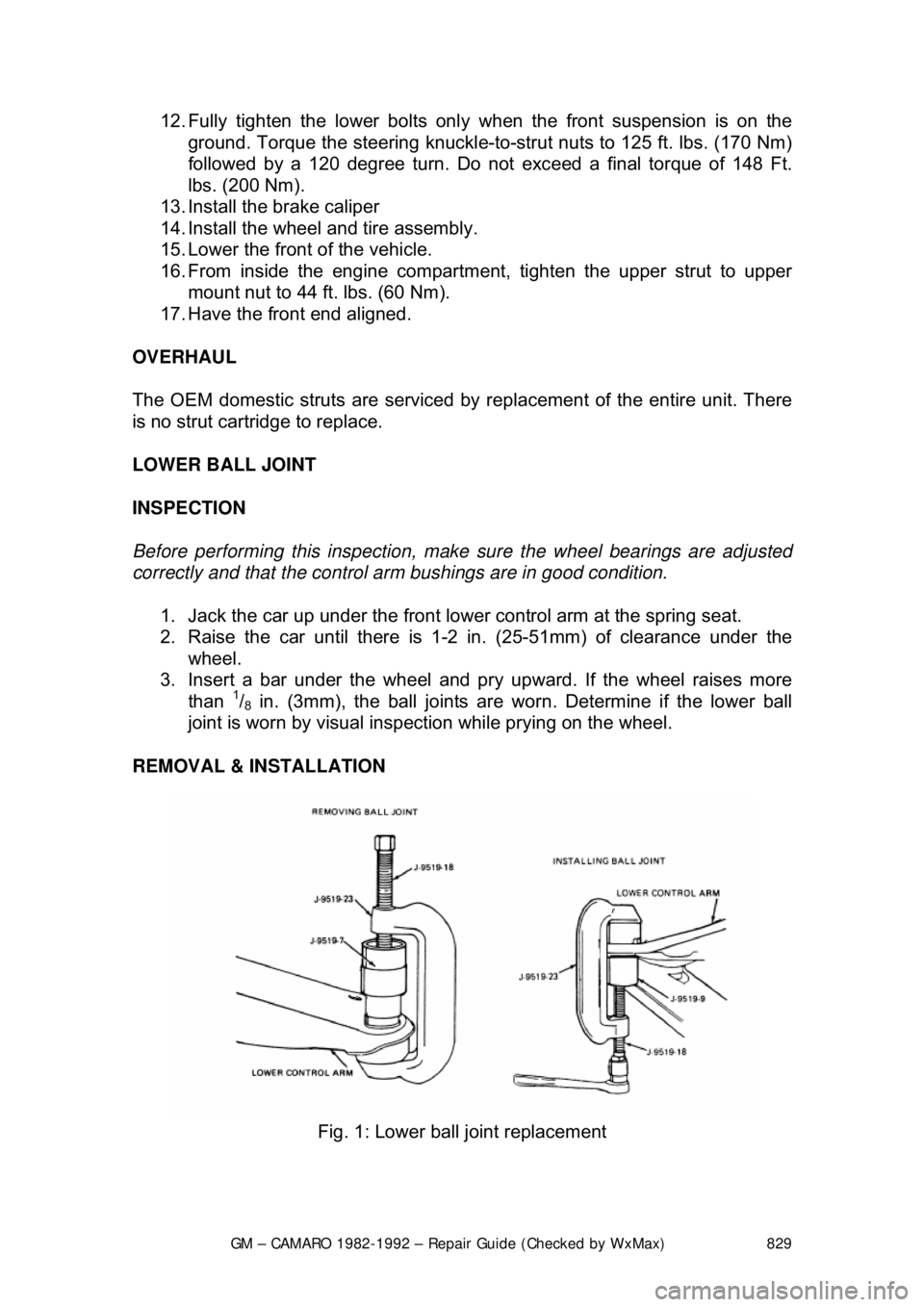
REMOVAL & INSTALLATION
Fig. 1: Lower ball joint replacement
Page 834 of 875

GM – CAMARO 1982-1992 – Repair Guide (Checked by WxMax) 834
1. Raise the car and support it at the lower arm.
2. Remove the hub dust cover and spindle cotter pin. Loosen the nut.
3. While spinning the wheel
, snug the nut down to seat the bearings. Do not
exert over 12 ft. lbs. (16 Nm) of force on the nut.
4. Back the nut off
1/4 turn or until it is just loos e. Line up the cotter pin hole
in the spindle with the hole in the nut.
5. Insert a new cotter pin. E ndplay should be between 0.001-0.005 in.
(0.03-0.13mm). If play exceeds this to lerance, the wheel bearings should
be replaced.
REMOVAL & INSTALLATION 1. Raise the car and support it at t he lower arm. Remove the wheel.
Remove the brake caliper and support it on a wire.
2. Remove the dust cap, cotter pin, ca stle nut, thrust washer and outside
wheel bearing. Pull the disc/hub assemb ly from the steering knuckle.
3. Pry out the inner seal and remove the inner bearing. If necessary to
remove the inner bearing races, use a hammer and a brass drift to drive
the bearing races from the hub.
4. Clean all parts in kerosene or e quivalent, DO NOT use gasoline. After
cleaning, check parts for excessive wear and replace damaged parts.
5. Smear grease inside of hub. Install the bearing races into hub, using a
hammer and a brass drift. Drive the ra ces in until they seat against the
shoulder of the hub.
6. Pack the bearings with grease and install the inner bearing in the hub.
Install a new grease seal, be careful not to damage the seal.
7. Install the disc/hub assembly onto t he steering knuckle. Install the outer
bearing, thrust washer and castle nut. Tighten the nut until the wheel
does not turn freely.
8. Back off the nut until the wheel tu rns freely and install the cotter pin.
Install the dust cap, caliper and wheel. Lower the car.
PACKING
Clean the wheel bearings thoroughly with solvent and check their condition
before installation.
CAUTION - Do not blow the beari ng dry with compressed ai r as this could allow
the bearing to turn without lubrication.
Apply a sizable amount of lubricant to the palm of one hand. Using your other
hand, work the bearing into the lubricant so that the grease is pushed through
the rollers and out the other side. Keep ro tating the bearing while continuing to
push the lubricant through it.