Page 853 of 875

GM – CAMARO 1982-1992 – Repair Guide (Checked by WxMax) 853
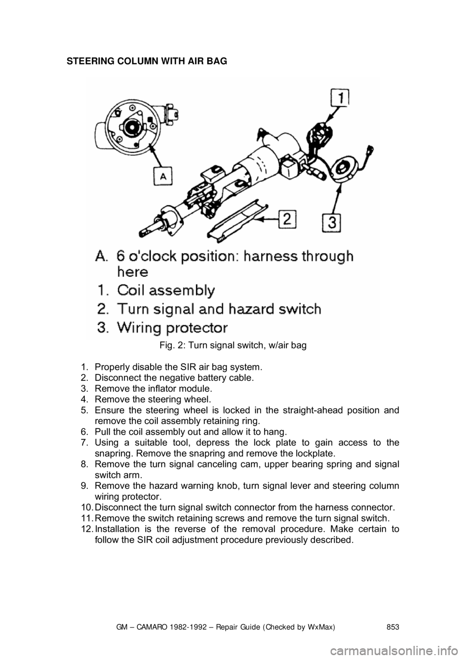
STEERING COLUMN WITH AIR BAG
Fig. 2: Turn signal switch, w/air bag
1. Properly disable the SIR air bag system.
2. Disconnect the negative battery cable.
3. Remove the inflator module.
4. Remove the steering wheel.
5. Ensure the steering wheel is locked in the straight-ahead position and
remove the coil assembly retaining ring.
6. Pull the coil assembly out and allow it to hang.
7. Using a suitable tool, depress the lock plate to gain access to the
snapring. Remove the snapring and remove the lockplate.
8. Remove the turn signal cancelin g cam, upper bearing spring and signal
switch arm.
9. Remove the hazard warning knob, tu rn signal lever and steering column
wiring protector.
10. Disconnect the turn signal switch connector from the harness connector.
11. Remove the switch retaining screws and remove the turn signal switch.
12. Installation is the reverse of t he removal procedure. Make certain to
follow the SIR coil adjustment pr ocedure previously described.
Page 854 of 875

GM – CAMARO 1982-1992 – Repair Guide (Checked by WxMax) 854
IGNITION SWITCH
WARNING
- Before attempting any repairs involving the steering wheel or
disassembly of it, ensure that the Supple mental Inflatable Restraint (Air Bag)
system is properly disarmed.
REPLACEMENT
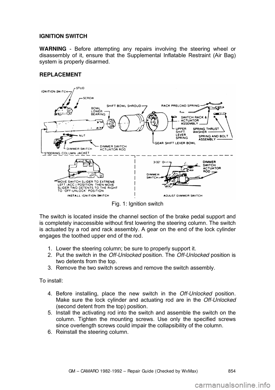
Fig. 1: Ignition switch
The switch is located inside the channe l section of the brake pedal support and
is completely inaccessible without firs t lowering the steering column. The switch
is actuated by a rod and rack assembly . A gear on the end of the lock cylinder
engages the toothed upper end of the rod.
1. Lower the steering column; be sure to properly support it.
2. Put the switch in the Off-Unlocked position. The Off-Unlocked position is
two detents from the top.
3. Remove the two switch screws and remove the switch assembly.
To install: 4. Before installing, place the new switch in the Off-Unlocked position.
Make sure the lock cylinder and actuating rod are in the Off-Unlocked
(second detent from th e top) position.
5. Install the activating rod into the switch and assemble the switch on the
column. Tighten the mount ing screws. Use only the specified screws
since overlength screws could impair the collapsibility of the column.
6. Reinstall the steering column.
Page 855 of 875
GM – CAMARO 1982-1992 – Repair Guide (Checked by WxMax) 855
IGNITION LOCK CYLINDER
WARNING
- Before attempting any repairs involving the steering wheel or
disassembly of it, ensure that the Supple mental Inflatable Restraint (Air Bag)
system is properly disarmed.
REMOVAL & INSTALLATION
Fig. 1: Lock cylinder replacement
Fig. 2: Lock cylinder w/VATS
Page 856 of 875

GM – CAMARO 1982-1992 – Repair Guide (Checked by WxMax) 856
1. Properly disable the SIR
air bag system, if equipped.
2. Place the lock in the Run position.
3. Remove the lock plate, turn signal switch and buzzer switch.
4. Remove the screw and lock cylinder.
CAUTION - If the screw is dropped on removal, it could fall into the column,
requiring complete disassembly to retrieve the screw.
To install:
5. Rotate the cylinder clockwise to a lign cylinder key with the keyway in the
housing.
6. Push the lock all the way in.
7. Install the screw. Tighten the screw to 14 inch lbs. (1.5 Nm) for
adjustable columns and 25 inch lbs. (2.8 Nm) for standard columns. Re-
center the SIR coil assembly as previously directed.
STEERING COLUMN
WARNING - Before attempting any repairs involving the steering wheel or
disassembly of it, ensure that the Supple mental Inflatable Restraint (Air Bag)
system is properly disarmed.
REMOVAL & INSTALLATION
The front of the dash mount ing plates must be loosened whenever the steering
column is to be lowered from the instrument panel.
1. Disconnect the negative battery cable.
2. On 1990-92 vehicles, disable the S upplemental Inflatable Restraint (SIR)
system as follows: a. Turn the steering wheel so th e vehicle's wheels are pointing
straight-ahead.
The wheels of the vehicle must be in the straight-ahead position
and the steering column in the locked position before proceeding
with steering column remo val. Failure to follow this procedure will
cause the SIR coil to become uncentered, resulting in damage to
the coil assembly.
b. Remove the SIR fuse from the fuse block.
c. Remove the left sound insulator by removing the nut from the stud
and gently prying the insulator from the knee bolster.
d. Disconnect the Connector Position Assurance (CPA) and yellow 2-way SIR harness connector at the base of the steering column.
3. Remove the nut and bolt from t he upper intermediate shaft coupling.
Separate the coupling from the lo wer end of the steering column.
4. Remove the steering w heel, if the column is to be replaced or repaired
on the bench.
5. Remove the knee bolster and bracket, if equipped.