1982 CHEVROLET CAMARO warning
[x] Cancel search: warningPage 799 of 875

GM – CAMARO 1982-1992 – Repair Guide (Checked by WxMax) 799
The master cylinder is located in
the left rear section of the engine
compartment. The brake master cylinder consists of an aluminum body and a
translucent nylon reservoir with minimum fill indicators.
1. Check the master cylinder body for cracks. Inspect the area around the
master cylinder for brake fluid. Leaks are indicated if there is at least a
drop of fluid. A damp condition is not normal.
2. Inspect the level of the brake fluid to assure it is at the correct height.
Clean the top of the reservoir cap so t hat all dirt is removed. Remove the
cap(s) or reservoir cover and the reservoir diaphragm.
3. Inspect the brake fluid level. Add clean DOT-3 brake fluid as required to
bring the fluid level to the line located inside the neck of the reservoir fill
opening.
4. Install the reservoir cap.
WARNING - Any sudden decrease in the fluid level indicates a possible leak in
the system and should be check ed out immediately. Do not allow brake fluid to
spill on the vehicle's finish; it will remove the paint. In case of a spill, flush the
area with water and mild soap.
HYDRAULIC CLUTCH SYSTEM
FLUID RECOMMENDATIONS
• 1982-1991 - Delco Supreme II Brake fl uid or an equivalent fluid that
meets DOT-3 specifications
• 1992 - Hydraulic clutch fluid, GM part number 12345347 or equivalent
LEVEL CHECK
The clutch master cylinder is normally lo cated below the brake master cylinder.
The reservoir for it is located right bes ide the brake master cylinder and is made
of translucent nylon. The fl uid level of the reservoir sh ould be kept near the top
of the observation window. Before removing the cap to the reservoir, clean all
dirt from the area. This will prevent syst em contamination due to particles falling
into the reservoir when the caps are removed.
POWER STEERING PUMP
FLUID RECOMMENDATIONS
• GM power steering fluid, or equivalent.
Page 802 of 875

GM – CAMARO 1982-1992 – Repair Guide (Checked by WxMax) 802
BODY LUBRICATION
HOOD LATCH AND HINGES
Clean the latch surfaces and
apply clean engine oil to the latch pilot bolts and
the spring anchor. Use the engine oil to l ubricate the hood hinges as well. Use a
chassis grease to lubricate all the pivot points in the latch release mechanism.
DOOR HINGES
The gas tank filler door, car door, and rear hatch or trunk lid hinges should be
wiped clean and lubricated with clean engi ne oil. Silicone spray also works well
on seals, but must be applied more often. Use engine oil to lubricate the trunk
or hatch lock mechanism and the lock bo lt and striker. The door lock cylinders
can be lubricated easily with a shot of silicone spray or one of the many dry
penetrating lubricants commercially available.
PARKING BRAKE LINKAGE
Use chassis grease on the parking brake c able where it contacts the guides,
links, levers, and pulleys. The grease s hould be water resistant for durability.
ACCELERATOR LINKAGE
Lubricate the throttle lever, and the accele rator pedal lever at the support inside
the car with clean engine oil.
TRANSMISSION SHIFT LINKAGE
Lubricate the shift linkage with water re sistant chassis grease which meets GM
Specification 6031M or its equal.
FRONT WHEEL BEARINGS
Once every 30,000 miles, clean and repack wheel bearings with a wheel
bearing packer. Remove any excess grea se from the exposed surface of the
hub and seal.
REMOVAL, REPACKING, INSTA LLATION AND ADJUSTMENT
WARNING - It is important that wheel b earings be properly adjusted after
installation. Improperly adj usted wheel bearings can c ause steering instability,
front end shimmy and wander, and increased tire wear.
1. Raise the car and support it at the lower arm. Remove the tire and wheel
assembly.
2. Remove the brake caliper and support it on a wire.
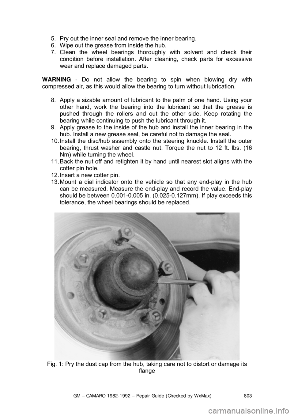
3. Remove the dust cap, cotter pin, ca stle nut, thrust washer and outside
wheel bearing.
4. Pull the disc/hub assembly from the steering knuckle.
Page 803 of 875

GM – CAMARO 1982-1992 – Repair Guide (Checked by WxMax) 803
5. Pry out the inner seal and
remove the inner bearing.
6. Wipe out the grease from inside the hub.
7. Clean the wheel bearings thor oughly with solvent and check their
condition before installation. Afte r cleaning, check parts for excessive
wear and replace damaged parts.
WARNING - Do not allow the bearing to spin when blowing dry with
compressed air, as this would allow t he bearing to turn without lubrication.
8. Apply a sizable amount of lubricant to the palm of one hand. Using your
other hand, work the bearing into the lubricant so that the grease is
pushed through the rollers and out t he other side. Keep rotating the
bearing while continuing to push the lubricant through it.
9. Apply grease to the inside of t he hub and install the inner bearing in the
hub. Install a new grease seal, be careful not to damage the seal.
10. Install the disc/hub assembly onto t he steering knuckle. Install the outer
bearing, thrust washer and castle nu t. Torque the nut to 12 ft. lbs. (16
Nm) while turning the wheel.
11. Back the nut off and retighten it by hand until nearest slot aligns with the
cotter pin hole.
12. Insert a new cotter pin.
13. Mount a dial indicator onto the vehi cle so that any end-play in the hub
can be measured. Measure the end-play and record the value. End-play
should be between 0.001-0.005 in. (0.025- 0.127mm). If play exceeds this
tolerance, the wheel bearings should be replaced.
Fig. 1: Pry the dust cap fr om the hub, taking care not to distort or damage its
flange
Page 818 of 875

GM – CAMARO 1982-1992 – Repair Guide (Checked by WxMax) 818
•
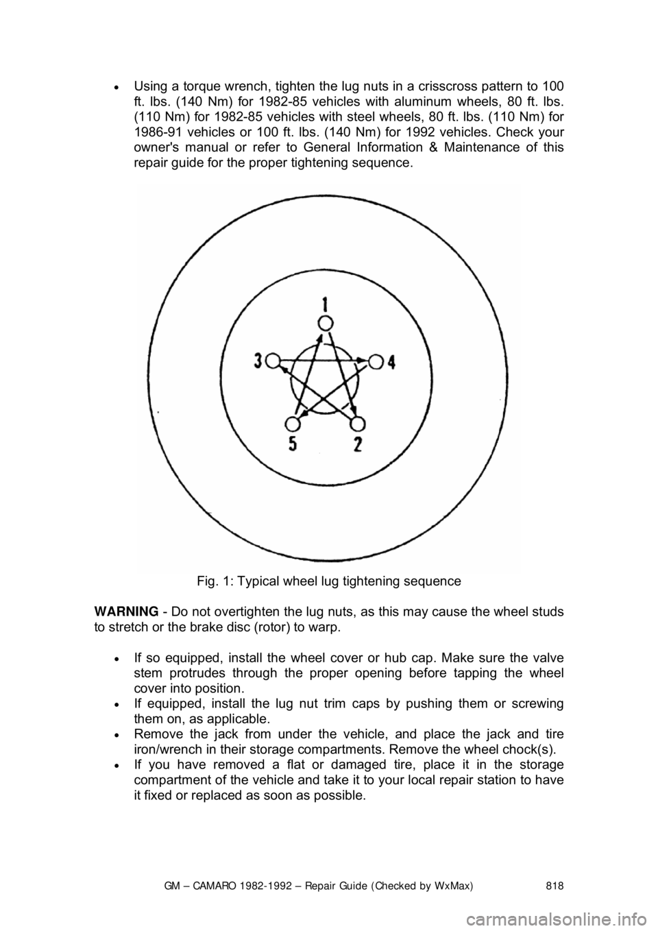
Using a torque wrench, tighten the lug nuts in a crisscross pattern to 100
ft. lbs. (140 Nm) for 1982-85 vehicles with aluminum wheels, 80 ft. lbs.
(110 Nm) for 1982-85 vehicles with st eel wheels, 80 ft. lbs. (110 Nm) for
1986-91 vehicles or 100 ft. lbs. (140 Nm) for 1992 vehicles. Check your
owner's manual or refer to General Information & Maintenance of this
repair guide for the proper tightening sequence.
Fig. 1: Typical wheel lug tightening sequence
WARNING - Do not overtighten the lug nuts, as this may cause the wheel studs
to stretch or the brake disc (rotor) to warp.
• If so equipped, install the wheel cover or hub cap. Make sure the valve
stem protrudes throu gh the proper opening bef ore tapping the wheel
cover into position.
• If equipped, install the lug nut trim caps by pushing them or screwing
them on, as applicable.
• Remove the jack from under the v ehicle, and place the jack and tire
iron/wrench in their storage compartment s. Remove the wheel chock(s).
• If you have removed a flat or damaged tire, place it in the storage
compartment of the vehicle and take it to your local repair station to have
it fixed or replaced as soon as possible.
Page 845 of 875

GM – CAMARO 1982-1992 – Repair Guide (Checked by WxMax) 845
STABILIZER (SWAY) BAR
REMOVAL & INSTALLATION
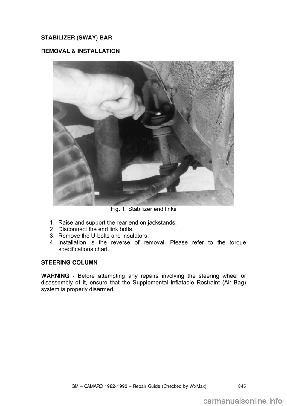
Fig. 1: Stabilizer end links
1. Raise and support the rear end on jackstands.
2. Disconnect the end link bolts.
3. Remove the U-bolts and insulators.
4. Installation is the reverse of re moval. Please refer to the torque
specifications chart.
STEERING COLUMN
WARNING - Before attempting any repairs involving the steering wheel or
disassembly of it, ensure that the Supple mental Inflatable Restraint (Air Bag)
system is properly disarmed.
Page 846 of 875

GM – CAMARO 1982-1992 – Repair Guide (Checked by WxMax) 846
AIR BAG
WARNING
- Before attempting any repairs involving the steering wheel or
disassembly of it, ensure that the Supple mental Inflatable Restraint (Air Bag)
system is properly disarmed.
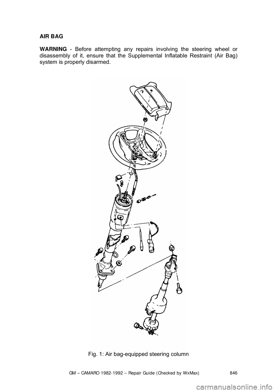
Fig. 1: Air bag-equipped steering column
Page 847 of 875

GM – CAMARO 1982-1992 – Repair Guide (Checked by WxMax) 847
DISARMING
1. Turn the steering wheel to align the w heels in the straight-ahead position.
2. Turn the ignition switch to the LOCK position.
3. Remove the SIR air bag fuse from the fuse block.
4. Remove the left side trim panel and disconnect the yellow 2-way SIR
harness wire connector at the bas e of the steering column.
To enable system: 5. Turn the ignition switch to the LOCK position.
6. Reconnect the yello w 2-way connector at the base of the steering
column.
7. Reinstall the SIR fuse and the left side trim panel.
8. Turn the ignition switch to the RUN position.
9. Verify the SIR indicator light flashes 7-9 times, if not as specified, inspect
system for malfunction or c ontact the manufacturer.
For more details on the SIR system - including disarming instructions for
passenger bags - please refer to Chassis Electrical in this repair guide.
SUPPLEMENTAL INFLATABLE REST RAINT (SIR) COIL ASSEMBLY
After performing repairs on the inter nals of the steering column the coil
assembly must be centered in order to avoid damaging the coil or accidental
deployment of the air bag. There are 2 different styles of coils, one rotates
clockwise and the other rotates counterclockwise.
ADJUSTMENT (CENTERING THE COIL) 1. With the system properly disarmed, hold the coil assembly with the clear
bottom up to see the coil ribbon.
2. While holding the coil assembly, depr ess the lock spring and rotate the
hub in the direction of the arrow until it stops. The coil should now be
wound up snug against the center hub.
3. Rotate the coil assembly in the opposite direction approximately 2
1/2
turns and release the lock spring between the locking tabs in front of the
arrow.
4. Install the coil assembly onto the steering shaft.
STEERING WHEEL
WARNING - Before attempting any repairs involving the steering wheel or
disassembly of it, ensure that the Supple mental Inflatable Restraint (Air Bag)
system is properly disarmed.
REMOVAL & INSTALLATION
If the vehicle is equipped with a SIR (A ir Bag) system, ensure that the proper
disarming procedure is followed.
Page 850 of 875

GM – CAMARO 1982-1992 – Repair Guide (Checked by WxMax) 850
TURN SIGNAL SWITCH
WARNING - Before attempting any repai
rs involving the steering wheel or
disassembly of it, ensure that the Supple mental Inflatable Restraint (Air Bag)
system is properly disarmed.
REMOVAL & INSTALLATION
STANDARD COLUMNS WITHOUT AIR BAG 1. Remove the steering wheel as pr eviously outlined. Remove the trim
cover.
2. Pry the cover off, and lift the cover off the shaft.
3. Position the U-shaped lockplate co mpressing tool on the end of the
steering shaft and compress the lock plate by turning the shaft nut
clockwise. Pry the wire snapri ng out of the shaft groove.
4. Remove the tool and lift t he lockplate off the shaft.
5. Remove the canceling cam assembly and upper bearing preload spring from the shaft.
6. Remove the turn signal lever. Pu sh the flasher knob in and unscrew it.
On models equipped with a button and a knob, remove the button
retaining screw, then remove the button, spring, and knob.
7. Pull the switch connect or out the mast jacket and tape the upper part to
facilitate switch removal. Attach a l ong piece of wire to the turn signal
switch connector. When in stalling the turn signal switch, feed this wire
through the column first, and then use this wire to pull the switch
connector into position. On tilt wheel s, place the turn signal and shifter
housing in low position and remove the harness cover.
8. Remove the three switch mounting screws. Remove the switch by pulling
it straight up while guiding the wir ing harness cover through the column.
To install: 9. Install the replacement switch by working the connector and cover down
through the housing and under the bracket. On tilt models, the connector
is worked down through the housing, under the bracket, and then the
cover is installed on the harness.
10. Install the switch mounting screw s and the connector on the mast jacket
bracket. Install the column -to-dash trim plate.
11. Install the flasher knob and the turn signal lever.
12. With the turn signal lever in neutral and the fl asher knob out, slide the
upper bearing preload spring, and canc eling cam assembly onto the
shaft.
13. Position the lock plate on the s haft and press it down until a new
snapring can be inserted in the shaft groove. Always use a new snapring
when assembling.
14. Install the cover and the steering wheel.