Page 798 of 875
GM – CAMARO 1982-1992 – Repair Guide (Checked by WxMax) 798
Fig. 2: Remove the reservoir cover, inspect condition of brake fluid and\
reservoir diaphragm
Fig. 3: Add clean brake fluid meeting DOT- 3 requirements to fill reservoir to the
proper level
Page 799 of 875

GM – CAMARO 1982-1992 – Repair Guide (Checked by WxMax) 799
The master cylinder is located in
the left rear section of the engine
compartment. The brake master cylinder consists of an aluminum body and a
translucent nylon reservoir with minimum fill indicators.
1. Check the master cylinder body for cracks. Inspect the area around the
master cylinder for brake fluid. Leaks are indicated if there is at least a
drop of fluid. A damp condition is not normal.
2. Inspect the level of the brake fluid to assure it is at the correct height.
Clean the top of the reservoir cap so t hat all dirt is removed. Remove the
cap(s) or reservoir cover and the reservoir diaphragm.
3. Inspect the brake fluid level. Add clean DOT-3 brake fluid as required to
bring the fluid level to the line located inside the neck of the reservoir fill
opening.
4. Install the reservoir cap.
WARNING - Any sudden decrease in the fluid level indicates a possible leak in
the system and should be check ed out immediately. Do not allow brake fluid to
spill on the vehicle's finish; it will remove the paint. In case of a spill, flush the
area with water and mild soap.
HYDRAULIC CLUTCH SYSTEM
FLUID RECOMMENDATIONS
• 1982-1991 - Delco Supreme II Brake fl uid or an equivalent fluid that
meets DOT-3 specifications
• 1992 - Hydraulic clutch fluid, GM part number 12345347 or equivalent
LEVEL CHECK
The clutch master cylinder is normally lo cated below the brake master cylinder.
The reservoir for it is located right bes ide the brake master cylinder and is made
of translucent nylon. The fl uid level of the reservoir sh ould be kept near the top
of the observation window. Before removing the cap to the reservoir, clean all
dirt from the area. This will prevent syst em contamination due to particles falling
into the reservoir when the caps are removed.
POWER STEERING PUMP
FLUID RECOMMENDATIONS
• GM power steering fluid, or equivalent.
Page 828 of 875

GM – CAMARO 1982-1992 – Repair Guide (Checked by WxMax) 828
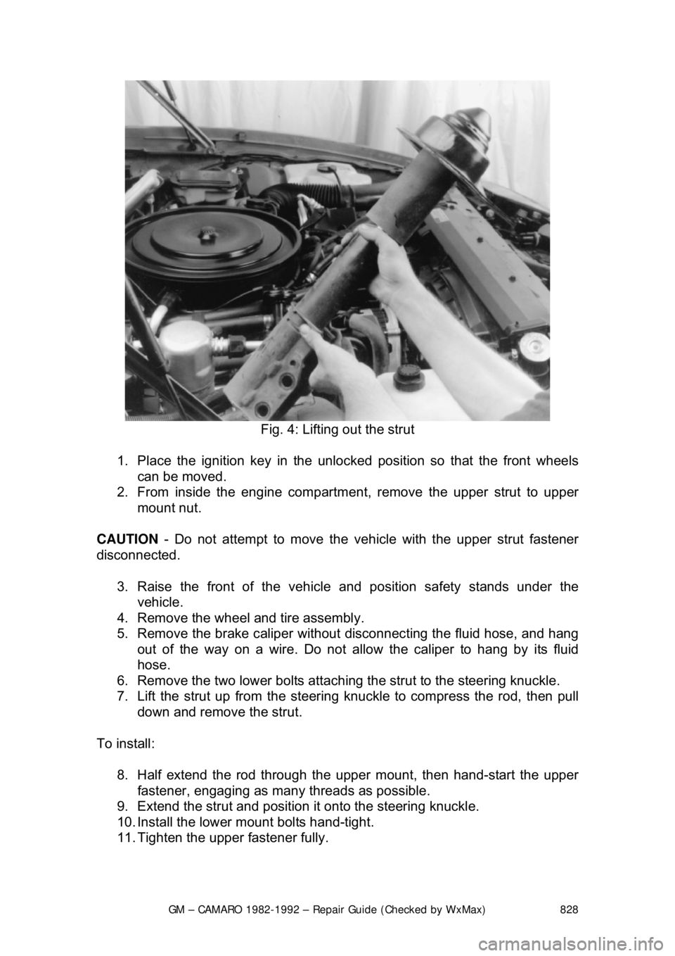
Fig. 4: Lifting out the strut
1. Place the ignition key in the unlock ed position so that the front wheels
can be moved.
2. From inside the engine compartm ent, remove the upper strut to upper
mount nut.
CAUTION - Do not attempt to move the ve hicle with the upper strut fastener
disconnected.
3. Raise the front of the vehicl e and position safety stands under the
vehicle.
4. Remove the wheel and tire assembly.
5. Remove the brake caliper without disconnecting the fluid hose, and hang
out of the way on a wire. Do not allo w the caliper to hang by its fluid
hose.
6. Remove the two lower bolts attachi ng the strut to the steering knuckle.
7. Lift the strut up from the steering k nuckle to compress the rod, then pull
down and remove the strut.
To install: 8. Half extend the rod through th e upper mount, then hand-start the upper
fastener, engaging as many threads as possible.
9. Extend the strut and position it onto the steering knuckle.
10. Install the lower mount bolts hand-tight.
11. Tighten the upper fastener fully.
Page 833 of 875

GM – CAMARO 1982-1992 – Repair Guide (Checked by WxMax) 833
1. Siphon some brake fluid from the ma
ster cylinder. Raise and support the
vehicle.
2. Remove the wheel and tire. Remo ve the brake hose from the strut.
3. Remove the caliper and support on a wire. Refer to Brakes for
procedures, then remove the hub-and-disc.
4. Remove the splash shield. Disc onnect the tie rod from the steering
knuckle.
5. Support the lower control arm and disconnect the ball joint from the
steering knuckle using tool J-24292A.
6. Remove the 2 bolts securing the stru t to the steering knuckle and remove
the steering knuckle.
To install: 7. Place the steering knu ckle into position and install the 2 bolts securing
the strut to the st eering knuckle.
8. Support the lower control arm and c onnect the ball joint to the steering
knuckle.
9. Connect the tie rod to the steering knuckle. Install the splash shield.
10. Install the caliper.
11. Install the brake hose from the strut. Install the wheel and tire.
12. Lower the vehicle and refill the master cylinder with brake fluid.
FRONT WHEEL BEARINGS
ADJUSTMENT
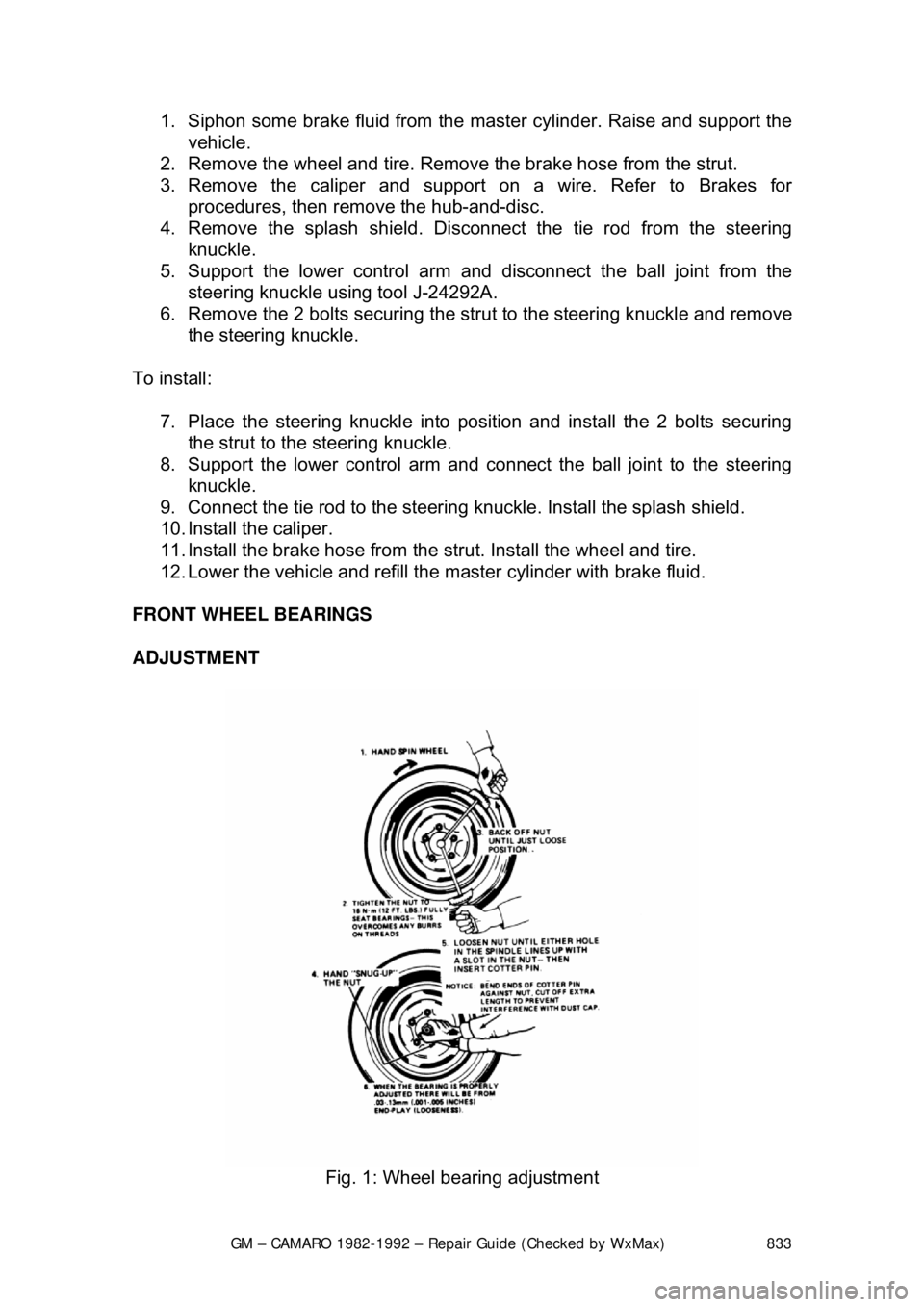
Fig. 1: Wheel bearing adjustment