Page 821 of 875
GM – CAMARO 1982-1992 – Repair Guide (Checked by WxMax) 821
If a press is not availabl
e, start the lug stud through the bore in the hub, then
position about 4 flat washers over t he stud and thread the lug nut. Hold the
hub/rotor while tightening the lug nut, and the stud should be drawn into
position. MAKE SURE THE STUD IS FU LLY SEATED, then remove the lug nut
and washers.
7. Install the rotor and adjust the wheel bearings.
8. Install the brake caliper and pads.
9. Install the wheel, then remove the jackstands and carefully lower the
vehicle.
10. Tighten the lug nuts to the proper torque.
WITH DRUM BRAKES 1. Raise the vehicle and safely su pport it with jackstands, then remove the
wheel.
2. Remove the brake drum.
3. If necessary to provide clearance, re move the brake shoes, as outlined in
Brakes of this repair guide.
Fig. 4: Exploded view of t he drum, axle flange and stud
Page 822 of 875
GM – CAMARO 1982-1992 – Repair Guide (Checked by WxMax) 822
Fig. 5: Use a C-clamp and socket to press out the stud
Fig. 6: Force the stud onto the axle flange using washers and a lug nut
4. Using a large C-clamp and socket, pre ss the stud from the axle flange.
5. Coat the serrated part of the stud with liquid soap and place it into the
hole.
To install: 6. Position about 4 flat washers over the stud and thread the lug nut. Hold
the flange while tightening the lug nut, and the stud should be drawn into
position. MAKE SURE THE STUD IS FULLY SEATED, then remove the
lug nut and washers.
7. If applicable, install the brake shoes.
8. Install the brake drum.
9. Install the wheel, then remove the jackstands and carefully lower the
vehicle.
10. Tighten the lug nuts to the proper torque.
Page 829 of 875

GM – CAMARO 1982-1992 – Repair Guide (Checked by WxMax) 829
12. Fully tighten the lower bolts onl
y when the front suspension is on the
ground. Torque the steering knuckle-to-strut nuts to 125 ft. lbs. (170 Nm)
followed by a 120 degree turn. Do not exceed a final torque of 148 Ft.
lbs. (200 Nm).
13. Install the brake caliper
14. Install the wheel and tire assembly.
15. Lower the front of the vehicle.
16. From inside the engine compartm ent, tighten the upper strut to upper
mount nut to 44 ft. lbs. (60 Nm).
17. Have the front end aligned.
OVERHAUL
The OEM domestic struts are serviced by replacement of the entire unit. There
is no strut cartridge to replace.
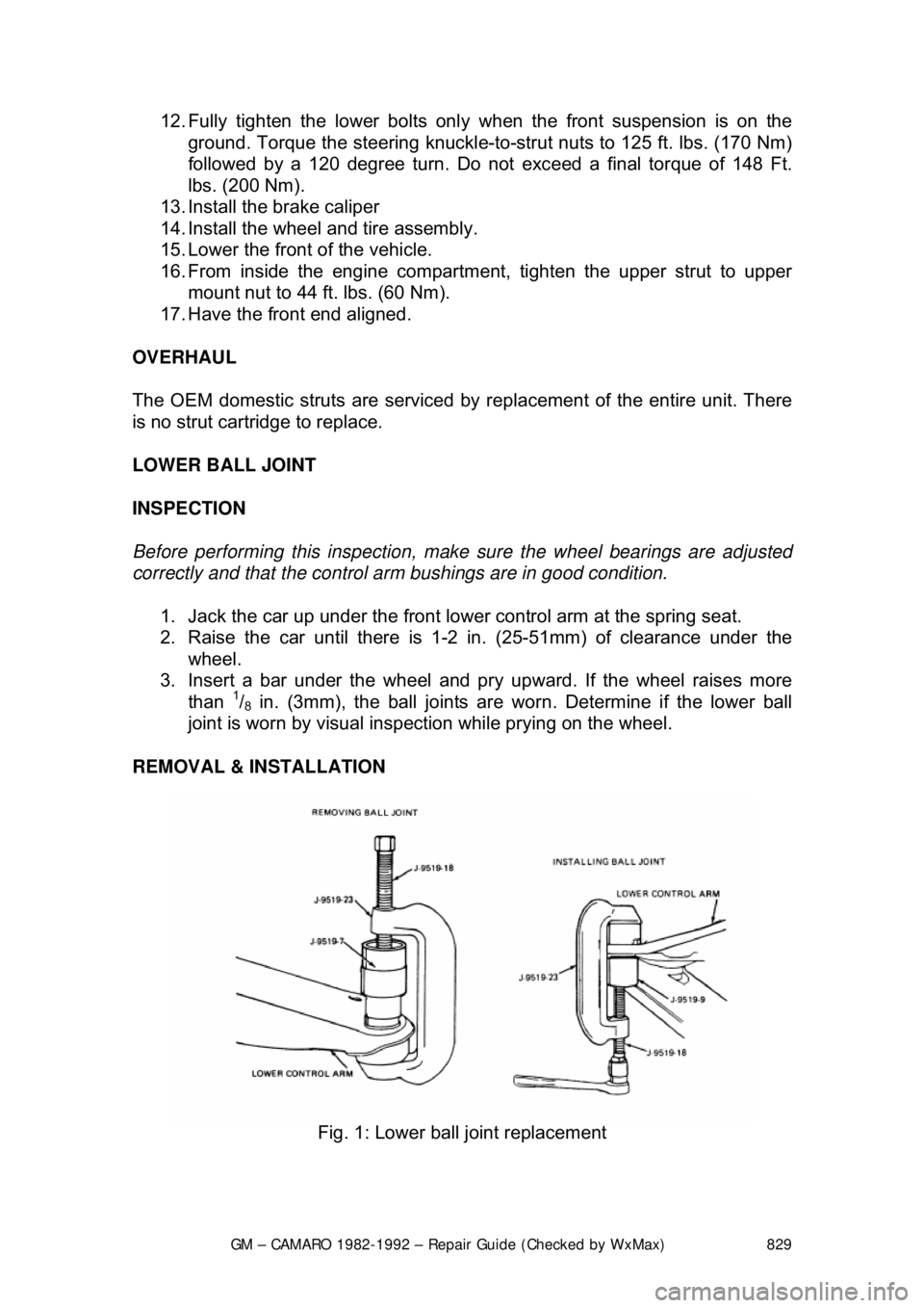
LOWER BALL JOINT
INSPECTION
Before performing this inspection, make sure the wheel bearings are adjusted
correctly and that the control arm bushings are in good condition.
1. Jack the car up under the front lower control arm at the spring seat.
2. Raise the car until t here is 1-2 in. (25-51mm) of clearance under the
wheel.
3. Insert a bar under the wheel and pr y upward. If the wheel raises more
than
1/8 in. (3mm), the ball joints are worn. Determine if the lower ball
joint is worn by visual inspec tion while prying on the wheel.
REMOVAL & INSTALLATION
Fig. 1: Lower ball joint replacement
Page 832 of 875

GM – CAMARO 1982-1992 – Repair Guide (Checked by WxMax) 832
6. Hold the stabilizer shaft approximat
ely 55mm from the bottom of the side
rail and torque the bracket bolts to 37 ft. lbs. (50 Nm).
7. Install the bolt, nut, grommets, spacer and retainers.
8. Lower the car.
LOWER CONTROL ARM
REMOVAL & INSTALLATION 1. Raise the car and safely support on jackstands.
2. Remove the wheel and tire.
3. Remove the stabilizer link and bush ings at the lower control arm.
4. Remove the pivot bolt nuts. DO NOT re move the pivot bolts at this time.
5. Install tool J-23028 or equivalent adapter to the jack and place into
position with tool J-23028 or equival ent adapter supporting bushings.
6. Install the jackstand under the outsi de frame rail on the opposite side of
the vehicle.
7. Raise tool J-23028 or equivalent adapter enough to remove both pivot
bolts.
8. Lower tool J-23028 or equivalent adapter.
9. Remove the spring and insulato r tape insulator to the spring.
10. Remove the ball joint from the knuckle.
11. To install, reverse the removal procedure.
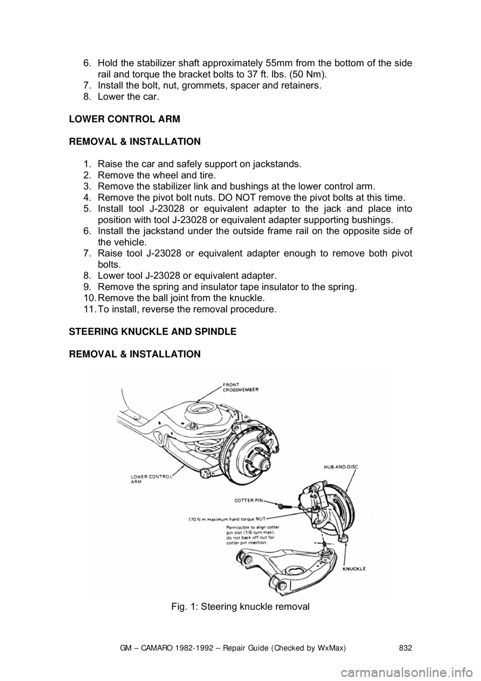
STEERING KNUCKLE AND SPINDLE
REMOVAL & INSTALLATION
Fig. 1: Steering knuckle removal
Page 845 of 875
GM – CAMARO 1982-1992 – Repair Guide (Checked by WxMax) 845
STABILIZER (SWAY) BAR
REMOVAL & INSTALLATION
Fig. 1: Stabilizer end links
1. Raise and support the rear end on jackstands.
2. Disconnect the end link bolts.
3. Remove the U-bolts and insulators.
4. Installation is the reverse of re moval. Please refer to the torque
specifications chart.
STEERING COLUMN
WARNING - Before attempting any repairs involving the steering wheel or
disassembly of it, ensure that the Supple mental Inflatable Restraint (Air Bag)
system is properly disarmed.
Page:
< prev 1-8 9-16 17-24