1982 CHEVROLET CAMARO battery
[x] Cancel search: batteryPage 755 of 875

GM – CAMARO 1982-1992 – Repair Guide (Checked by WxMax) 755
16. With the aid of an assistant, posit
ion and support the fuel tank with the
straps. Loosely install the front fuel tank attaching bolts.
17. Engage the electrical connection.
18. Connect the fuel hoses and li nes separated during removal.
19. Install the muffler heat sh ield and the exhaust system.
20. Install the rear axle and the fuel filler neck shield.
21. Lower the vehicle.
22. Add fuel and install the filler cap.
23. Connect the negative battery cable.
24. With the engine OFF, turn the igni tion switch to the ON position for 2
seconds, then turn it to the OFF positi on for 10 seconds. Again turn it to
the ON position and check for fuel leaks.
SENDING UNIT REPLACEMENT 1. Remove the fuel tank.
2. Clean the area surrounding t he sender assembly to prevent
contamination of the fuel system.
3. Using tool J-24187 or equivalent, re move the sending unit retaining cam.
Remove the fuel sender and O-rings fr om the tank. Discard the O-rings.
4. If necessary, separate the fuel pum p from the sending unit assembly.
To install: 5. If removed, install the fuel pump to the sending unit. If the strainer was
removed, it must be re placed with a new one.
6. Inspect and clean the O-ring mating surfaces.
7. Install a new O-ring in the groove around the tank opening. If applicable,
install a new O-ring on t he fuel sender feed tube.
8. Install the fuel sender assembly as follows: a. The fuel pump strainer must be in a horizontal position, and when
installed, must not block the travel of the float arm. Gently fold the
strainer over itself an d slowly position the sending assembly in the
tank so the strainer is not dam aged or trapped by the sump walls.
9. Install the retaining cam us ing tool J-24187 or equivalent.
10. Install the fuel tank assembly.
Page 763 of 875

GM – CAMARO 1982-1992 – Repair Guide (Checked by WxMax) 763
•
Jackstands for support.
• Oil filter wrench.
• Spout or funnel for pouring fluids.
• Grease gun for chassis lubrication (unl ess your vehicle is not equipped
with any grease fittings)
• Hydrometer for checking the battery (unless equipped with a sealed,
maintenance-free battery).
• A container for draining oil and other fluids.
• Rags for wiping up the inevitable mess.
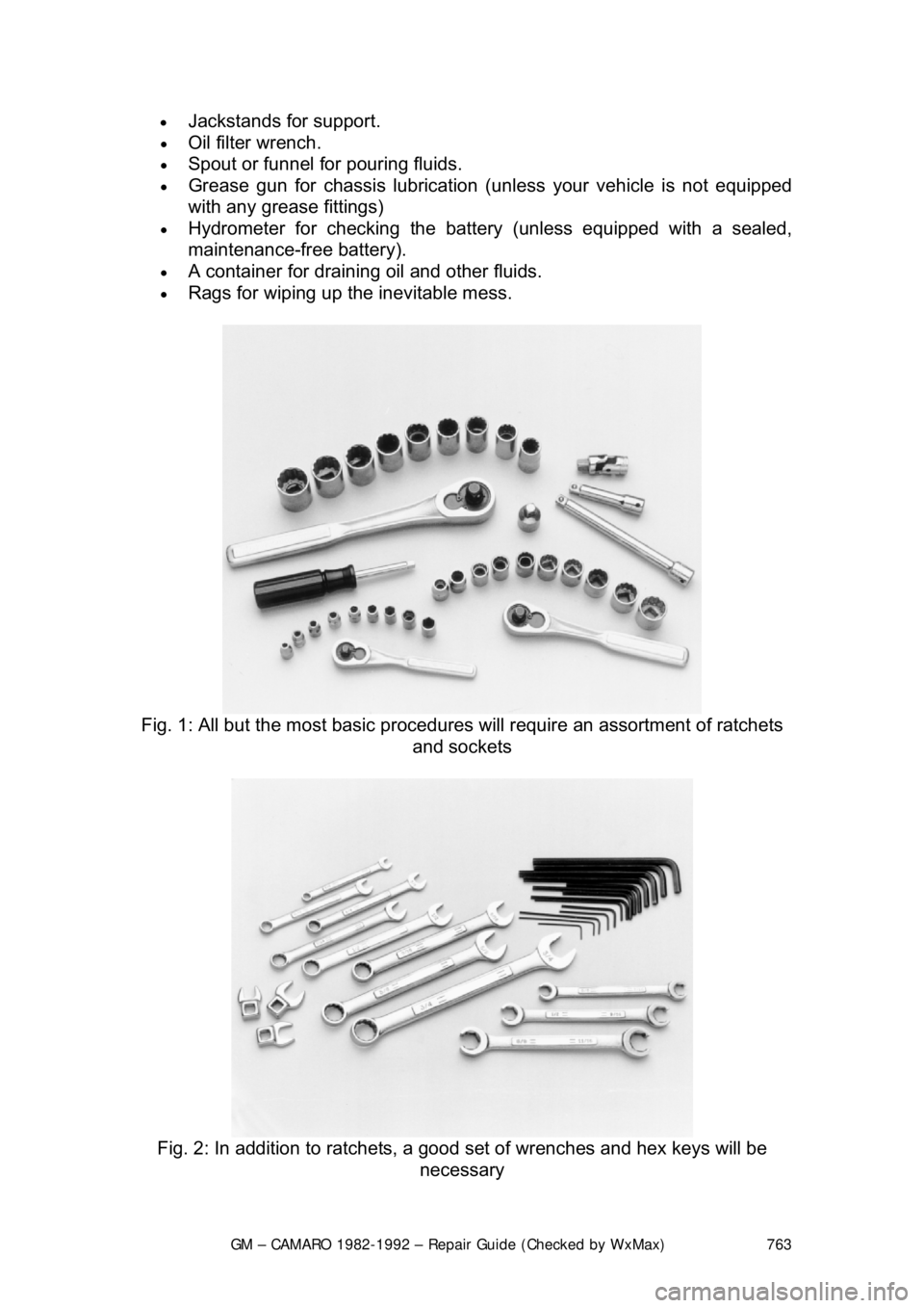
Fig. 1: All but the most basic procedures will require an assortment of ratchets
and sockets
Fig. 2: In addition to ratchets, a good set of wrenches and hex keys will be
necessary
Page 771 of 875

GM – CAMARO 1982-1992 – Repair Guide (Checked by WxMax) 771
A more advanced set of tools, suit
able for tune-up work, can be drawn up
easily. While the tools are slightly more sophisticated, they need not be
outrageously expensive. There are severa l inexpensive tach/dwell meters on
the market that are every bit as good for the average mechanic as a
professional model. Just be sure that it goes to a least 1200-1500 rpm on the
tach scale and that it works on 4, 6 and 8-cylinder engines. The key to these
purchases is to make them with an eye towards adaptability and wide range. A
basic list of tune-up tools could include:
• Tach/dwell meter.
• Spark plug wrench and gapping tool.
• Feeler gauges for valve adjustment.
• Timing light.
The choice of a timing light should be made carefully. A light which works on the
DC current supplied by the vehicle's battery is the best choice; it should have a
xenon tube for brightness. On any vehi cle with an electronic ignition system, a
timing light with an inductive pickup that clamps around the No. 1 spark plug
cable is preferred.
In addition to these basic tools, ther e are several other tools and gauges you
may find useful. These include:
• Compression gauge. The screw-in type is slower to use, but eliminates
the possibility of a faulty r eading due to escaping pressure.
• Manifold vacuum gauge.
• 12V test light.
• A combination volt/ohmmeter
• Induction Ammeter. This is used for determining whether or not there is
current in a wire. These are handy fo r use if a wire is broken somewhere
in a wiring harness.
As a final note, you will probably find a torque wrench necessary for all but the
most basic work. The beam type models are perfectly adequate, although the
newer click types (breakaway) are eas ier to use. The click type torque
wrenches tend to be more expensive. Also keep in mind that all types of torque
wrenches should be periodically checked a nd/or recalibrated. You will have to
decide for yourself which better fits your pocketbook, and purpose.
SPECIAL TOOLS
Normally, the use of special factory tool s is avoided for repair procedures, since
these are not readily available for the do-it-yourself mechanic. When it is
possible to perform the job with more co mmonly available tools, it will be
pointed out, but occasionally, a special t ool was designed to perform a specific
function and should be used. Before s ubstituting another tool, you should be
convinced that neither your safety nor the performance of the vehicle will be
compromised.
Page 810 of 875

GM – CAMARO 1982-1992 – Repair Guide (Checked by WxMax) 810
Fig. 14: After the bearings are adjusted, install the dust cap by gently tapping on
the flange - DO NOT damage the c ap by hammering on the center
JUMP STARTING A DEAD BATTERY
Whenever a vehicle is jump started, pr ecautions must be followed in order to
prevent the possibility of personal inju ry. Remember that batteries contain a
small amount of explosive hydrogen gas which is a by-product of battery
charging. Sparks should always be av oided when working around batteries,
especially when attaching jumper cabl es. To minimize the possibility of
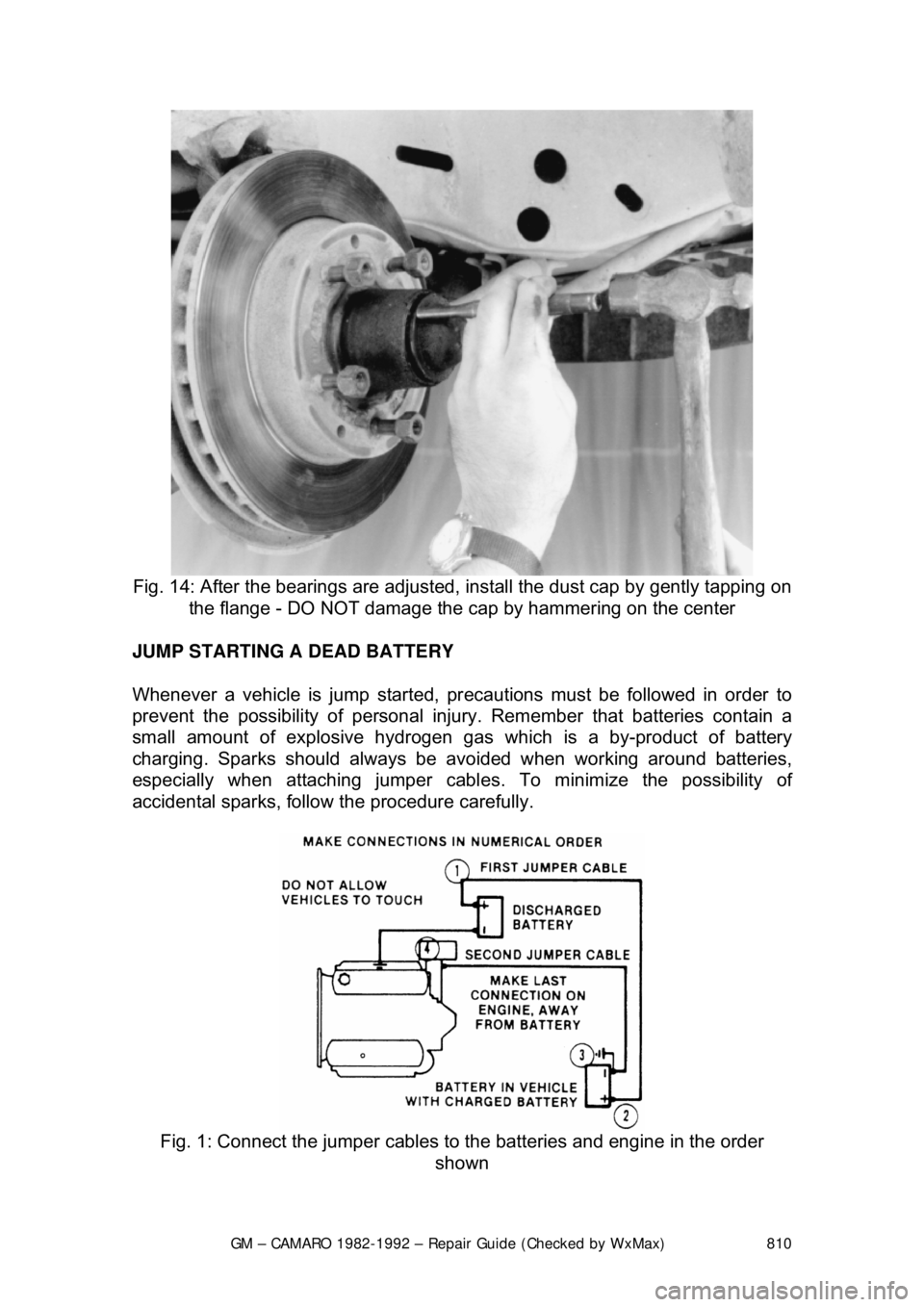
accidental sparks, follow the procedure carefully.
Fig. 1: Connect the jumper cables to the batteries and engine in the order
shown
Page 811 of 875

GM – CAMARO 1982-1992 – Repair Guide (Checked by WxMax) 811
CAUTION
- NEVER hook the batteries up in a series circuit or the entire
electrical system will go up in smoke, including the starter!
Vehicles equipped with a diesel engine may utilize two 12 volt batteries. If so,
the batteries are connected in a parallel circuit (positive terminal to positive
terminal, negative terminal to negative te rminal). Hooking the batteries up in
parallel circuit increases battery cranki ng power without increasing total battery
voltage output. Output remains at 12 vo lts. On the other hand, hooking two 12
volt batteries up in a series circuit (positive terminal to negative terminal,
positive terminal to negative terminal) incr eases total battery output to 24 volts
(12 volts plus 12 volts).
JUMP STARTING PRECAUTIONS
• Be sure that both batteries are of t he same voltage. Vehicles covered by
this information and most vehicles on the road today utilize a 12 volt
charging system.
• Be sure that both batteries are of the same polarity (have the same
terminal, in most cases NEGATIVE grounded).
• Be sure that the vehicles are not touching or a short could occur.
• On serviceable batteries, be sure the v ent cap holes are not obstructed.
• Do not smoke or allow sparks anywhere near the batteries.
• In cold weather, make sure the battery electrolyte is not frozen. This can
occur more readily in a battery that has been in a state of discharge.
• Do not allow electrolyte to c ontact your skin or clothing.
JUMP STARTING PROCEDURE 1. Make sure that the voltages of the 2 batteries are the same. Most
batteries and charging systems are of the 12 volt variety.
2. Pull the jumping vehicle (with t he good battery) into a position so the
jumper cables can reach the dead battery and that vehicle's engine.
Make sure that the ve hicles do NOT touch.
3. Place the transmissions of both vehicles in Neutral (MT) or P (AT), as
applicable, then firmly set their parking brakes.
If necessary for safety reasons, the hazard lights on both vehicles may be
operated throughout the entir e procedure without significantly increasing the
difficulty of jumping the dead battery.
4. Turn all lights and accessories OFF on both vehicles. Make sure the ignition switches on both vehicles are turned to the OFF position.
5. Cover the battery cell caps with a rag, but do not cover the terminals.
6. Make sure the terminals on both batte ries are clean and free of corrosion
or proper electrical connection wil l be impeded. If necessary, clean the
battery terminals before proceeding.
7. Identify the positive (+) and negat ive (-) terminals on both batteries.
8. Connect the first jumper cable to the positive (+) terminal of the dead
battery, then connect the other end of that cable to the positive (+)
terminal of the booster (good) battery.
Page 812 of 875

GM – CAMARO 1982-1992 – Repair Guide (Checked by WxMax) 812
9. Connect one end of the other jumper
cable to the negative (-) terminal on
the booster battery and the final cable clamp to an engine bolt head,
alternator bracket or ot her solid, metallic point on the engine with the
dead battery. Try to pick a ground on the engine that is positioned away
from the battery in order to minimi ze the possibility of the 2 clamps
touching should one l oosen during the procedure. DO NOT connect this
clamp to the negative (-) term inal of the bad battery.
CAUTION - Be very careful to keep the jum per cables away from moving parts
(cooling fan, belts, etc.) on both engines.
10. Check to make sure that the c ables are routed away from any moving
parts, then start the d onor vehicle's engine. Run the engine at moderate
speed for several minutes to allow the dead battery a chance to receive
some initial charge.
11. With the donor vehicle's engine still r unning slightly above idle, try to start
the vehicle with the dead battery. Crank the engine for no more than 10 \
seconds at a time and let the starter cool for at least 20 seconds between
tries. If the vehicl e does not start in 3 tries, it is likely that something else
is also wrong or that the battery needs additional time to charge.
12. Once the vehicle is star ted, allow it to run at idle for a few seconds to
make sure that it is operating properly.
13. Turn ON the headlight s, heater blower and, if equipped, the rear
defroster of both vehicles in order to reduce the severity of voltage spikes
and subsequent risk of dam age to the vehicles' electrical systems when
the cables are disconnected. This st ep is especially important to any
vehicle equipped with computer control modules.
14. Carefully disconnect the cables in the reverse order of connection. Star\
t with the negative cable that is attached to the engine ground, then the
negative cable on the donor battery. Di sconnect the positive cable from
the donor battery and finally, disconnect the positive cable from the
formerly dead battery. Be careful when disconnecting the cables from the
positive terminals not to allow the alli gator clips to touch any metal on
either vehicle or a short and sparks will occur.
JACKING
Your vehicle was supplied with a jack for emergency road repairs. This jack is
fine for changing a flat tire or other s hort term procedures not requiring you to
go beneath the vehicle. If it is used in an emergency situation, carefully follow
the instructions provided eit her with the jack or in your owner's manual. Do not
attempt to use the jack on any portions of the vehicle other than specified by the
vehicle manufacturer. Always block the diagonally opposite wheel when using a
jack.
A more convenient way of jacking is the use of a garage or floor jack. You may
use the floor jack to raise the vehicle in the areas shown in the illustration .
Page 848 of 875

GM – CAMARO 1982-1992 – Repair Guide (Checked by WxMax) 848
1982-89 VEHICLES
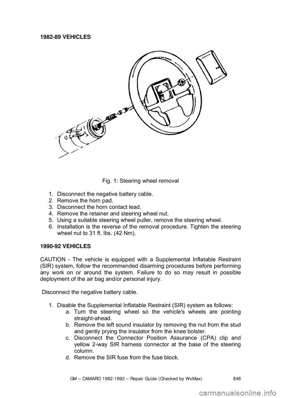
Fig. 1: Steering wheel removal
1. Disconnect the negative battery cable.
2. Remove the horn pad.
3. Disconnect the horn contact lead.
4. Remove the retainer and steering wheel nut.
5. Using a suitable steering wheel pu ller, remove the steering wheel.
6. Installation is the reverse of the removal procedure. Tighten the steering
wheel nut to 31 ft. lbs. (42 Nm).
1990-92 VEHICLES
CAUTION - The vehicle is equipped with a Supplemental Inflatable Restraint
(SIR) system, follow the recommended disarming procedures before performing
any work on or around the system. Failure to do so may result in possibl\
e
deployment of the air bag and/or personal injury.
Disconnect the negative battery cable.
1. Disable the Supplemental Inflatable Restraint (SIR) system as follows:
a. Turn the steering wheel so th e vehicle's wheels are pointing
straight-ahead.
b. Remove the left sound insulator by removing the nut from the stud
and gently prying the insulator from the knee bolster.
c. Disconnect the Connector Position Assurance (CPA) clip and yellow 2-way SIR harness connecto r at the base of the steering
column.
d. Remove the SIR fuse from the fuse block.
Page 849 of 875

GM – CAMARO 1982-1992 – Repair Guide (Checked by WxMax) 849
2. Loosen the screws and lo
cknuts from the back of the steering wheel
using a suitable Torx® driver or equi valent, until the inflator module can
be released from the steering wheel. Remove the inflator module from
the steering wheel.
CAUTION - When carrying a live inflator modul e, ensure the bag and trim cover
are pointed away from the body. In ca se of an accidental deployment, the bag
will then deploy with minima l chance of injury. When placing a live inflator
module on a bench or other surface, a lways place the bag and trim cover up,
away from the surface. This is necessa ry so a free space is provided to allow
the air bag to expand in the unlikely event of accidental deployment. Otherwise,
personal injury may result. Also, never carry the inflator module by the wires or
connector on the underside of the module.
4. Disconnect the coil assembly connec tor and CPA clip from the inflator
module terminal.
5. Remove the steering wheel locking nut.
6. Using a suitable pulle r, remove the steering wheel and disconnect the
horn contact. When attaching the steer ing wheel puller, use care to
prevent threading the side screws into the coil assembly and damaging
the coil assembly.
To install: 7. Route the coil assembly connec tor through the steering wheel.
8. Connect the horn contact and install the steering wheel. When installing
the steering wheel, ali gn the block tooth on the steering wheel with the
block tooth on the steering shaft within 1 female serration.
9. Install the steering wheel locking nu t. Tighten the nut to 31 ft. lbs. (42
Nm).
10. Connect the coil assembly connector and CPA clip to the inflator module
terminal.
11. Install the inflator module. Ensu re the wiring is not exposed or trapped
between the inflator modul e and the steering wheel. Tighten the inflator
module screws to 25 inch lbs. (2.8 Nm).
12. Connect the negative battery cable.
13. Enable the SIR system as follows: a. Connect the yellow 2-way SIR harness connector to base of the steering column and CPA.
b. Install the left sound insulator.
c. Install the SIR fuse in the fuse block.
d. Turn the ignition switch to the RUN position and verify that the
inflatable restraint indicator fl ashes 7-9 times and then turns OFF.
If the indicator does not respond as stated, a problem within the
SIR system is indicated.