1982 CHEVROLET CAMARO battery
[x] Cancel search: batteryPage 717 of 875

GM – CAMARO 1982-1992 – Repair Guide (Checked by WxMax) 717
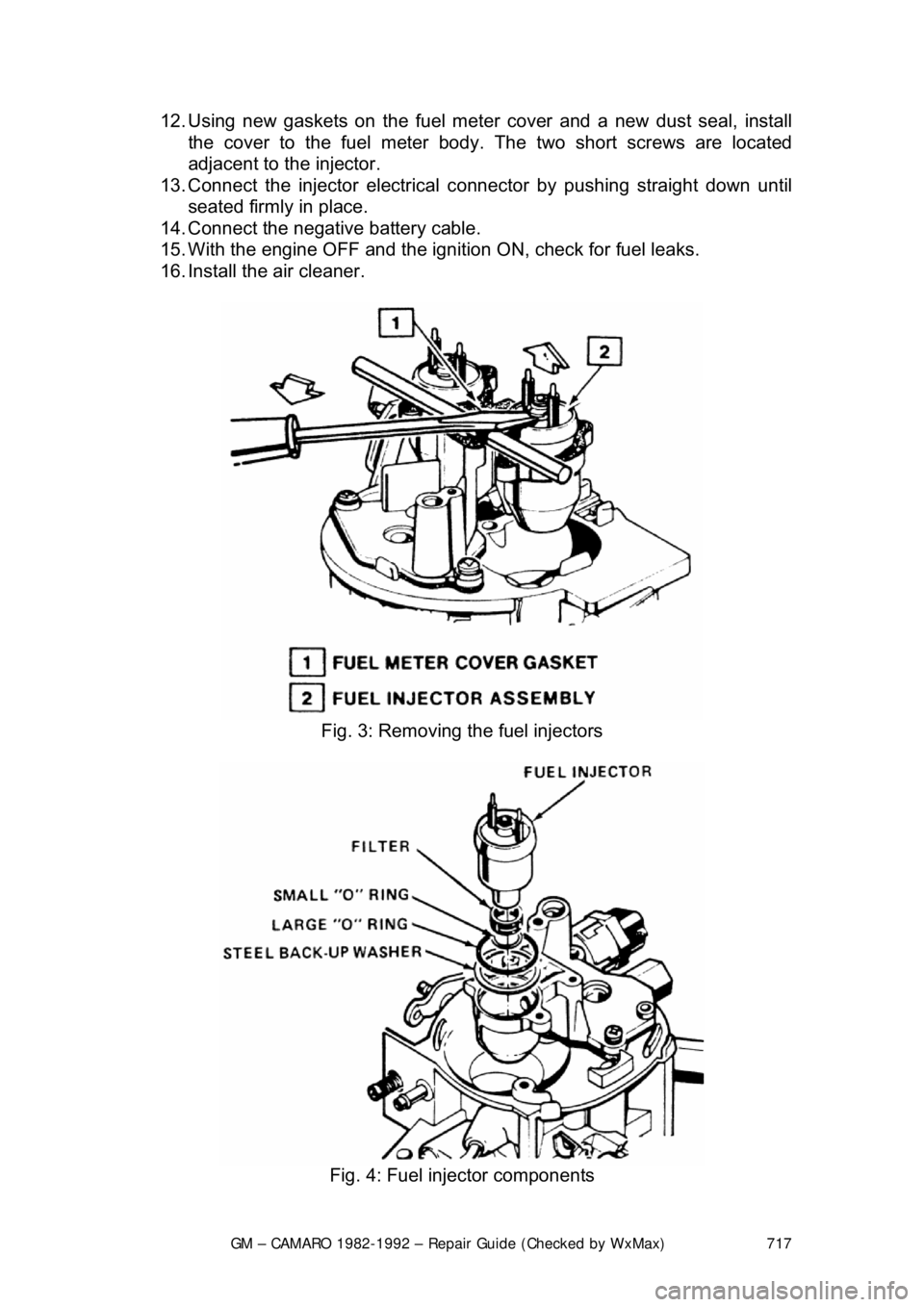
12. Using new gaskets on the fuel mete
r cover and a new dust seal, install
the cover to the fuel meter body . The two short screws are located
adjacent to the injector.
13. Connect the injector electrical c onnector by pushing straight down until
seated firmly in place.
14. Connect the negative battery cable.
15. With the engine OFF and the igniti on ON, check for fuel leaks.
16. Install the air cleaner.
Fig. 3: Removing the fuel injectors
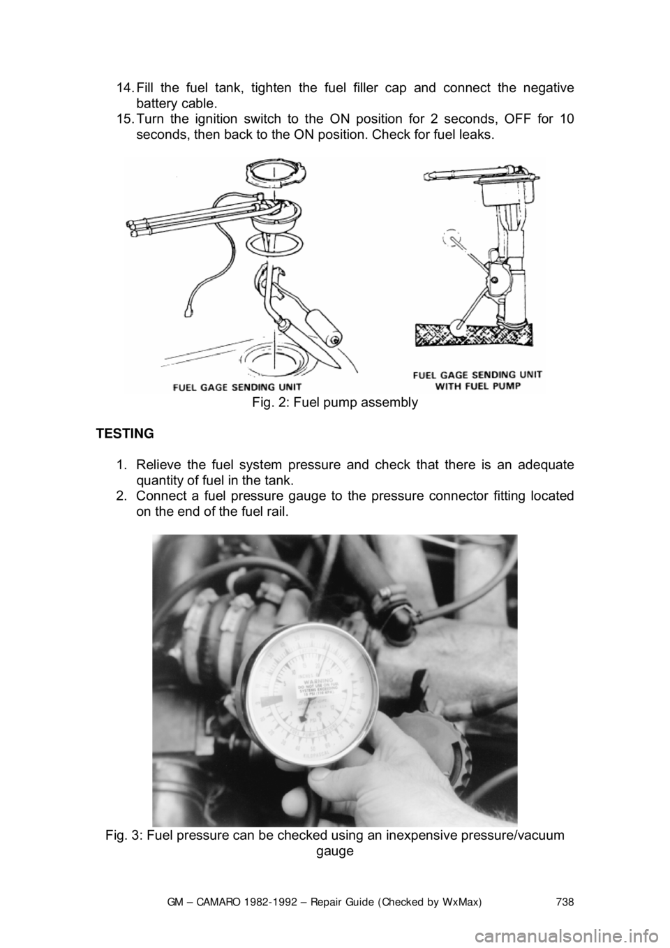
Fig. 4: Fuel injector components
Page 719 of 875

GM – CAMARO 1982-1992 – Repair Guide (Checked by WxMax) 719
11. Lubricate the new large O-ring with cl
ean engine oil and install it directly
over the backup washer. Be sure t he O-ring is seated properly and is
flush with the top of the fuel meter body surface.
12. Lubricate the new small O-ring with clean engine oil and install it on the
nozzle end of the injector. Push t he O-ring on far enough to contact the
filter.
WARNING - Do not attempt to reverse this procedure and install the backup
washer and O-ring after the injector is located in the cavity. To do so will
prevent proper seating of the O-ring in th e cavity recess which could result in a
fuel leak and possible fire.
13. Install the injector by aligning the raised lug on the injector base with the
notch cast into the fuel meter body . Push down on the injector making
sure it is fully seated in the cavity. In jector installation is correct when the
lug is seated in the notch and the electrical terminals are parallel to the
throttle shaft.
14. Using new gaskets on the fuel mete r cover and a new dust seal, install
the cover to the fuel meter body. Use an appropriate thread locking
compound on the cover attaching screws.
15. Connect the injector electrical c onnector by pushing straight down until
seated firmly in place.
16. Connect the negative battery cable.
17. With the engine OFF and the igniti on ON, check for fuel leaks.
18. Install the air cleaner.
ADJUSTMENTS
MINIMUM IDLE SPEED
Minimum idle speed should only be adjus ted when installing a replacement
throttle body. The idle stop screw is used to regulate the minimum idle speed of
the engine. The throttle body is adjusted at the factory, then covered with a cap
or plug to discourage unnecessary readjustment.
2.5L ENGINES 1. Remove the air cleaner and pl ug the THERMAC vacuum port.
2. Disconnect the TV cable from the th rottle control bracket to allow access
to the idle adjustment screw.
3. Remove the throttle stop screw plug or cap.
4. Connect a tachometer to the engine.
5. Disconnect the Idle Air Control (IAC) valve connector.
6. Start the engine with the transmi ssion in PARK (auto transmission) or
NEUTRAL (manual transmission) and allow the engine speed to
stabilize. All accessories (A/C, rear defogger, etc.) should be OFF.
7. Install tool J-33047 in t he idle air passage of the throttle body. Be certain
that the tool seats fully in t he passage and no air leaks exist.
Page 726 of 875

GM – CAMARO 1982-1992 – Repair Guide (Checked by WxMax) 726
RELIEVING FUEL SYSTEM PRESSURE
1. Remove the fuse marked "Fuel Pu mp" from the fuse block in the
passenger compartment.
2. Crank the engine. Th e engine will start and run until the fuel supply
remaining in the lines is exhauste d. When the engines stops, engage the
starter again for three seconds to a ssure dissipation of any remaining
pressure.
3. With the ignition OFF, disconnect the negative battery cable to prevent
fuel discharge if the key is accidentally turned to the ON position.
Replace the fuse with the ignition OFF.
When disconnecting fuel lines, there ma y still be a small amount of fuel
released. Cover the fuel line connection wi th a shop cloth to collect the fuel,
then place the cloth in an approved container.
ELECTRIC FUEL PUMP
REMOVAL & INSTALLATION
The removal and installation procedures fo r the Crossfire injection system fuel
pump is identical to the Throttle Body In jection (TBI) system. Please refer to the
TBI fuel pump procedures earlier in this repair guide.
TESTING
The testing procedures for the Crossfire in jection system fuel pump is identical
to the Throttle Body Injection (TBI) syst em. Please refer to the TBI fuel pump
procedures earlier in this repair guide.
THROTTLE BODY
REMOVAL & INSTALLATION
FRONT UNIT
1. Relieve the fuel system pressure.
2. Remove the air cleaner assembly, noting the connection points of the
vacuum lines.
3. Detach the electrical connectors at the injector and the idle air control
motor.
4. Disconnect the vacuum lines from the TBI unit, noting the connection
points. During installation, refer to the underhood emission control
information decal for vacuum line routing information.
5. Disconnect the transmission det ent cable from the TBI unit.
6. Disconnect the fuel inlet (feed) and fuel balance line connections at the
front TBI unit.
7. Remove and discard the throttle cont rol rod retaining clip from the front
TBI throttle lever stud. A new clip must be used during reassembly.
8. Unbolt and remove the TBI unit.
Page 736 of 875

GM – CAMARO 1982-1992 – Repair Guide (Checked by WxMax) 736
The mass air flow systems measure the
mass of air that is drawn into the
engine cylinders, rather than just the vo lume. The sensor contains a hot-wire
sensing unit, which is made up of an electronic balanced bridge network.
Whenever current is suppli ed to the sensor, the bridge is energized and the
sensing hot-wire is heated. As the air enter s the mass air flow sensor, it passes
over and cools the hot wire. When the hot wire is cooled, it's resistance changes
and additional current is needed to k eep the bridge network balanced. This
increase in current is sent to the computer as a voltage signal and is used to
calculate the mass of the incoming air. The ECM uses this information to\
determine the duration of fuel injection pulse, ignition timing and EGR operation.
The speed density systems calculate the volume of air moving through the
intake. The ECM establishes the speed fact or through a signal from the ignition
module. The Manifold or Intake Air Temperature (MAT/IAT) and the Engine
Coolant Temperature (ECT) sensors work together to assure that proper
temperature information gets to the ECM wh ile the Manifold Absolute Pressure
(MAP) sensor monitors the changes in m anifold pressure which results from
changes in engine loading. These three se nsors contribute to the density factor.
Together, these inputs (engine speed, coolant temperature sensor, etc ...) are
the major determinants of the air/fuel mixture delivered by the fuel injection
system.
The following engines and fuel managem ent systems are covered in this
section:
• 1985-1989 2.8L MPFI - Mass Air Flow
• 1990-1992 3.1L MPFI - Speed Density
• 1985-1989 5.0L and 5.7L TPI - Mass Air Flow
• 1990-1992 5.0L and 5.7L TPI - Speed Density
Relieving Fuel System Pressure
1. Disconnect the negative battery cable to prevent fuel discharge if the key
is accidentally turned to the RUN position.
2. Loosen the fuel filler cap to reliev e the tank pressure and do not tighten
until service has been completed.
3. Connect J-34730-1 fuel pressure gauge or equivalent, to the fuel
pressure test valve. Wrap a shop towel around the fitting while
connecting the gauge to prevent spillage.
4. Place the end of the bleed hose into a suitable container and open the
valve to relieve the fuel system pressure.
ELECTRIC FUEL PUMP
REMOVAL & INSTALLATION
The fuel pump is part of t he fuel sender assembly located inside the fuel tank.
Page 737 of 875

GM – CAMARO 1982-1992 – Repair Guide (Checked by WxMax) 737
1. Release the fuel syst
em pressure and disconnec t the negative battery
cable.
2. Drain the fuel tank, then raise and safely support the vehicle.
3. Remove the fuel tank from the vehicle.
4. Clean the area surrounding t he sender assembly to prevent
contamination of the fuel system.
5. Using tool J-24187 or equivalent, re move the sending unit retaining cam.
Remove the fuel sender and O-rings fr om the tank. Discard the O-rings.
Fig. 1: A special tool is usually availa ble to remove or install the fuel pump
locking cam
6. If necessary, separate the fuel pum p from the sending unit assembly.
To install: 7. If removed, install the fuel pump to the sending unit. If the strainer was
removed, it must be re placed with a new one.
8. Inspect and clean the O-ring mating surfaces.
9. Install a new O-ring in the groove around the tank opening. If applicable,
install a new O-ring on t he fuel sender feed tube.
10. Install the fuel sender assembly as follows: a. The fuel pump strainer must be in a horizontal position, and when
installed, must not block the travel of the float arm. Gently fold the
strainer over itself an d slowly position the sending assembly in the
tank so the strainer is not dam aged or trapped by the sump walls.
11. Install the retaining cam us ing tool J-24187 or equivalent.
12. Install the fuel tank assembly.
13. Lower the vehicle.
Page 738 of 875

GM – CAMARO 1982-1992 – Repair Guide (Checked by WxMax) 738
14. Fill the fuel tank, tighten the f
uel filler cap and connect the negative
battery cable.
15. Turn the ignition switch to t he ON position for 2 seconds, OFF for 10
seconds, then back to the ON posit ion. Check for fuel leaks.
Fig. 2: Fuel pump assembly
TESTING 1. Relieve the fuel system pressure and check that there is an adequate
quantity of fuel in the tank.
2. Connect a fuel pressure gauge to the pressure connector fitting located
on the end of the fuel rail.
Fig. 3: Fuel pressure can be check ed using an inexpensive pressure/vacuum
gauge
Page 739 of 875

GM – CAMARO 1982-1992 – Repair Guide (Checked by WxMax) 739
3. Make sure the ignition switch has
been in the OFF position for at least 10
seconds and that all accessories are OFF.
4. Turn the ignition switch ON and the pump will run for about 2 seconds.
Note the system pressure with t he pump running, it should be between
40-47 psi.
The ignition switch may have to be cycled to the ON position more than once to
obtain maximum pressure. It is also norma l for the pressure to drop slightly
when the pump first stops, but it should then hold steady.
5. If the pressure is not as specified, verify that fuel pump operation is
heard in the tank.
6. If fuel pump operation is not heard, inspect the fuel pump relay and
wiring.
7. If fuel pump operation is heard, inspect the filter and lines for restriction.
8. Start the engine and make sure the pr essure decreases about 3-10 psi at
idle.
9. If fuel pressure does not decrease, inspect the fuel pressure regulator
and hose.
10. Disconnect the fuel pressure gauge.
THROTTLE BODY
REMOVAL & INSTALLATION 1. Disconnect the negative (-) battery c able and partially drain the radiator.
2. Remove the air inlet duct and unplug the IAC and TPS electrical connectors.
3. Label and disconnect the vacuum and coolant lines.
4. Disconnect the accelerator, thro ttle valve (transmission control) and
cruise control cables, as applicable.
5. Remove the throttle body attaching bolts, then separate the throttle body from the plenum.
6. Discard the gasket.
To install: 7. Install the throttle body to the plenum using a new gasket. Tighten the \
bolts to specification.
8. Engage the accelerator, throttle valve and cruise control cables, as
necessary. Make sure that the link ages do not hold the throttle open.
9. Connect the vacuum and coolant lines.
10. Install the air inlet duct and plug the IAC and TPS electrical connectors
into their sockets.
11. Connect the negative (-) battery cable and refill the radiator.
12. With the engine OFF, check to s ee that the accelerator pedal is free.
Depress the pedal to the floor and release.
Page 742 of 875

GM – CAMARO 1982-1992 – Repair Guide (Checked by WxMax) 742
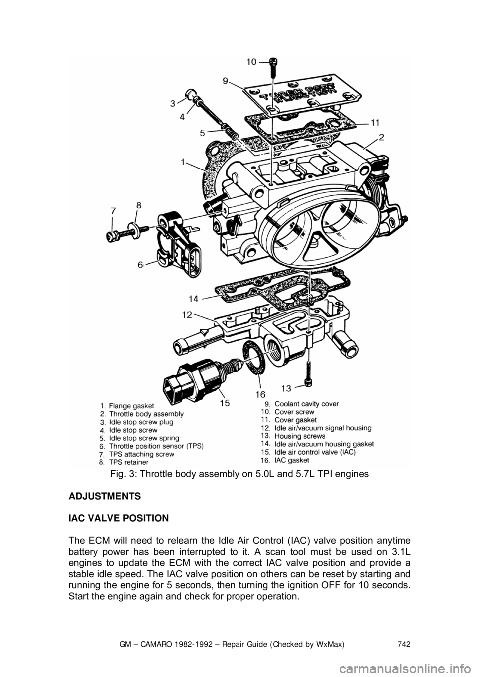
Fig. 3: Throttle body assembly on 5.0L and 5.7L TPI engines
ADJUSTMENTS
IAC VALVE POSITION
The ECM will need to relearn the Idle Ai r Control (IAC) valve position anytime
battery power has been interrupted to it. A scan tool must be used on 3.1L
engines to update the ECM with the corre ct IAC valve position and provide a
stable idle speed. The IAC valve position on others can be reset by starting and
running the engine for 5 seconds, then turning the ignition OFF for 10 seconds.
Start the engine again and che ck for proper operation.