1982 CHEVROLET CAMARO wheel bolt torque
[x] Cancel search: wheel bolt torquePage 359 of 875

GM – CAMARO 1982-1992 – Repair Guide (Checked by WxMax) 359
3. Disconnect all wiring from the star
ter solenoid. Replace each nut as the
connector is removed (as thread sizes differ from connector to
connector). Note or tag the wiring positions for installation.
4. Remove the bracket from the st arter and the two mounting bolts. On
engines with a solenoid heat shield, remove the front bracket upper bolt
and detach the bracket fr om the starter.
5. Remove the front bracket bolt or nut. Lower the starter front end first, and
then remove the unit from the car.
To install: 6. Position the starter into place and se cure it with the front bracket bolt and
nut. Torque the two mounting bolts to 25-35 ft. lbs.
CAUTION - If shims were removed, they must be replaced to ensure proper
pinion-to-flywheel engagement.
7. On engines with a solenoid heat shield, attach the bracket to the starter.
Install the bracket to the starter and the two mounting bolts. Install the
front bracket upper bolt.
8. Connect all wiring to the starte r solenoid and tighten the nuts.
9. Lower the vehicle.
10. Connect the negative battery cable.
SOLENOID REPLACEMENT 1. Remove the screw and washer from the motor connector strap terminal.
2. Remove the two solenoid retaining screws.
3. Twist the solenoid housing clockwis e to remove the flange key from the
keyway in the housing. Then remove the housing.
4. To re-install the unit, place the re turn spring on the plunger and place the
solenoid body on the driv e housing. Turn counterclockwise to engage the
flange key. Place the two retaining screws in position and install the
screw and washer which secures the strap terminal. Install the unit on
the starter.
SENDING UNITS AND SENSORS
For additional information on engine sensors, refer to Engine Performance &
Tune-up and Engine Controls in this repair guide.
Page 424 of 875

GM – CAMARO 1982-1992 – Repair Guide (Checked by WxMax) 424
11. Clean all old RTV from the mating surfaces.
12. Install the rear gasket into the
rear main bearing cap and apply a small
amount of RTV where the gasket engages into the engine block.
13. Install the front gasket.
14. Install the side gaskets, using grease as a retainer. Apply a small amount
of RTV where the side gaskets meet the front gasket.
15. Install the oil pan.
Install the oil pan-to-timing cover bolts la st, as these holes will not align until the
other pan bolts are snug.
16. Torque the pan bolts to 53 inch lbs. (6 Nm) for 1982-1985 models and 90
inch lbs. (10 Nm) for 1986 models.
17. Lower the engine and install the fr ont mount through-bolts. Torque bolts
to 48 ft lbs. (65 Nm).
18. Install the flywheel dust cover.
19. Install the starter assembly.
20. Connect the exhaust pipe at the manifold.
21. Tighten the exhaust pipe hanger bracket.
22. Lower the vehicle.
23. Connect the negative battery cable at the battery.
24. Fill the engine with engine oil and start engine. Check for leaks.
OIL PUMP
REMOVAL & INSTALLATION
Fig. 1: Oil pump - V8
Page 456 of 875

GM – CAMARO 1982-1992 – Repair Guide (Checked by WxMax) 456
2. Drain the engine oil and remove the oil pan.
3. Remove the rear main bearing cap.
4. Insert packing tool J-29114-2 or equi
valent, against 1 end of the seal in
the cylinder block. Drive the old seal gently into the groove until it is
packed tight. This will vary from
1/4 in. (6mm) to 3/4 in. (19mm) depending
on the amount of pack required.
5. Repeat the procedure on t he other end of the seal.
6. Measure the amount the seal wa s driven up on one side and add
1/16 in.
(1.6mm). Using a suitable cutting tool, cut that length from the old seal
removed from the rear main beari ng cap. Repeat the procedure for the
other side. Use the rear main bear ing cap as a holding fixture when
cutting the seal.
7. Install guide tool J-29114-1 or equi valent, onto the cylinder block.
8. Using the packing tool, work the shor t pieces cut in Step 6 into the guide
tool and then pack into the cylinder block. The guide tool and packing
tool are machined to provide a built in stop. Use this procedure for both
sides. It may help to use oil on the short pieces of the rope seal when \
packing them into the cylinder block.
9. Remove the guide tool.
10. Apply Loctite® 414 or equivalent, to the seal groove in the rear main
bearing cap. Within 1 minute, insert a new seal into the groove and push
into place with tool J-29590 until the seal is flush with the block. Cut the
excess seal material with a sharp cu tting tool at the bearing cap parting
line.
11. Apply a thin film of chassis grease to the rope se al. Apply a thin film of
RTV sealant on the bearing cap mati ng surface around the seal groove.
Use the sealer sparingly.
12. Plastigage® the rear main bea ring cap as outlined in MEASURING
REAR MAIN CLEARANCE in this section and check with specification. If
out of specification, check for fr ying of the rope seal which may be
causing the cap to not seat properly.
13. Install all remaining com ponents and inspect for leaks.
FLYWHEEL AND RING GEAR
REMOVAL & INSTALLATION
The ring gear is an integral part of the flywheel and is not replaceable.
1. Remove the transmission.
2. Remove the six bolts attaching t he flywheel to the crankshaft flange.
Remove the flywheel.
3. Inspect the flywheel for cracks, and inspect the ring gear for burrs or
worn teeth. Replace the flywheel if any damage is apparent. Remove
burrs with a mill file.
4. Install the flywheel. Th e flywheel will only attach to the crankshaft in one
position, as the bolt holes are unevenly spaced. Install the bolts and
torque to specification. Tighten bolts in crisscross pattern.
Page 829 of 875

GM – CAMARO 1982-1992 – Repair Guide (Checked by WxMax) 829
12. Fully tighten the lower bolts onl
y when the front suspension is on the
ground. Torque the steering knuckle-to-strut nuts to 125 ft. lbs. (170 Nm)
followed by a 120 degree turn. Do not exceed a final torque of 148 Ft.
lbs. (200 Nm).
13. Install the brake caliper
14. Install the wheel and tire assembly.
15. Lower the front of the vehicle.
16. From inside the engine compartm ent, tighten the upper strut to upper
mount nut to 44 ft. lbs. (60 Nm).
17. Have the front end aligned.
OVERHAUL
The OEM domestic struts are serviced by replacement of the entire unit. There
is no strut cartridge to replace.
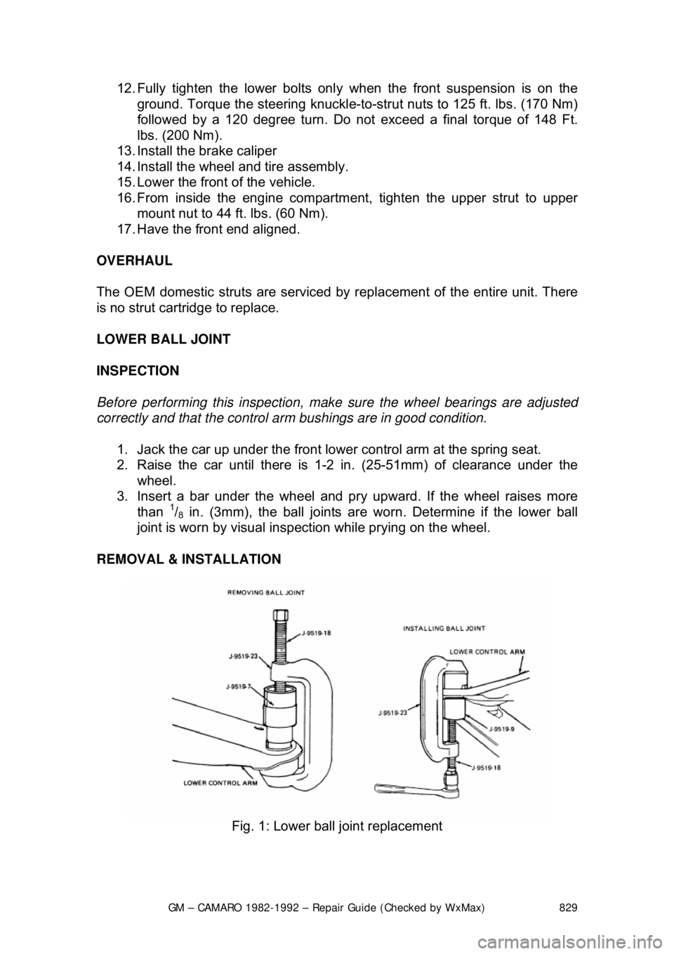
LOWER BALL JOINT
INSPECTION
Before performing this inspection, make sure the wheel bearings are adjusted
correctly and that the control arm bushings are in good condition.
1. Jack the car up under the front lower control arm at the spring seat.
2. Raise the car until t here is 1-2 in. (25-51mm) of clearance under the
wheel.
3. Insert a bar under the wheel and pr y upward. If the wheel raises more
than
1/8 in. (3mm), the ball joints are worn. Determine if the lower ball
joint is worn by visual inspec tion while prying on the wheel.
REMOVAL & INSTALLATION
Fig. 1: Lower ball joint replacement
Page 832 of 875

GM – CAMARO 1982-1992 – Repair Guide (Checked by WxMax) 832
6. Hold the stabilizer shaft approximat
ely 55mm from the bottom of the side
rail and torque the bracket bolts to 37 ft. lbs. (50 Nm).
7. Install the bolt, nut, grommets, spacer and retainers.
8. Lower the car.
LOWER CONTROL ARM
REMOVAL & INSTALLATION 1. Raise the car and safely support on jackstands.
2. Remove the wheel and tire.
3. Remove the stabilizer link and bush ings at the lower control arm.
4. Remove the pivot bolt nuts. DO NOT re move the pivot bolts at this time.
5. Install tool J-23028 or equivalent adapter to the jack and place into
position with tool J-23028 or equival ent adapter supporting bushings.
6. Install the jackstand under the outsi de frame rail on the opposite side of
the vehicle.
7. Raise tool J-23028 or equivalent adapter enough to remove both pivot
bolts.
8. Lower tool J-23028 or equivalent adapter.
9. Remove the spring and insulato r tape insulator to the spring.
10. Remove the ball joint from the knuckle.
11. To install, reverse the removal procedure.
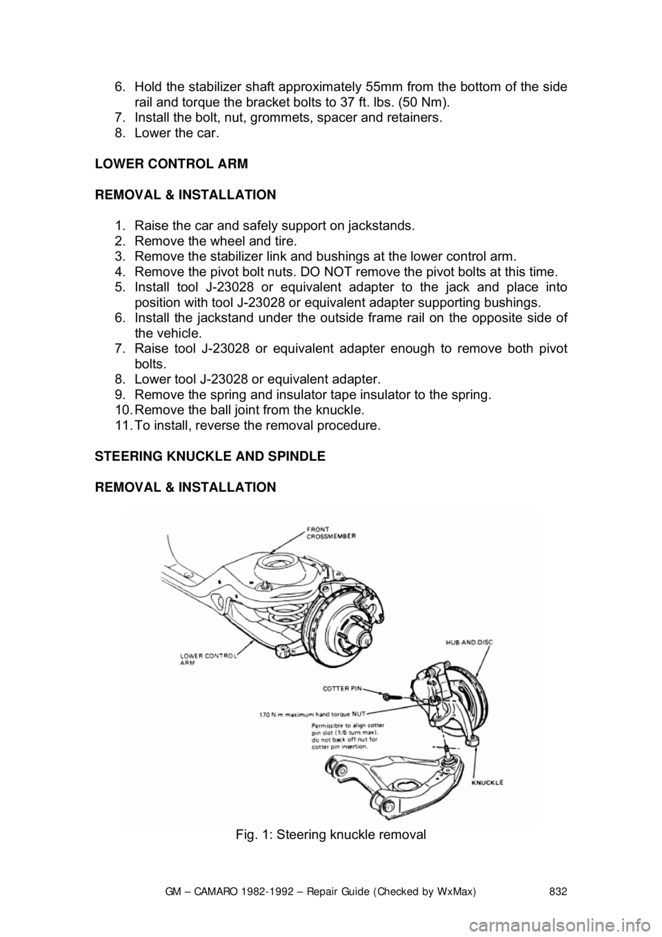
STEERING KNUCKLE AND SPINDLE
REMOVAL & INSTALLATION
Fig. 1: Steering knuckle removal
Page 845 of 875

GM – CAMARO 1982-1992 – Repair Guide (Checked by WxMax) 845
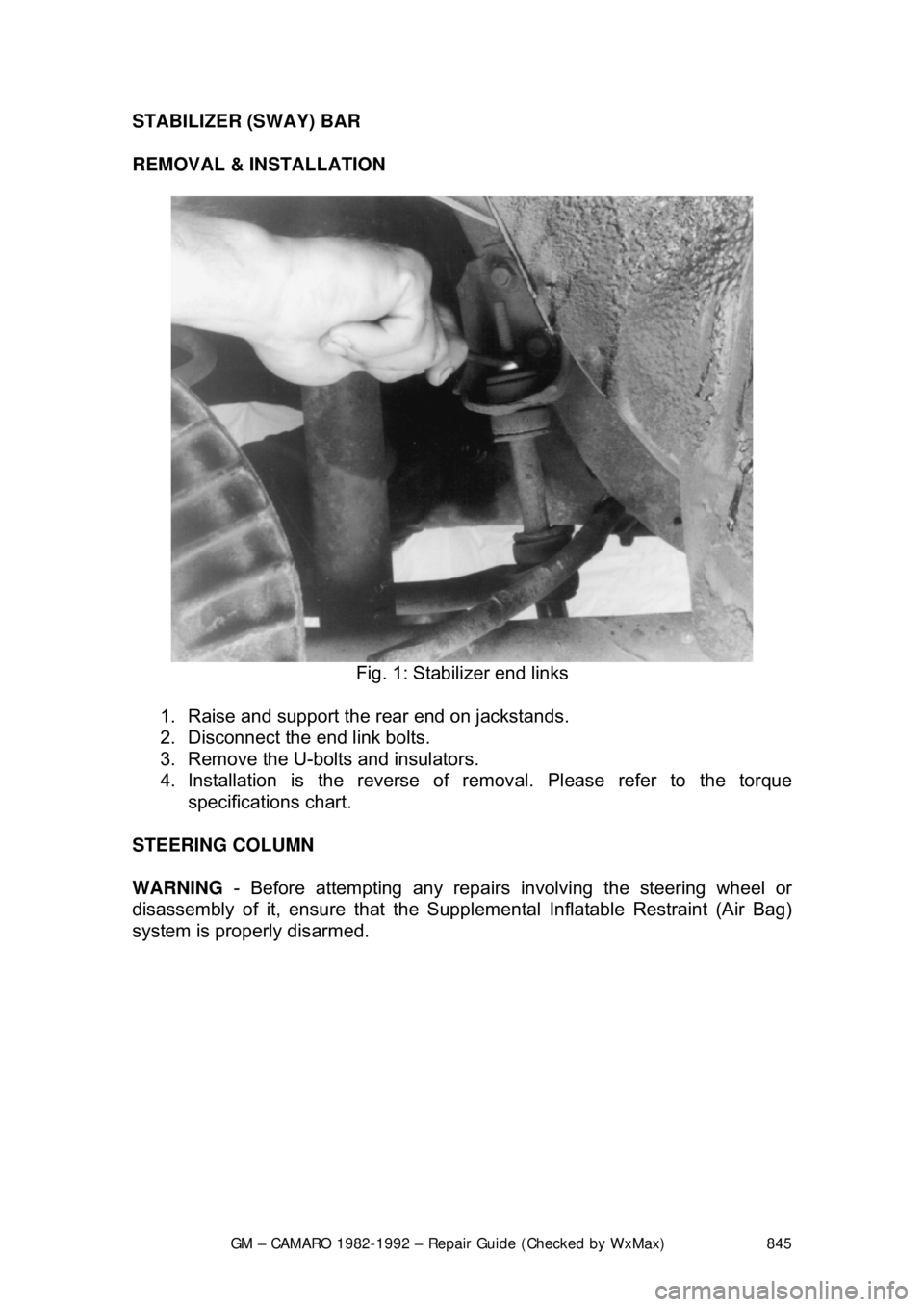
STABILIZER (SWAY) BAR
REMOVAL & INSTALLATION
Fig. 1: Stabilizer end links
1. Raise and support the rear end on jackstands.
2. Disconnect the end link bolts.
3. Remove the U-bolts and insulators.
4. Installation is the reverse of re moval. Please refer to the torque
specifications chart.
STEERING COLUMN
WARNING - Before attempting any repairs involving the steering wheel or
disassembly of it, ensure that the Supple mental Inflatable Restraint (Air Bag)
system is properly disarmed.