1982 CHEVROLET CAMARO crankcase
[x] Cancel search: crankcasePage 390 of 875

GM – CAMARO 1982-1992 – Repair Guide (Checked by WxMax) 390
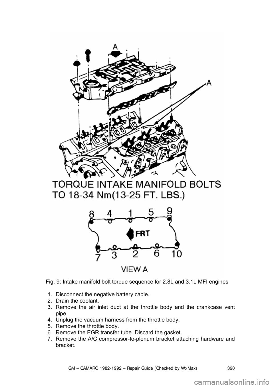
Fig. 9: Intake manifold bolt tor que sequence for 2.8L and 3.1L MFI engines
1. Disconnect the negative battery cable.
2. Drain the coolant.
3. Remove the air inlet duct at t he throttle body and the crankcase vent
pipe.
4. Unplug the vacuum harness from the throttle body.
5. Remove the throttle body.
6. Remove the EGR transfer tube. Discard the gasket.
7. Remove the A/C compressor-to-plenum bracket attaching hardware and
bracket.
Page 417 of 875

GM – CAMARO 1982-1992 – Repair Guide (Checked by WxMax) 417
16. Fill the cooling syst
em with the proper type and amount of coolant.
Connect the negative battery cable.
17. Raise and support the vehicle safely . Install a new oil filter, lower the
vehicle. Fill the crankcase with the proper type and quantity of engine oil.
18. Start the engine, check for lea ks and check the ignition timing.
OIL PAN
REMOVAL & INSTALLATION
CAUTION - The EPA warns that prolonged contact with used engine oil may
cause a number of skin disorders, incl uding cancer! You should make every
effort to minimize your exposure to used engine oil. Pr otective gloves should be
worn when changing the oil. Wash y our hands and any other exposed skin
areas as soon as possible after exposure to used engine oil. Soap and water, or
waterless hand cleaner should be used.
EXCEPT 2.5L ENGINE
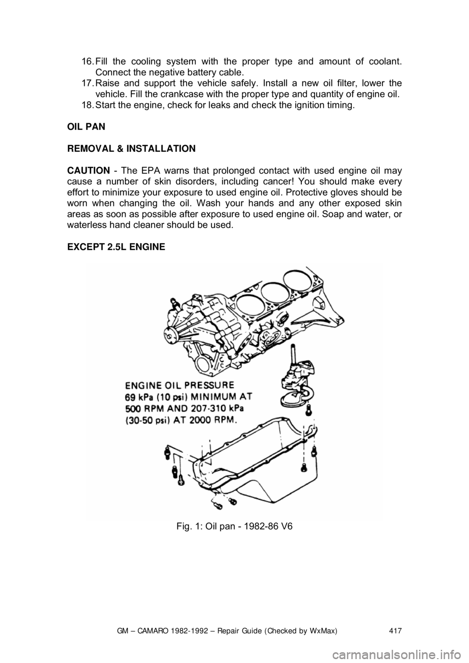
Fig. 1: Oil pan - 1982-86 V6
Page 425 of 875

GM – CAMARO 1982-1992 – Repair Guide (Checked by WxMax) 425
1. Drain and remove the oil pan.
CAUTION - The EPA warns that prolonged contact with used engine oil may
cause a number of skin disorders, incl uding cancer! You should make every
effort to minimize your exposure to used engine oil. Pr otective gloves should be
worn when changing the oil. Wash y our hands and any other exposed skin
areas as soon as possible after exposure to used engine oil. Soap and water, or
waterless hand cleaner should be used.
2. Remove the oil pump-to-rear main bearing cap bolt. Remove the pump
and the extension shaft.
3. Remove the cotter pin, spring and pressure regulator valve.
Place your thumb over the pressure r egulators bore before removing the cotter
pin, as the spring is under pressure.
To install: 4. Assemble pump and extension shaft to rear main bearing cap, aligning
slot on top end of extension shaft with drive tang on lower end of
distributor driveshaft.
When assembling the driveshaft extensi on to the driveshaft, the end of the
extension nearest the washers must be inserted into the driveshaft.
5. Insert the driveshaft extension through the opening in the main bearing
cap and block until the shaft mates in to the distributor drive gear.
6. Install the pump onto t he rear main bearing cap and install the attaching
bolts. Torque the bolts to specifications:
• L4 engines: 22 ft lbs. (30 Nm)
• V6 engines: 25-35 ft lbs. (35-47 Nm)
• V8 engines: 65 ft lbs. (88 Nm)
7. Install the oil pan and fill t he crankcase with engine oil.
CRANKSHAFT DAMPER
REMOVAL & INSTALLATION
Page 443 of 875

GM – CAMARO 1982-1992 – Repair Guide (Checked by WxMax) 443
Ensure that oil holes are properly al
igned. Replace camshaft rear plug, and
stake it into position to aid retention.
INSPECTION
CAMSHAFT LOBE LIFT
Check the lift of each lobe in consecutiv e order and make a note of the reading.
1. Remove the fresh air inlet tube a nd the air cleaner. Remove the heater
hose and crankcase ventilation hoses. Remove valve rocker arm
cover(s).
2. Remove the rocker arm stud nut or fulcrum bolts, fulcrum seat and rocker
arm.
3. Make sure the pushrod is in the valve tappet socket. Install a dial indicator so that the actuating poin t of the indicator is in the pushrod
socket (or the indicator ball socket adapter tool is on the end of the
pushrod) and in the same plane as the pushrod movement.
4. Disable the ignition and fuel systems.
5. Install a remote starter switch. Crank the engine with the ignition and fuel
system disabled. Turn the crankshaft ov er until the tappet is on the base
circle of the camshaft lobe. At this position, the pushrod will be in its
lowest position.
6. Zero the dial indicator. Continue to rotate the crankshaft slowly until the
pushrod is in the fully raised position.
7. Compare the total lift recorded on the dial indicator with the specification
shown on the Camshaft Specification chart.
To check the accuracy of the original in dicator reading, continue to rotate the
crankshaft until the indicator reads zero. If the lift on any lobe is below specified
wear limits listed, the ca mshaft and the valve tappet operating on the worn
lobe(s) must be replaced.
8. Install the rocker arm, fulcrum seat and stud nut or fulcrum bolts. Adjust
the valves, if required (r efer to the valves procedure in this section).
9. Install the valve rocker arm cover(s) and the air cleaner.
CAMSHAFT END PLAY
On all gasoline V8 engi nes, prying against the aluminum-nylon camshaft
sprocket, with the valve train load on t he camshaft, can break or damage the
sprocket. Therefore, the rocker arm adj usting nuts must be backed off, or the
rocker arm and shaft assembly must be loosened sufficiently to free the
camshaft. After checking the camshaft e nd play, check the valve clearance.
Adjust if required (refer to procedure in this section).
1. Push the camshaft toward the rear of the engine. Install a dial indicator or
equivalent so that the indicator point is on the camshaft sprocket
attaching screw.
Page 453 of 875

GM – CAMARO 1982-1992 – Repair Guide (Checked by WxMax) 453
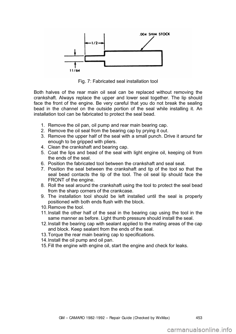
Fig. 7: Fabricated s eal installation tool
Both halves of the rear main oil s eal can be replaced without removing the
crankshaft. Always replace the upper and lower seal together. The lip should
face the front of the engine. Be very ca reful that you do not break the sealing
bead in the channel on the out side portion of the seal while installing it. An
installation tool can be fabricat ed to protect the seal bead.
1. Remove the oil pan, oil pump and rear main bearing cap.
2. Remove the oil seal from the bearing cap by prying it out.
3. Remove the upper half of the seal wit h a small punch. Drive it around far
enough to be gripped with pliers.
4. Clean the crankshaft and bearing cap.
5. Coat the lips and bead of the seal with light engine oil, keeping oil from
the ends of the seal.
6. Position the fabricated tool bet ween the crankshaft and seal seat.
7. Position the seal between the cranks haft and tip of the tool so that the
seal bead contacts the ti p of the tool. The oil seal lip should face the
FRONT of the engine.
8. Roll the seal around the crankshaft us ing the tool to protect the seal bead
from the sharp corner s of the crankcase.
9. The installation tool should be le ft installed until the seal is properly
positioned with both ends fl ush with the block.
10. Remove the tool.
11. Install the other half of the seal in the bearing cap using the tool in the
same manner as before. Light thumb pressure should install the seal.
12. Install the bearing cap with sealant applied to the mating areas of the cap
and block. Keep sealant from the ends of the seal.
13. Torque the rear main bear ing cap to specifications.
14. Install the oil pump and oil pan.
15. Fill the engine with engine oil, st art the engine and check for leaks.
Page 466 of 875

GM – CAMARO 1982-1992 – Repair Guide (Checked by WxMax) 466
wear. Worn piston rings, scored or wo
rn cylinder bores, blown head gaskets,
sticking or burnt valves, and worn valve seats are all possible culprits. A check
of each cylinder's compression will help locate the problem.
A screw-in type compression gauge is more accurate than the type you simply
hold against the spark plug hole. Although it takes slightly longer to use, it's
worth the effort to obtain a more accurate reading.
1. Make sure that the proper amount and viscosity of engine oil is in the
crankcase, then ensure the battery is fully charged.
2. Warm-up the engine to normal operat ing temperature, then shut the
engine OFF.
3. Disable the ignition system.
4. Label and disconnect all of the spark plug wires from the plugs.
5. Thoroughly clean the cylinder h ead area around the spark plug ports,
then remove the spark plugs.
6. Set the throttle plate to the fully open (wide-open throttle) position. You
can block the accelerator linkage open for this, or you can have an
assistant fully depress the accelerator pedal.
Fig. 1: A screw-in type compression gauge is more accurate and easier to use
without an assistant
7. Install a screw-in type compression gauge into the No. 1 spark plug hole
until the fitting is snug.
WARNING - Be careful not to crossthread the spark plug hole.
Page 468 of 875

GM – CAMARO 1982-1992 – Repair Guide (Checked by WxMax) 468
7. Compare your hot oil pressure reading
to that given in the chart. If the
reading is low, check the cold pressu re reading against the chart. If the
cold pressure is well above the spec ification, and the hot reading was
lower than the specificat ion, you may have the wr ong viscosity oil in the
engine. Change the oil, making sure to use the proper grade and
quantity, then repeat the test.
Low oil pressure readings could be attributed to internal component wear, pump
related problems, a low oil leve l, or oil viscosity that is too low. High oil pressure
readings could be caused by an overfilled crankcase, too high of an oil viscosity
or a faulty pressure relief valve.
BUY OR REBUILD?
Now that you have determined that your engine is worn out, you must make
some decisions. The question of whether or not an engine is worth rebuilding is
largely a subjective matter and one of per sonal worth. Is the engine a popular
one, or is it an obsolete model? Are parts available? Will it get acceptable gas
mileage once it is rebuilt? Is the car it's being put into worth keeping? Would it
be less expensive to buy a new engine, have your engine rebuilt by a pro,
rebuild it yourself or buy a used engine from a salvage yard? Or would it be
simpler and less expensive to buy another car? If you have considered all these
matters and more, and have still decided to r ebuild the engine, then it is time to
decide how you will rebuild it.
The editors of this information feel that most engine machining should be
performed by a professional machine shop. Don't think of it as wasting money,
rather, as an assurance that the job has been done right the first time. There
are many expensive and spec ialized tools required to perform such tasks as
boring and honing an engine block or having a valve job done on a cylinder
head. Even inspecting the parts requires expensive micrometers and gauges to
properly measure wear and clearances. Al so, a machine shop can deliver to
you clean, and ready to assemble parts, saving you time and aggravation. Your
maximum savings will come from perf orming the removal, disassembly,
assembly and installation of the engine and purchasing or renting only the tools
required to perform the above tasks. Depending on the particular
circumstances, you may save 40 to 60 perc ent of the cost doing these yourself.
A complete rebuild or overhaul of an engine involves replacing all of the moving
parts (pistons, rods, crankshaft, camsha ft, etc.) with new ones and machining
the non-moving wearing surfaces of t he block and heads. Unfortunately, this
may not be cost effective. For instanc e, your crankshaft may have been
damaged or worn, but it can be machined undersize for a minimal fee.
So, as you can see, you can replace ev erything inside the engine, but, it is
wiser to replace only those parts whic h are really needed, and, if possible,
repair the more expensive ones. Later in this section, we will break the engine
down into its two main components: t he cylinder head and the engine block. We
will discuss each component, and the re commended parts to replace during a
rebuild on each.
Page 512 of 875

GM – CAMARO 1982-1992 – Repair Guide (Checked by WxMax) 512
5. Make sure the ring gaps are pr
operly spaced around the circumference
of the piston. Fit a piston ring co mpressor around the piston and slide the
piston and connecting rod assembly do wn into the cylinder bore, pushing
it in with the wooden hammer handle. Pu sh the piston down until it is only
slightly below the top of the cylinder bore. Guide the connecting rod onto
the crankshaft bearing journal carefully, to avoid damaging the
crankshaft.
6. Check the bearing clearance of all the rod bearings, fitting them to the
crankshaft bearing journals. Follow the procedure in the crankshaft
installation above.
7. After the bearings have been fitted, apply a light coating of assembly oil
to the journals and bearings.
8. Turn the crankshaft until the appropria te bearing journal is at the bottom
of its stroke, then push the piston a ssembly all the way down until the
connecting rod bearing seat s on the crankshaft journal. Be careful not to
allow the bearing cap screws to stri ke the crankshaft bearing journals
and damage them.
9. After the piston and connecting rod assemblies have been installed, check the connecting rod side clearance on each crankshaft journal.
10. Prime and install t he oil pump and the oil pump intake tube.
CAMSHAFT, LIFTERS AND TIMING ASSEMBLY 1. Install the camshaft.
2. Install the lifters/followers into their bores.
3. Install the timing gears/chain assembly.
CYLINDER HEAD(S) 1. Install the cylinder head(s) using new gaskets.
2. Assemble the rest of the valve tr ain (pushrods and rocker arms and/or
shafts).
ENGINE COVERS AND COMPONENTS
Install the timing cover(s) and oil pan. Re fer to your notes and drawings made
prior to disassembly and install all of the components that were removed. Install
the engine into the vehicle.
ENGINE START-UP AND BREAK-IN
STARTING THE ENGINE
Now that the engine is inst alled and every wire and hose is properly connected,
go back and double check that all cool ant and vacuum hoses are connected.
Check that you oil drain plug is instal led and properly tightened. If not already
done, install a new oil filt er onto the engine. Fill the crankcase with the proper
amount and grade of engine oil. Fill the cooling system with a 50/50 mixture of
coolant/water.