Page 27 of 875
GM – CAMARO 1982-1992 – Repair Guide (Checked by WxMax) 27
19. Install the instrument panel sound insulators.
20. Install the inst
rument panel pad.
21. Install the daytime running light sensor electrical connector, if equipped.
22. Install the screws attaching the in strument panel pad to the instrument
panel.
23. Install the center console.
24. Properly arm the SIR air bag syste m, if equipped. Disconnect the negative
battery cable.
DOOR PANELS
REMOVAL & INSTALLATION
Fig. 1: Armrest and pull handle
Page 29 of 875

GM – CAMARO 1982-1992 – Repair Guide (Checked by WxMax) 29
attachment hole in the trim panel, rotate the retainer until the flange is
engaged fully.
12. Connect all electrical components where present.
13. To install the door trim panel, locate the top of the assembly over the upper
flange of the door inner panel, inserting the door handle through the handle
slot in the panel and press down on the trim panel to engage the upper
retaining clips.
14. Position the trim panel to the door inner panel so the trim retainers are
aligned with the attaching holes in t he panel and tap the retainers into the
holes with the palm of hand or a clean rubber mallet.
15. Install the screws used to hold the armrest to the inner panel.
16. Install the remote control handle bezel screws.
17. On models with power door lock contro ls located in the door trim panel,
connect the wire harnesses at the switch assemblies.
18. On models with remote control mirror assemblies, install the control to the
plate. Install the control plate to the bezel on the trim pad.
19. Install the handle assemb ly and install the screws inserted through the door
armrest.
20. Install the door inside locking rod knob.
21. Install all the door inside handles.
HEADLINER
REMOVAL & INSTALLATION
Fig. 1: Headliner installation
1. Disconnect the negative battery cable.
2. Remove the dome lamp and sunshade.
3. Remove the coat hooks and seat bel t escutcheon, by unsnapping from the
headliner.
4. Remove the rear window opening molding.
Page 33 of 875
GM – CAMARO 1982-1992 – Repair Guide (Checked by WxMax) 33
Fig. 2: Door lock actuator
1. Disconnect the negative battery c able. Remove the door panel.
2. Raise the window fully. Disconnect t he electrical connector from the
actuator.
3. Drive the rivet cent er pins out using a
1/8 in. (3mm) punch and hammer, then
using a 1/4 in. (6mm) drill bit, remove the rivet head.
4. Remove the actuator rod and remove the door lock actuator.
5. Installation is the revers e of the removal procedure.
Page 34 of 875

GM – CAMARO 1982-1992 – Repair Guide (Checked by WxMax) 34
REAR LIFTGATE PULL-DOWN UNIT
REMOVAL & INSTALLATION
Fig. 1: Pull-down lock unit
1. Open the rear hatch. Disconnec t the negative battery cable.
2. Remove the rear trim panel. Disconnec t the electrical connector and remove
the attaching screws.
3. Disconnect the unit lock cable co nnection from the lock cylinder.
4. Remove the unit.
5. Installation is the reverse of the re moval procedure. Torque the screws to 18
ft. lbs. (24 Nm).
ADJUSTMENT
Adjust the unit as necessary fo r proper lock striker engagement.
DOOR WINDOW
REMOVAL & INSTALLATION
1. Remove the door trim panel and the inner panel water deflector.
2. Raise the window to the half-up position.
3. Punch out the center pins of the gl ass to sash channel attaching rivets.
4. Remove the rear guide channel through the rear access hole.
5. Remove the up stop.
6. Using a
1/4 in. (6mm) drill bit, drill out the atta ching rivets on sash channel.
7. Raise the glass to remove from the sash channel and remove the glass from
the door.
Page 69 of 875
GM – CAMARO 1982-1992 – Repair Guide (Checked by WxMax) 69
Fig. 3: Single (A) and double (B) flares
Fig. 4: ISO flare
• REMOVAL & INSTALLATION
1. Disconnect the negative battery cable.
2. Raise and safely support the vehicle on jackstands.
Page 73 of 875

GM – CAMARO 1982-1992 – Repair Guide (Checked by WxMax) 73
To install:
9. Install the new line or hose, starti
ng with the end farthest from the master
cylinder. Connect the other end, then confirm that both fittings are correctly
threaded and turn smoothly using finger pressure. Make sure the new line
will not rub against any ot her part. Brake lines must be at least 1/2 in.
(13mm) from the steering column and other moving parts. Any protective
shielding or insulators must be rein stalled in the original location.
WARNING - Make sure the hose is NO T kinked or touching any part of the
frame or suspension after installation. These conditions may cause the hose to
fail prematurely.
10. Using two wrenches as bef ore, tighten each fitting.
11. Install any retaining clips or brackets on the lines.
12. If removed, install the wheel and tire assemblies, then carefully lower the
vehicle to the ground.
13. Refill the brake master cylinder re servoir with clean, fresh brake fluid,
meeting DOT 3 specifications. Pr operly bleed the brake system.
14. Connect the negative battery cable.
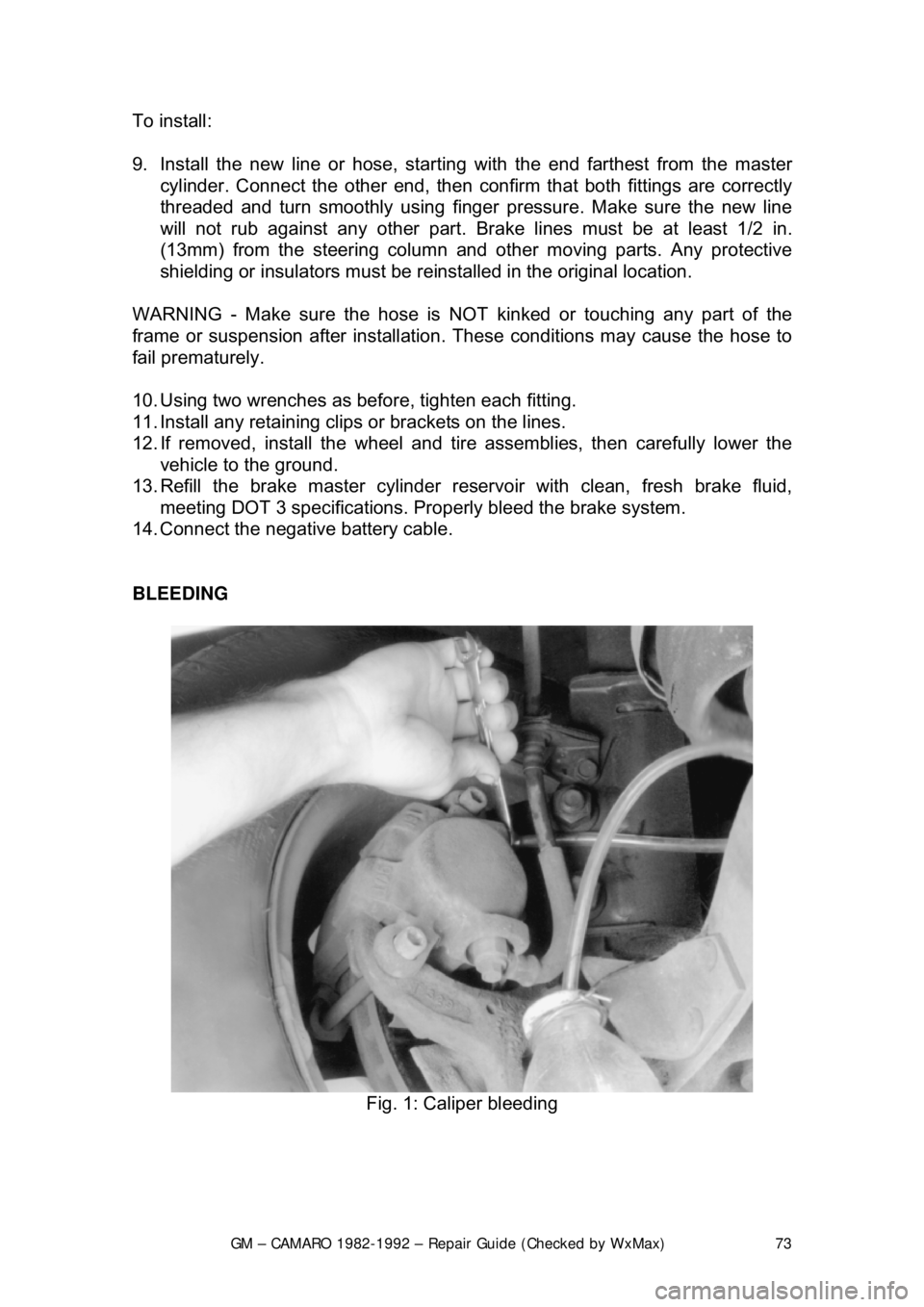
BLEEDING
Fig. 1: Caliper bleeding
Page 126 of 875

GM – CAMARO 1982-1992 – Repair Guide (Checked by WxMax) 126
CHASSIS ELECTRICAL
UNDERSTANDING AND TROUBLESHOOTING ELECTRICAL SYSTEMS
BASIC ELECTRICAL THEORY
For any 12 volt, negative ground, electrical system to operate, the electricity
must travel in a complete circuit. This simply means that current (power) from
the positive (+) terminal of the battery must eventually return to the negative (—
) terminal of the battery. Along the way, this current will travel through wires,
fuses, switches and components. If, for any reason, the flow of current through
the circuit is interrupted, the component f ed by that circuit will cease to function
properly.
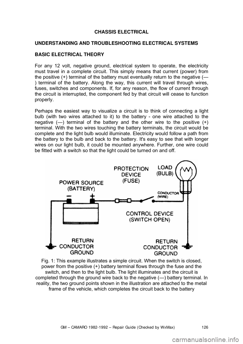
Perhaps the easiest way to visualize a circ uit is to think of connecting a light
bulb (with two wires attac hed to it) to the battery - one wire attached to the
negative (—) terminal of the battery and the other wire to the positive (+)
terminal. With the two wires touching the battery terminals, the circuit would be
complete and the light bulb would illuminat e. Electricity would follow a path from
the battery to the bulb and back to the bat tery. It's easy to see that with longer
wires on our light bulb, it could be mounted anywhere. Further, one wire could
be fitted with a switch so that t he light could be turned on and off.
Fig. 1: This example illu strates a simple circuit. Wh en the switch is closed,
power from the positive (+) battery te rminal flows through the fuse and the
switch, and then to the light bulb. The light illuminates and the circuit is
completed through the ground wire back to the negative (—) battery terminal. In
reality, the two ground point s shown in the illustration are attached to the metal
frame of the vehicle, which comple tes the circuit back to the battery
Page 127 of 875

GM – CAMARO 1982-1992 – Repair Guide (Checked by WxMax) 127
The normal automotive circuit differs from
this simple example in two ways.
First, instead of having a return wire from the bulb to the battery, the current
travels through the frame of the vehicle. Since the negative (—) battery cable is
attached to the frame (made of electrically conductive metal), the frame of the
vehicle can serve as a ground wire to complete the circuit. Secondly, mo\
st
automotive circuits contain multiple components which receive power from a
single circuit. This lessens the amount of wire needed to power components on
the vehicle.
HOW DOES ELECTRICITY WORK: THE WATER ANALOGY
Electricity is the flow of electrons - t he subatomic particles that constitute the
outer shell of an atom. Elec trons spin in an orbit around the center core of an
atom. The center core is comprised of protons (positive charge) and neutrons
(neutral charge). Electrons have a negativ e charge and balance out the positive
charge of the protons. When an outside forc e causes the number of electrons to
unbalance the charge of the protons, the electrons will split off the atom and
look for another atom to balance out. If th is imbalance is kept up, electrons will
continue to move and an elec trical flow will exist.
Many people have been taught electrical th eory using an analogy with water. In
a comparison with water flowing through a pipe, the electrons would be the
water and the wire is the pipe.
The flow of electricity can be measur ed much like the flow of water through a
pipe. The unit of measur ement used is amperes, frequently abbreviated as
amps (a). You can compare amperage to th e volume of water flowing through a
pipe. When connected to a circuit, an ammeter will measure the actual amount
of current flowing through the circuit. W hen relatively few electrons flow through
a circuit, the amperage is low. When many electrons flow, the amperage is high.
Water pressure is measured in units su ch as pounds per square inch (psi); The
electrical pressure is m easured in units called volts (v). When a voltmeter is
connected to a circuit, it is meas uring the electrical pressure.
The actual flow of electricity depends not only on voltage and amperage, but
also on the resistance of the circuit. T he higher the resistance, the higher the
force necessary to push the current through the circuit. The standard unit for
measuring resistance is an ohm. Resistance in a circuit varies depending on the
amount and type of components used in t he circuit. The main factors which
determine resistance are:
• Material - some materials have more resistance than others. Those with
high resistance are said to be insulato rs. Rubber materials (or rubber-like
plastics) are some of the most common insulators used in vehicles as
they have a very high resistance to electricity. Very low resistance
materials are said to be conductors. Copper wire is among the best
conductors. Silver is actually a super ior conductor to copper and is used
in some relay contacts, but its hi gh cost prohibits its use as common
wiring. Most automotive wir ing is made of copper.