1980 CHEVROLET CITATION instrument cluster
[x] Cancel search: instrument clusterPage 28 of 95

Downloaded from www.Manualslib.com manuals search engine • Holding. vehicle on an upgrade with the accelerator pedal. (Use the regular
brakes to hold car on an uphill grade.)
Column Shift Lever
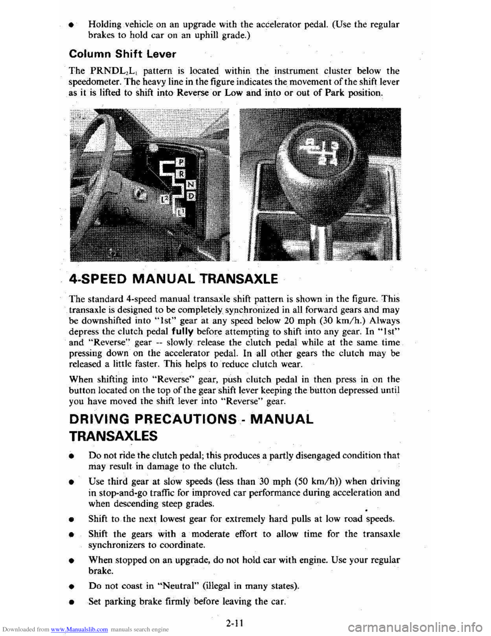
The PRNDL1L1 pattern is located within the instrument cluster below the
speedometer.
The heavy line in the figure indicates the movement of the shift lever
as it
is lifted to shift into Reverse or Low and into or out of Park position.
4·SPEED MANUAL TRANSAXLE
The standard 4-speed manual transaxle shift pattern is shown in the figure. This
transaxle
is designed to be cOinpletely sypchronized in all forward gears and may
be downshifted into "1st" gear at any speed below 20 mph (30 km/h.) Always
depress the clutch pedal
fully before attempting to shift into any gear. In "1st"
and "Reverse " gear --slowly release the clutch pedal while at the same time
pressing down· on the accelerator pedal. In all other gears the clutch may be
released a little faster. This helps to reduce clutch wear.
When shifting into
"Reverse" gear, push clutch pedal in then press in on the
button located on the top of the gearshift lever keeping thehutton depressed until
you have moved the shift
lever into "Reverse" gear.
DRIVING PRECAUTIONS· MANUAL
TRANSAXLES
• Do not ride the dutch pedal; this produces a partly disengaged condition that may result in damage to the clutch.
• Use third gear at slow speeds (less than 30 mph (50 km/h)) when driving
in stop-and-go traffic for improved
car performance during acceleration and
when descending steep grades.
• Shift to the next lowest gear for extremely hard pulls at low road speeds.
• Shift the gears with a moderate effort to allow time for the transaxle
synchronizers to coordinate.
• When stopped on an upgrade, do not hold car with engine. Use your regular
brake.
• Do not coast in "Neutral" (i1legal in many states).
• Set parking brake firmly before leaving the car.
Page 32 of 95

Downloaded from www.Manualslib.com manuals search engine • Never drive-the vehicle _with the parking brake set as this -may overheat the
reaf brakes reducing their effectiveness and causing excessive wear or damage,
DISC BRAKE WEAR INDICATORS
Front disc brakes have built-in wear indicators that are designed to make a
high-pitched
squealing or cricket-like warning sound when the brake linings are
worn 10 where -new linings are needed. The sound will come and go, or be heard
all the time
when the wheels are rolling, and when the brake pedal is pu~hed down
firmly . Expensive damage can result
if linings are not replaced when needed.
See also the brake checks listed in the Maintenance Schedule folder.
CLUTCH .PEDAL
On models equiPPed with a manual transaxle, a clutch pedal is used to engage
or disengage the clutch, thereby connecting
or disconnecting the engine from the
transaxle and drive1ine to the front wheels. -When the pedal is fully extended the
clutch
is engaged, driving the transaxle arid the front wheels.
INSTRUMENT PANEL P.ND CONTROLS
INSTRUMENTS
The instruments, gages and indicator lights conveniently grouped in the
instrument cluster are des igned to
tell you at a glance many important things about
_the perfonnance of your vehicle _, _ The following information will enable you to
more quickly -understand and properly it';:rerpretthese instruments.
Speedometer
The speedometer chand ·indicatt:5 vehicle speed in miles per hour and kilometers
per hour.
Odometer
The group of six figures . in the speedometer lower center section indicates the
accumulated mileage.
Fuel Gage
The fuel gagewiH register the_APPROXIMATE fuel level in the tank, when the
ignition
is in the RUN position.
When the gage registers
EMPTY, some fuel is still available as a reserve. When
the gage registers
FULL. some additional" fuel can"still be added to the tank. The
following conditiqns may be considered normal:
• Gas station _pump may shut off before fuel gage indicates FULL. •
•
Amount of gasoline required for fill-up may not exactly correspond to gage.
• Needle may not move away from FULL until some time after fill·up.
• Needle may !Dove during turns. stops and-accelerations.
When the ignition switch
is turned to the OFF position, the needle will not
necessarily
retiJrn · all the way to the EMPTY mark.
2-15
Page 34 of 95

Downloaded from www.Manualslib.com manuals search engine Oil/Choke Indicator Light
This light will c0!TIe on to provide a "bulb check", w hen the igni tion is turned on, but sh Qu19 go out after the _ engine is started. If tight fails to
come on wit h ignitio~ turned on, it could indicate a burned out bulb , a
defective electric choke hea ter circuit (on L4 and V6 engines), or a blown
instrument lamp fuse. Have system repaired if light does not come on d min g ch eck .
Occa sionally. this light may flicker momentarily while the engine is running. Should this occur, CHECK EN GINE OIL LEVEL as outlined in Section 5,
"Checking Oil Level." If the light comes on continuously, pull over toa safe place and STOP THE ENGINE until the source of trouble can be loca ted and corrected.
The source of tro uble could be any of the following:
• Loss of engine oil press ure (cbec k eng ine oil level).
• Blown choke heater fuse.
• Loss. of electric choke heate r voltage.
Continuing to run the engine with an illuminated oil pressure light can cause
serious engine damage or unusu ally high exhaust system temperature which can
r esult in serio us damage to the
vehicle. Pull over to a safe place and STOP THE
VEHICLE IMMEDIATELY AND SHUT OFF ENGINE. If the light flashe s
momentarily , ch
eck engine oil leve l as outlined in Sectio n 5 of thi s manu al
Choke Warning Indicator Light
On some vehicles equipped with the optiona l oil pressure gage, an amber choke
warning indicator light replaces the red oil pressure indicator light in the
instrument cluste
r. If this light comes on, indicating loss of electric choke heater
volta
ge, have your authoriz ed Dea ler .locate and correct th e tro uble as soon as
p ossib l
e.
Generator Indicator Light The red ligh t GEN will go on when the ignition key is in the "run" _posit ion, but
before the engi ne
is started. After the engine s tarts, the light should 'go out and
r e m ain out .
If th e light remains on when en gine is running , have your Authorized
D eale r loca te and correct the troubl e as soo n as possibl
e.
Engine Temperature .Indicator Light This indicator light is provided in th e instrument cluster to quickly warn of an
overh eated en gi ne. With the igniti on switch in the START position, the red
TEMP indicator (hot light) will light to let you know that it is operati ng prope rly.
When the engi ne is started ;-th e re d light will go out imm ediate ly. It wilUight up
a t n o other time unleSS for some reason the engine reaches a dangerously high ope ra tin g temperature . 1f the light comes on during extreme driving condition s,
such as an exte nded idle, see "E ngine Cooling
System" on page 3-3. Glance at
th e instrument cluster frequently as you drive to see if this
ligh t is on.
Brake System Warning Light
The regular braking system is a dual system designed so that one part will provide
some braking action if there is a loss of hydraulic pressure in the other part of
the system. The system has a "Brake" warning light loca ted in the instrum ent
pane\.
• To serve as a reminder , the "Bra ke" lig ht is designed to come on while the
park ing brake is se t and the ignition key
is on.
• The light is also designed to come on briefly during engine starting so you
can chec k that the bulb is okay.
• Have the system repaired if the light does not come on during engine starting
o r when the parking brake
is set. 2-17
Page 37 of 95

Downloaded from www.Manualslib.com manuals search engine When the parking lamps or headlamps are to be operated with the key in the OFF position. the reminder buzzer can be shut off by turning the light switch knob
until the instrument cluster lights are not on.
Electric Clock
Reset the clock, . if your vehicle is so equipjled. by pulling out the knob and turning the hands clockwise if slow, counterclockwise if fast. This win, if the clock error
is five minutes or more, automatically compensate for time' gain or lag. Several
reseuings, several days apart. may be needed to properly adjust the c10ck
mechanism.
Cigarette Lighter
The optional cigarette lighter is located "in-the ash tray. To operate,- -push it in.
When it becomes heated, it automatically pops out ready for use. ,
VENTILATION. SYSTEM
Your Citation has a power verttiI3:tion system' that provides ventilation comfort by forcing air out through valves in the rear body lock. pillars. You can get a steady
flow of outside air into the car when the heater ot air conditioning blower is turned
on, On cars without air conditioning, you can get a "'ram" fresh .air supply while
the car is moving, with the heater blower· turiled off.
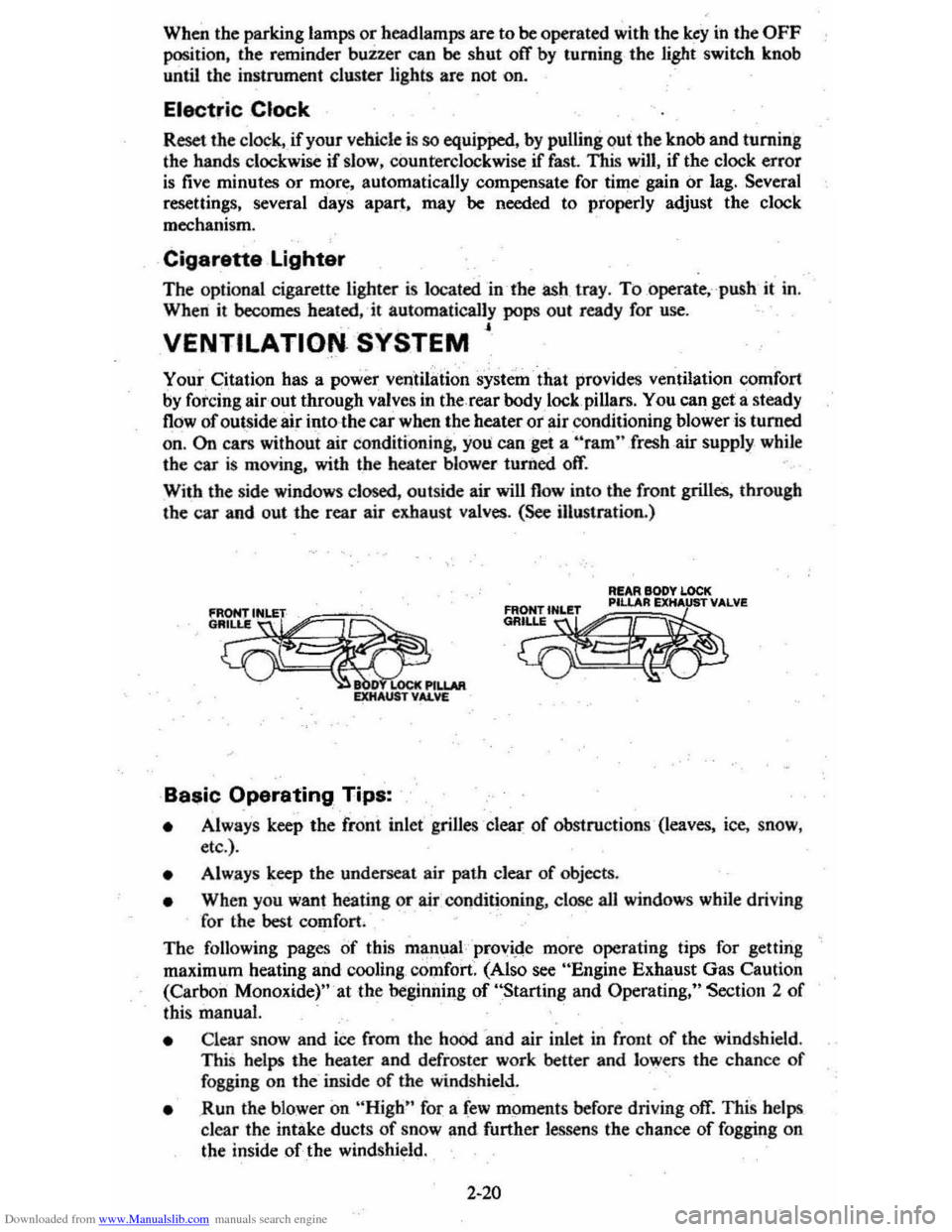
With the side windows closed, outside air will flow into the front grilles. through the car and out the rear air exhaust valves. (See illustration.)
fRONrlNLET
G~.
LOCt
R!AR BODY LOCK
~~~m
• Always keep the fro'nt inlet' grilles clear of obstructions ' (leaves, ice, snow,
etc .).
• Alw.ays keep the underseat ai r path clear of objects.
• When you want heating or air COllditioning, close aU windows while driving
for
the best comfort.
The following pages of this mlin,ual provi.de more operating tips for gettina
maximum heating and cooling , comfort. (Also see "Engine Exhaust Gas Caution
(Carbon Monoxide)" 'at the begiiuling of "Starting and Operating," Section 2 of
this manual.
• Clear snow and ice from the hood 'and air inlet in front of the windshield . This helps the heater and defroster work better and lowers the chance of fogging on the' inside of the windshield.
• Run the blower on "High" for a few moments before driving off. This helps
clear the intake ducts of snow and further lessen s the chance of fogging on
the inside of the windshield.
2-20