Page 361 of 537

WHEEL
ALIGNMENT
Correct
front
wheel
alignment
attains
proper
vehicle
handling
charac
teristics
and
the
least
steering
effort
with
a
minimum
amount
of
tire
wear
Before
adjusting
front
wheel
align
ment
make
sure
to
carry
out
a
pre
liminary
inspection
of
the
front
end
parts
for
the
following
conditions
1
Tire
pressure
and
balance
2
Wheel
bearings
and
nuts
3
Steering
gear
play
4
Steering
gear
housing
at
frame
S
Steering
linkage
and
connections
6
Shock
absorber
action
When
using
the
equipment
for
front
wheel
alignment
inspection
follow
the
inst
c
tions
furnished
with
the
equip
ment
Furthennore
the
inspection
should
be
made
with
the
vehicle
level
and
at
curb
weight
Camber
and
caster
Measure
camber
and
caster
and
adjust
them
in
accordance
with
the
following
procedures
if
necessary
Both
camber
and
caster
are
ad
justed
by
increasing
and
decreasing
thickness
of
adjust
shim
inserted
be
tween
upper
link
spindle
and
upper
link
mounting
bracket
To
adjust
caster
make
a
difference
between
thickness
of
front
and
rear
shims
By
adding
a
shim
I
mm
0
039
in
at
front
side
caster
will
be
de
creased
by
33
At
the
same
time
camber
will
also
be
decreased
by
6
S
To
adjust
camber
add
or
remove
an
equal
amount
of
shims
to
front
and
rear
sides
By
adding
a
pack
of
shims
I
mOl
0
039
in
thick
at
both
sides
camber
will
be
decreased
by
13
Shims
are
available
in
I
mm
0
039
in
2
mOl
0
079
in
and
4
mOl
0
157
in
thickness
Front
Axle
Front
Suspension
FA243
Fig
FA
25
Adjustingcamberand
cCJ
ter
Notes
a
Do
not
make
difference
between
front
and
rear
shims
in
thickness
beyond
2
mm
0
079
in
on
a
upper
link
spindle
b
Umit
shim
thickness
for
anyone
stack
within
6
nun
0
236
in
c
Do
not
use
shims
for
anyone
stack
more
the
2
sheets
Toe
in
Measure
toe
in
and
adjust
if
neces
sary
For
adjustment
carry
out
the
follOWIng
procedures
Turn
steering
wheel
to
straight
ahead
position
with
front
wheels
in
the
same
position
Then
check
steer
ing
gear
straight
ahead
position
Loosen
lock
nuts
@
left
hand
thread
and
ID
right
hand
thread
and
turn
cross
rod
CD
to
adjust
toe
in
Turn
cross
rod
to
forward
direction
as
shown
by
arrow
and
toe
in
is
reduced
When
cross
rod
is
turned
to
opposite
side
toe
in
is
increased
After
correct
toe
in
is
obtained
tighten
lock
nut
to
8
0
to
10
0
kg
m
S8
to
72
ft
Ib
r
J
r
CD
0
HI
r
I
e
f
FA244
Fig
FA
26
Adju6ting
toe
in
STEERING
ANGLE
Check
steering
angle
and
use
the
follow
ng
procedures
if
necessary
Loosen
lock
nut
at
stopper
bolt
and
adjust
steering
angle
with
stopper
bolt
Mter
obtaining
correct
steering
angle
secure
lock
nut
firmly
FA245
Fig
FA
27
Adjusting
steering
angle
Model
Item
All
models
mOl
in
1
2
to
3
0
079
to
0
118
Toe
in
degree
2
10
to
16
Camber
lOIS
Io
Caster
10SO
4S
I
60IS
Kingpin
inc
inal10n
I
Inner
wheel
360
10
Steering
angle
I
Outer
wheel
310
10
1
The
extreme
front
and
rear
of
the
tire
center
Unladen
2
The
total
angle
of
the
both
tires
FA
12
Page 362 of 537

Front
Axle
Front
Suspension
SERVICE
DATA
AND
SPECIFICATIONS
King
pin
Clearance
limit
between
the
king
pin
and
bushing
mm
in
0
15
0
0059
Bushing
inner
diameter
when
fitted
mm
in
20
010
to
20
035
0
7878
to
0
7888
Clearance
between
the
knuckle
spindle
support
and
spindle
mm
in
less
than
0
1
0
004
Wheel
bearing
Tightening
torque
kg
m
ft
Ib
3
0
to
3
S
22
to
2S
Spindle
nut
returning
angle
40
to
700
Wheel
bearing
rotation
starting
torque
When
both
bearing
and
seal
are
new
kg
em
in
Ib
less
than
IS
13
0
When
readjusted
kg
em
in
lb
less
than
7
6
1
At
the
hub
bolt
When
both
bearing
and
seal
are
new
kg
lb
less
than
2
1
4
6
When
readjusted
kg
lb
less
than
1
0
2
2
Suspension
link
Upper
link
sliding
resistance
kg
m
ft
Ib
less
than
O
S
3
6
Lower
link
sliding
resistance
kg
m
ft
lb
less
than
O
S
3
6
lightening
torque
kg
m
ft
Ib
Brake
hose
connecting
nut
1
9
to
2
S
14
to
18
Wheel
bearing
lock
nu
t
3
0
to
3
5
22
to
2S
Brake
disc
fIXing
bolt
4
2
to
S
O
30
to
36
Knuckle
arm
fixing
bolt
10
3
to
12
1
74
to
88
King
pin
lock
bolt
2
1
to
2
S
IS
to
18
Torque
arm
Arm
end
2
7
to
3
7
20
to
27
Serration
boss
1
8
to
2
6
13
to
19
Lower
link
spindle
nut
74
to
8
0
S4
to
58
Upper
link
screw
bushing
24
to
35
174
to
2S3
Upper
link
spindle
bolt
fIXing
to
bracket
7
to
9
51
to
6S
Cotter
pin
lock
nut
0
8
to
l
l
5
8
to
8
0
Lower
link
screw
bushing
25
to
32
181
to
231
Fulcrum
bolt
3
9
to
S
3
28
to
38
Tension
rod
Lock
nut
1
6
to
2
2
12
to
16
Bracket
bolt
1
6
to
2
2
12
to
16
Shock
absorber
Lock
nut
of
the
upper
end
1
6
to
2
2
12
to
16
Lower
end
3
1
to
4
1
22
to
30
Stabilizer
Bracket
bolt
1
6
to
2
2
12
to
16
Lock
nut
of
the
anchor
bolt
3
1
to
4
1
22
to
30
Bumper
rubber
bolt
0
8
to
l
l
5
8
to
8
0
FA
13
Page 363 of 537

Front
Axle
Front
Suspension
TROUBLE
DIAGNOSES
AND
CORRECTIONS
Condition
Vibration
shock
and
shimmy
ing
of
steering
wheeL
Vehicle
pulls
to
right
or
left
Probable
cause
Vibration
Too
much
backlash
of
steering
gear
wear
of
each
part
of
linkage
and
vibration
of
front
wheels
are
in
many
cases
transmitted
to
the
steering
wheel
This
is
Very
much
noticeable
when
traveJling
over
bad
roads
and
at
higher
speeds
Shock
When
the
front
wheels
are
travelling
over
bumpy
roads
the
play
of
the
steering
linkage
is
transmitted
to
the
steering
wheel
This
is
especially
noticeable
when
travelling
rough
road
Shimmy
Abnormal
vibrations
of
the
front
suspen
sion
group
and
the
whole
steering
linkage
which
occur
when
a
specific
speed
is
attained
Improper
air
pressure
of
tire
Unbalance
and
deformation
of
roadwheel
Unevenly
worn
tire
or
insufficient
tightening
Improperly
adjusted
or
worn
front
wheel
bearing
Faulty
wheel
alignment
Worn
or
loose
suspension
link
screw
bushing
Damaged
idler
arm
Insufficiently
tightened
steering
gear
housing
Worn
steering
linkage
Improper
steering
gear
adjustment
insufficient
back
lash
Faulty
shock
absorber
or
loose
installation
Unbalanced
vehicle
posture
When
driving
with
hands
off
the
steering
wheel
on
a
fiat
road
the
vehicle
gently
swerves
to
right
or
left
Note
A
faulty
rear
suspension
may
also
be
the
cause
of
this
condition
and
therefore
see
also
the
chapter
dealing
with
the
rear
suspension
Improper
air
pressure
of
tire
or
insufficient
tightening
of
wheel
nu
ts
Difference
in
height
of
right
and
left
tire
treads
Incorrect
adjustment
or
abrasion
of
front
wheel
bearing
Weakened
front
torsion
spring
or
deviation
from
standard
specification
Improper
wheel
alignment
Worn
or
loose
suspension
link
screw
bushing
FA
14
Corrective
action
Adjust
Correct
the
unbalance
or
re
place
Replace
or
tighten
Adjust
or
replace
Adjust
Replace
Replace
TIghten
Replace
ball
joint
Adjust
Replace
or
tighten
Adjust
Adjust
or
tighten
Replace
tires
Adjust
or
replace
Replace
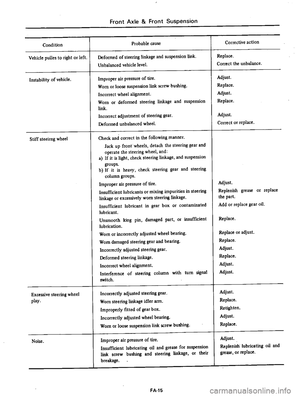
Readjust
Replace
Page 364 of 537

Condition
Vehicle
puBes
to
right
or
left
Instability
of
vehicle
Stiff
steeirng
wheel
Excessive
steering
wheel
play
Noise
Front
Axle
Front
Suspension
Probable
cause
Deformed
of
steering
linkage
and
suspension
link
Unbalanced
vehicle
level
Improper
air
pressure
of
tire
Worn
or
loose
suspension
link
screw
bushing
Incorrect
wheel
alignment
Worn
or
deformed
steering
linkage
and
suspension
link
Incorrect
adjustment
of
steering
gear
Deformed
unbalanced
wheel
Check
and
correct
in
the
following
manner
Jack
up
front
wheels
detach
the
steering
gear
and
operate
the
steering
wheel
and
a
If
it
is
light
check
steering
linkage
and
suspension
groups
b
If
it
is
heavy
check
steering
gear
and
steering
column
groups
Improper
air
pressure
of
tire
Insufficient
lubricants
or
mixing
impurities
in
steering
linkage
or
excessively
worn
steering
linkage
Insufficient
lubricant
in
gear
box
or
contaminated
lubricant
Unsmooth
king
pin
damaged
part
Or
insufficient
lubrication
Worn
or
incorrectly
adjusted
wheel
bearing
Worn
damaged
steering
gear
and
bearing
Incorrectly
adjusted
steering
gear
Deformed
steering
linkage
Incorrect
wheel
alignment
Interference
of
steering
column
with
turn
signal
switch
Incorrectly
adjusted
steering
gear
Worn
steering
linkage
idler
arm
Improperly
fitted
of
gear
box
Incorrectly
adjusted
wheel
bearing
Worn
or
loose
suspension
link
screw
bushing
Improper
air
pressure
of
tire
Insufficient
lubricating
oil
and
grease
for
suspension
link
screw
bushing
and
steering
linkage
or
their
breakage
FA
15
Corrective
action
Replace
Correct
the
unbalance
Adjust
Replace
Adjust
Replace
Adjust
Correct
or
replace
Adjust
Replenish
grease
or
replace
the
part
Add
or
replace
gear
oil
Replace
Replace
or
adjust
Replace
Adjust
Replace
Adjust
Adjust
Adjust
Replace
Retighten
Adjust
Replace
Adjust
Replenish
lubricating
oil
and
grease
or
replace
Page 365 of 537
Condition
Noise
Grating
tire
noise
Jumping
of
disc
wheeL
Excessively
or
partially
worn
tire
Front
Axle
Front
Suspension
Probable
cause
Loose
steering
gear
bolts
linkage
and
suspension
groups
Faulty
shock
absorber
Damaged
wheel
bearing
Worn
steering
linkage
and
steering
gear
Worn
of
loose
suspension
link
screw
bushing
Improper
air
pressure
of
lire
Incorrect
wheel
alignment
Deformed
knuckle
spindle
and
suspension
linkage
Rough
driving
Improper
air
pressure
of
tire
Unbalanced
wheels
Faulty
shock
absorber
Worn
tire
Deformed
wheel
rim
Improper
air
pressure
of
tire
Incorrect
wheel
alignment
Damaged
wheel
bearing
Incorrect
brake
adjustment
Improper
tire
shifting
rotation
Rough
and
improper
wiving
manner
FA
16
Corrective
action
Retighten
Replace
Replace
Replace
Replace
Adjust
Adjust
Replace
Avoid
rough
driving
Adjust
Adjust
Replace
Replace
Replace
Adjust
Adjust
Replace
Adjust
Adjust
Drive
more
gently
Page 366 of 537
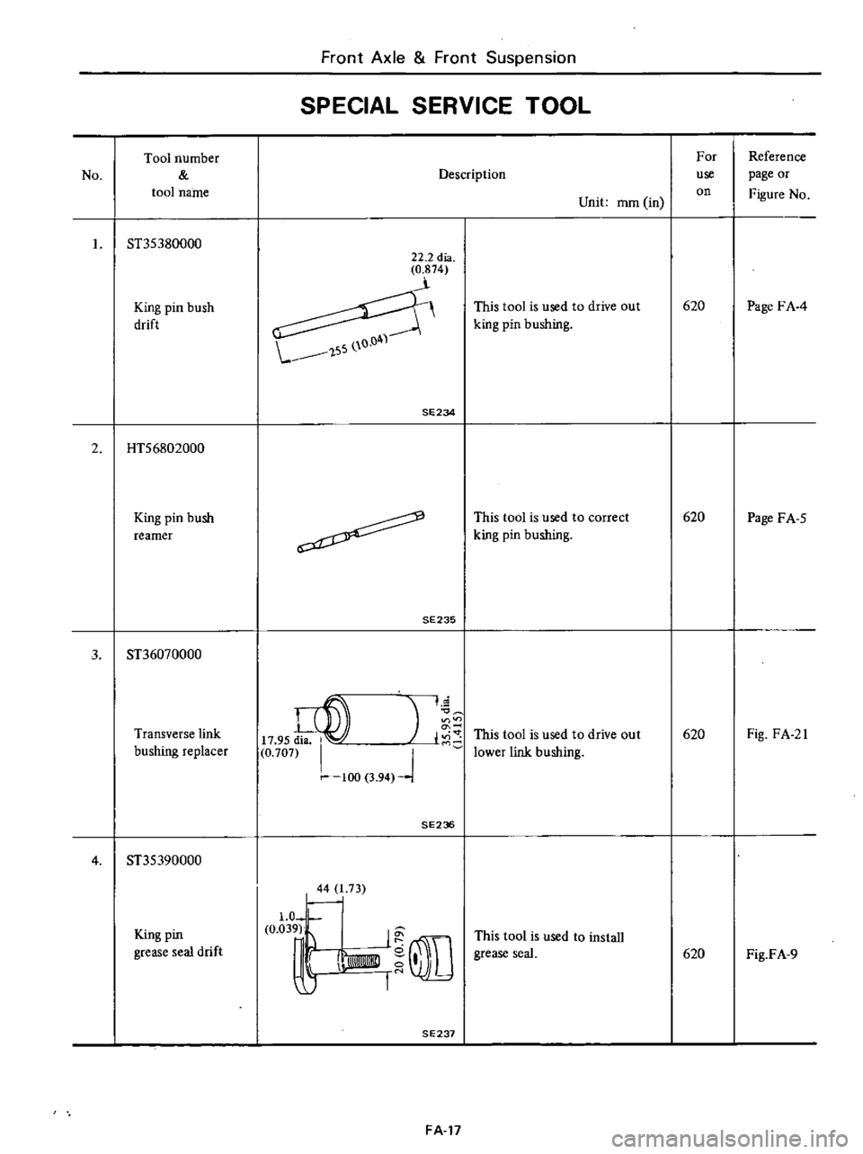
No
Tool
number
tool
name
ST35380000
King
pin
bush
drift
2
HTS6802000
King
pin
bush
reamer
Front
Axle
Front
Suspension
SPECIAL
SERVICE
TOOL
22
2
dia
0
874
SE234
FA
17
Description
Unit
mOl
in
This
tool
is
used
to
drive
out
king
pin
bushing
This
tool
is
used
to
correct
king
pin
bushing
For
use
on
620
620
Reference
page
or
Figure
No
Page
FA
4
Page
FA
S
Page 367 of 537
DATSUN
PICK
UP
MODEL
620
SERIES
I
NISSAN
I
NISSAN
MOTOR
CO
LTD
TOKYO
JAPAN
SECTION
RA
REAR
AXLE
REAR
SUSPENSION
REAR
AXlE
AND
RA
2
REAR
SUSPENSION
SERVICE
DATA
AND
RA
7
SPECIFICATIONS
TROUBLE
DIAGNOSES
RA
8
AND
CORRECTIONS
SPECIAL
SERVICE
TOOLS
RA
9
Page 368 of 537

Rear
Axle
Rear
Suspension
REAR
AXLE
AND
REAR
SUSPENSION
DESCRIPTION
REMOVAL
AND
INSTALLATION
Rear
axle
assembly
Rear
axle
shaft
and
wheel
bearing
Rear
axle
case
Rear
spring
1
1
1
Air
breather
2
Thrust
block
3
Nut
T
3
1
to
4
1
kg
m
22
to
30
ft
lb
4
Shock
absorber
mounting
rubber
bush
5
Rear
spring
clip
V
bolt
6
Rear
axle
oil
seal
spacer
7
Rear
axle
shaft
oil
seal
Supply
wheel
bearing
grease
to
oil
seal
lip
when
assembly
8
Rear
axle
bearing
lock
nut
T
15
to
20
kg
m
10810
145
ft
b
9
Rear
axle
bearing
lock
washer
10
Plain
washer
11
Rear
axle
bearing
cage
12
Road
wheel
bolt
13
Road
wheel
nut
T
8t09kg
m
58
to
65
fl
Ib
CONTENTS
RA
3
RA
3
RA
3
RA
4
RA
5
RA
5
Shock
absorber
tNSPECTION
Rear
axle
shaft
and
wheel
bearing
Rear
axle
case
Rear
spring
Shock
absorber
RA
6
RA
fJ
RA
6
RA6
RA
fJ
RA
fJ
4
I
J
i
I
L
J
@
14
Wheel
bearing
15
Rear
axle
bearing
grease
seat
Supply
wheel
bearing
grease
to
oil
seal
lip
when
assembly
16
Rear
axle
bearing
spacer
17
Rear
axle
shaft
18
Grease
catcher
19
Bearing
cage
bolt
20
Rear
axle
case
end
shim
21
Nut
T
5
4
to
6
4
kg
m
391046
ft
lb
22
Rear
spring
pad
23
Rear
spring
24
Nut
T
7
3
to
9
9
kg
m
53
to
72
ft4b
25
Nut
T
1
610
2
2kg
m
12
to
16
fHb
26
Shock
absorber
rubber
bush
27
Shock
absorber
Fig
RA
I
RA
2
o
RA132
28
Rear
axle
case
29
Filler
ptug
T
6toIOkg
m
43
to
72
ft4b
Oil
capacity
about
1
0
liter
1
US
qt
7
8
Imp
qt
30
Drain
plug
T
6to
10kg
m
43
to
72
fHb
31
Nut
T
11
5
to
13
0
kg
m
83
to
94
fHb
32
Rear
spring
rear
bush
33
Rear
spring
34
Rear
spring
shackle
35
Nut
T
1
1
5
to
13
0
kg
m
83
to
94
fHb
36
Rear
spring
37
Rear
spring
front
bush
38
Rear
spring
front
pin
T
Tightening
torque
Crou
uctional
view
of
rear
a
xl
and
uapension