1976 CHEVROLET MONTE CARLO window
[x] Cancel search: windowPage 3 of 102

Downloaded from www.Manualslib.com manuals search engine ,
BEFORE DRIVING YOUR CHEVROLET
DRIVER CHECKLIST
Before Entering Car
1. See that windows ; mirrors and
lights are clean.
2. Visually note inJIation condition
of tires.
3. Check that area to rear is clear
if about to back up.
Before Driving Off
1. Lock all doors.
2. Position seat, jmd adjust head
restraints, if
so ¢quipped.
3. Adjus!insidean'd outside mirrors.
4. Fasten seat belts.
5. Check that warning bulbs light
when key
is turned to start
position. .
6. Release parking brake ( and see
that brake warning light turns
off). ,
7. Be sure you understand your car
and how
to 'operate it safely.
Keys
Two separate keys are provided
for your car. Each key has a
differ
ent cross section so that it can be
inserted only in certain locks.
• Key with s qua r e hell d
(stamped "e") -for ignition
switch only.
• Key with oval head (stamped
"O")-for all other locks.
,
The code number of each key is
All OTHeR LOCKS
1-1
stamped on the "knock out" plug
in the '
key-bead. Your Chevrolet
dealer removed these plugs
and,.
placed them with the spare set of
keys in the special key envelope
. that was given to you at time of
delivery.
For your protection:
• Record the numbers on the key
envdope and discard the key
plugs.
• Keep the key envelope in a safe
place such
as YOII! wallet, NOT
IN THE CAR.
In the event
the original keys are
lost,
dl!plicates can be made by
your dealer or a locksmith using the
key code information.
Be sure to lock the Klove box
or console
90mpartment and re~
move the key from the car whenever
it is necessary to leave the ignition
key with
an attendant.
Page 5 of 102

Downloaded from www.Manualslib.com manuals search engine Front Seat Back ... ~'""\ ..
Front seat backs on two-door
styles are equipped with a self-lock
ing mechanism to
.• keep the seat
back locked in
phlge while in the
up position. The lock release lever
is located on the upper outboard
portion of the
s~at back.
To tilt the
sell,t back forward,
rotate the levertearward and tilt
the seat back
f?rward. When the
seat back
is r¢turned to the up
position,
• the se~t back will auto
matically 'lock.
Keep
belt re~traints.and buckles
clear of mechanism when tilting
folding seats
forward or backwards,
to help prevent damage
to these
belt systems.
Power Operated Front Seats
The six-way power seat control switch
is located
on the driver's seat
left side panel.
The seat can be operated
as
follows:
I. The front control provides up
and down movement of the
frontof the seat.
2. The center control provides
forward and backward move
ment and up and down move
ment of the entire front seat.
3. The provides up
and of the
Power Windows ,
Power windows have an ignition
interlock
so the windows cannot be
operated unless the ignition switch
is in the "on" position.
1-3
REMINDER: Remove the ignition
key when the vehicle
is not at
tended by a responsible person. A
master control for all windows
is
provided at the driver's position,
Individual switches are provided
under each window for passenger
use.
Inside Rearview Mirrors
Switch mirror to night position
to reduce glare from following
headlights. To raise or lower
mir
ror to achieve desired field of.view,
grasp mirror and exert sufficient
pressure by pushing or pulling up,
down or sideways.
Page 8 of 102

Downloaded from www.Manualslib.com manuals search engine Beit Restraint Bu~zer/Light
Reminder
• When .the ignition key is turp.ed
to On or Start, a ,reminder light
is desigl1ed to come on for four
to eight seconds,
to remind occu
pants to fasten their belt re'
straints.
• If the driver hils not buckled
his belt restraint prior to turning
th~key to On or Start, a buzzer
is . ,designed to sound for four to
, dei~t seco'Yds to remind h.i!I!' to
9 so. ".
If ,the belt restraint system or
reminder system
dOes not work as
described,
see your Chevrolet
dealer for information and
assis
tance.
Lap Belts (For Rear Seat and
Center ·,Fr,on1 Seal
Passengers)
• Seating positions next to side
windows (except station wagon third
seats)
' have retractors
'which ar!) designed to automat
ically take.up¢xcess webbing.
, TIrese beltS should be positioned,
secured
ahd released as described
above undei
"Lap-Shoulder Belt
Combination." (Retractors are
, available as an option on station
wa.gon third seats. ) ,
•
Lap belts at center seating posi
tions
( and third seats) also
should be positioned, secured
and
releaseda.s described above, '
arjd adjusted'fo a SNUG FIT by
pulling on the end of the belt ex
teiiaing froin the adjustable latch
plai~. '
• To .;lengthen.Jap
belt at center
seating
positions (and station
wagonthitd seats) place adjust
able ,latch 'plate
at right angles to
the belt webbing and pull on
latch plate; belt
should then slide
easily thro)lgh the adjus\ment
featute.
r'~
Optional Sho~lder ~elts
(Rear Seat, Outboard)
• Whenptoperlil>vorn with a lap
belt,a shoulde~;belt can provide
l\dditiona.! protej;tion by prevent
ing or minimizing impact with
the car interior;
by restraining
forward rnotion of the upper
torso in a ,collision. This
is par~ ,
ticularlytrue in 'the case of a
frontalforce impact.
Page 15 of 102
Downloaded from www.Manualslib.com manuals search engine STARTING· AND OPERATING
Engine Exhaust Gas Caution (Carbon Monoxide)
Avoid Inhaling exhaust gases because
thay cont./n carbon mODOxlde, which by
1t'811 Is color/e.. and odor/elS. Carbon
monoxIde Is • dangerous gas fh,t can
caus. uneonsC /ousnftu and Is potentially
lelha/.
It at any time you .,u.pect that exhaust _
tumes ., •• nf.rlng'··the passenger com
partment , half' the -cause determined and
co".cfed a. soon as possible. II you must
drlv. under these c6ndltions, drive only
with a/l window. luliy open.
-
The best protection .gainst carbon mon
oxide entry Into the' C81 body Is a properly
maintained' engine exhaust system, car
body and body v.ntllallon syslem. /I Is
recommended tha' the -exhaust system
and body bo Inspecled by a compel"",
mechanic. .
• Each limo rhe vehlcl. I. ralsod lor 011
c"'ng8.
• Whn.If.r " change Is noticed in the
sound 01 IIH1 exhaul' sy~.m.
• Whene"., the ."haust system" 'under
body or TNr ot the .,ehlele is damaged.
S .. 1.0U1 Maintenance Schedule tolder
furn
shed with your .,ehle/. for Inspec
tion procedure .
To allow proper operation ot the car's
ventli.t/on system. keep tront ventilation
Inl.t grme e/hr at .now. I."ves or other
obstruction
.t .11 time,.
SITTING IN A PARKED CAR WITH
ENGINE RUNNING FOR
AN EXTENDED
PERIOD IS NOT RECOMMENDED.
Do not run ,.nglne In confined areas
such as ,garage. ",.iny more than needed
to mOlfe"vehic/. In' or' out of are •. When
v.hlc/ol • • 'opped In an UNCONFINED
ar •• with the engine running tor any more
than a 'short period , adJust he.ting or
cooling sy.tem to toree outside aIr into
car .s tollow,:
1. On cars not equipped with air condi
tioning.
set tan to medium or high
spefKi and upper control lever to any
poslUon oxcepl OFF.
2-1
2. ' On c." equipped with menu.' air call
dltlonlng, 8.t fIn to m.dium or high
speed. upper control lever to any pos;
: tlon except OFF, Ind lower contrOl
I.ver to Iny position except .xtrem •
. ,." COLD.
3. On cara equIpped with automatic a"
conditioning , .et control ,-.,e, to HI
except In hot wNther In .""lch cas.,
set lever In AUTO.
The Irunk lid should be closed while
driving to help prevent Inadvertently draw
Ing exhaust gases Into the car. It I. unwise
to drive .t high speed. for long dUrations
with
the trunk lid open. However, if for
some ,e.son the trunk must remain open
tor a period' whJle moving, or electrical
wiring
or other cabl. connections to a
trailer mu.t PlIS through the seal be
tween trunk lid and bo,dy, the following
precaut~ons shoUld be observed:
• Close all windows.
• Ad/u.t h •• tlng or cooling system to
force outside aIr Into car as described
In nem. 1, 2 and 3 abo,.e but with f.n
.al ., hIgh speod.
• On cats equipped with outside air vents
In or under Instrument panel, open
vonl. lully.
Page 24 of 102
Downloaded from www.Manualslib.com manuals search engine INSTRUMENT PANEL AND CONTROLS
o STANDARD
o OPTIONAL
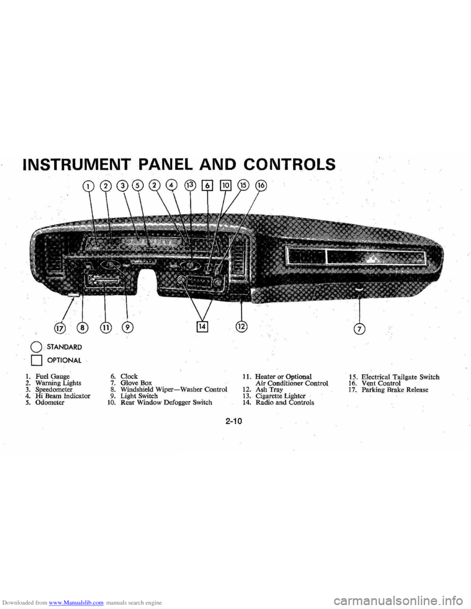
1. Fuel Gauge 2. Warning Lighls 3. Speedometer 4. Hi Beam Indicator 5. Odometer
6. Clock 7. Glove Box 8. Windshield Wiper-Washer COntrol 9. Light Switch to. Rear Window Defogger Switch
11. Heater or Optional
Air Conditioner Control
12. Ash Tray 13. Cigarette Lighter 14. Radio and Controls 1
5 . Electrical Tailgate Switch
16. Vent Control 17. Paridng Brake Release
2-10
Page 32 of 102
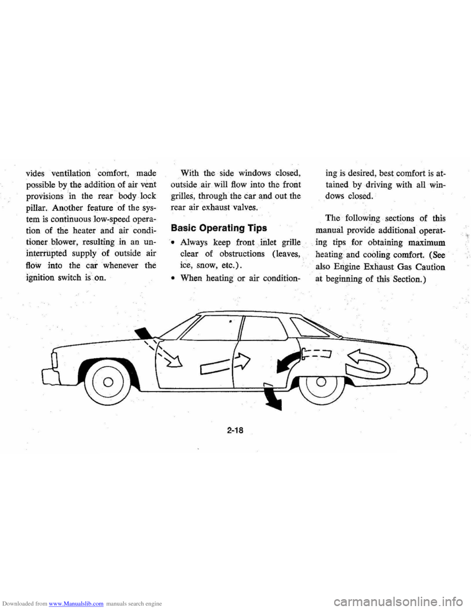
Downloaded from www.Manualslib.com manuals search engine vides ventilation . coillfort , made
possible
by the additionaf air veilt
provisions ' in the rear 1:>ody lock
pillar. Another feature of the
sys
tem is continuous low:speed opera
tion of the heater and air condi
tioner blower , resulting in an un
interrupted
supply of outside air
flOw into the car whenever the
ignition switch is.on. With
the side windows closed,
out side air will
flow into the front
grilles, through the car and out the
rear air exhaust valves.
Basic Operating Tips
'. Always keep front Jnlet grille
clear of obstructions (leaves,
ice, snow, etc.).
• When heating or air condition-
2-18
ingis desired , best comfort is at
tained by driving with all win
dows closed.
The following sections of this
manual provide additional operat-
. ing tips for obtaining maximum
heating and
cooling comfort. (See
also Engine Exnaust Gas Caution
at beginning of
this Seotion.)
Page 33 of 102
Downloaded from www.Manualslib.com manuals search engine Heater
The defrosting and
defogging
systenl assists in provid,
ing good visibility through desig
nated areas of the windshield under
most
inClement'Weather conditions.
For immediate operation of the ve
hicle, the windshield should be
scraped clear.
'
Lower Lever
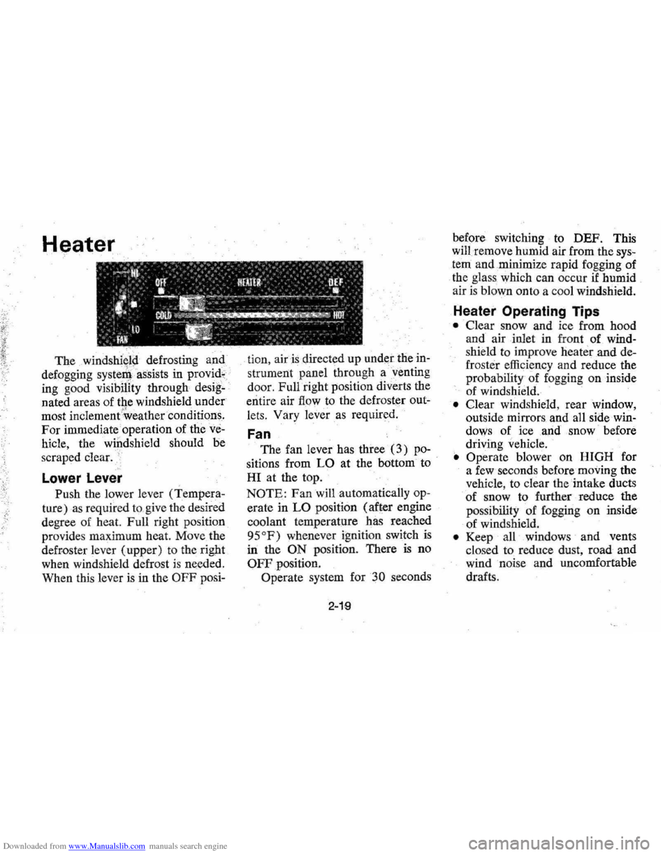
Push the lower lever (Tempera
ture) as required to,give the desired
degree of heat. Full right position
provides maximum heat.
Move the
defroster lever (upper) to the right
when windshield defrost
is needed.
When this lever
is in the OFF posi- tion,
air is directed
up under the in
strument panel through a'venting
door, Full right position diverts the
entire air
flow to the defroster out
lets, Vary
lever as required.
Fan
The fan lever has three (3) po
sitions from LO at the bottom to
HI at the top.
NOTE: Fan will automatically op
erate in LO position (after engine
coolant temperature has reached
95
OF) whenever ignition switch is
in the ON position. There is no
OFF position.
Operate system for
30 seconds
2-19
before switching to DEF. This
will remove humid air from the
sys
tem and ,minimize rapid fogging of
the glass which can occur
if humid
air is blown onto a coo l windshield.
Heater Operating Tips
• Clear snow and ice from hood
and air inlet in front
of wind
shie ld to improve heater and de
frost er efficiency and reduce the
probability of fogging on inside
of windshield.
• Clear windshield, rear window,
outside
mirrors , and all side win
dows of ice ,and snow before
driving vehicle.
• Operate blower on HIGH for
a few seconds before moving the
vehicle, to clear the intake ducts
of snow to further reduce the
pos sibili
ty of fogging on inside
of windshield.
• Keep all windows and vents
clo sed to reduce dust, road and
wind noise and uncomfortable
drafts .
Page 34 of 102
Downloaded from www.Manualslib.com manuals search engine • For most satisfactory heater op
eration and air circulation , oper
ate fan on low or medium speeds
for normal operation and high
s peeds for quick warm -up and
during extremely low
tempera
tures.
• For adeq uate rear sea t he ating,
the area beneath the front seat
mus not be block ed by carpet
ing, rags, paper or oth er mate
rial and fan sh ould operate on
high blower.
Rear Window Defroster
To ensure clear vision through
the rear
window during inclem ent
weather , the Rear Window
De
froster is optionally available. This
unit dr
aws. in air from the pas
senger compart ment and directs it
aga inst the back window to remove
frost or moisture. Its blower h
as a
two-speed control switch on the
instrument panel.
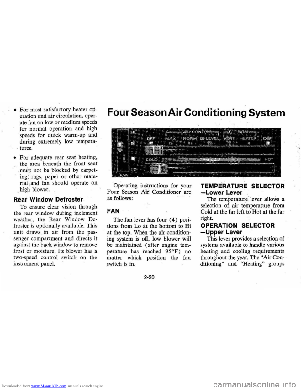
Four Season Air Conditioning System
Operating instructions for your
Four Season Air Conditioner are
a s follows:
FAN
The fan lever has four (4) posi
tions from Lo at the bottom to Hi
at the top. When the air
condition
ing system is off, low blower will
be maintained (after engine
tem
perature has reached 95°F) no
matter which positi on the fan
switch is in.
2-20
TEMPERATURE SELECTOR
-Lower~Lever
The temperature ' lever allows a
selection of air temperature from
Cold at the far left to Hot at the far
right.
OPERATION SELECTOR
-Upper Lever
This lever prov ides a selection of
systems available to handle various
heating and cooling requirements
throughout the year.
The " Air Con-,
ditioning"
an d "He ating" groups