1974 CHEVROLET CAMARO parking brake
[x] Cancel search: parking brakePage 28 of 85
Downloaded from www.Manualslib.com manuals search engine Generator Indicator Light
The red light will go on when
the ignition key
is in the "on" posi
tion, but before the engine
is
started. After the engine starts, the
light should
go out and remain out.
If the light remains on when engine
is running, have your Authorized
Chevrolet Dealer locate and correct
the trouble
as soon as possible.
Engine Temperature
Indicator Light
This indicator light is provided
in the instrument cluster to quickly
warn of an overheated engine. With
the ignition switch in the START
position, the red
TEMP indicator
will light to let you know that it
is
operating properly.
When the engine
is started, the
red light will go out immediately.
It will light up at no other time
unless for some reason the engine
reaches a dangerously high oper
ating temperature.
If the light comes on
during extreme driving condi
tions, such as an extended idle, turn
off the air conditioner (if used) and
run the engine slightly faster than
idle speed with the transmission in
neutral gear.
If the light does not
go off within a short period of time
(1-2 minutes), then turn the engine
off until the cause of the overheat
ing
is corrected. Glance at the in
strument cluster frequently
as you
drive to see
if this light is on.
Brake System Warning
Light
The service brake system is de
signed so that half of the brake
system will provide some braking
action in the event of a hydraulic
leak in the other half of the sys
tem .
If the warning light labeled
"BRAKE, " located at lower left of
instrument cluster (speedometer
face), glows continuously when the
ignition
is on and after the brakes
have been firmly applied it may in-
25
dicate that there is a malfunction
in one half of the brake hydraulic
system .
On cars equipped with
front drum brakes, the light will
go out when foot is removed from
brake pedal.
• As a check on bulb condition
the light should glow with the
parking brake applied and the
ignition on. (Light
is also a
reminder to release parking
brake).
• The light should glow during
engine starting to verify that the
bulb
is operating properly.
• Have system repaired if light
does not come on during check.
• This warning light is not a sub
stitute for the visual check of
brake fluid level required as part
of normal maintenance.
If the light glows red:
• The parking brake control is not
fully released or,
• The service brake system is par
tially inoperative.
Page 29 of 85

Downloaded from www.Manualslib.com manuals search engine What to do:
1. Check that the parking brake is
released. If it is ...
2. Pull off the road and stop, care
fully-remembering that:
• Stopping distances may be
greater.
• Greater pedal effort may be re
quired.
• Pedal travel may be greater.
3.
Tryout brake operation by
starting and stopping on road
shoulder-then:
• If you judge such operation to
be safe, proceed cautiously at a
safe speed to nearest dealer for
repair.
• Or have car towed to dealer for
repair.
Continued operation of the car
in this condition
is dangerous .
. Headlight Beam Indicator
Light
The headlights of your car have
high and low beams to provide you with
proper night-time visibility
for most driving conditions. The
"low" beams are used during most
city driving. The
"high" beams are
especially useful when driving on
dark roads since they provide ex
cellent long range illumination.
The headlight beam indicator will
be on whenever the high beams or
"brights" are in use. The Headlight
Beam
Switch controls the headlight
beams (see Page 22) .
Light Switch
The three position light switch
controls the headlights, taillights,
parking lights, side marker lights,
instrument lights and dome lights
as shown. The headlamp circuit is
protected by a circuit breaker in the
light switch. An overload on the
breaker will cause the lamps
to
"flicker" on and off. If this condi
tion develops, have your headlamp
wiring checked immediately.
PARKING LAMPS
MARKER LAMPS
TURN KNOB TO
VARY INSTRUMENT LIGHTS
FULL Y COUNTER CLOCKWISE FOR DOME LIGHTS
26
HEADLIGHTS PARKING LAMI'S
MARKER LAMPS
Page 40 of 85
Downloaded from www.Manualslib.com manuals search engine than 35 mph, for distances up to
50 miles, provided the drive-line,
axle, transmission, and steering
system are otherwise normally op
erable.
Use only towing equipment
specifically designed for this pur
pose following the instructions of
the towing equipment manufac
turer. A separate safety chain sys
tem must be used.
For such towing
the steering must be unlocked,
transmission in neutral and the
parking brake released. Attach
ments must be made to main struc
tural members of the car. Do not
attach to bumpers
or associated
brackets. Remember that power
brake and power steering assists
will not be available when engine
is inoperative.
Emergency Starting
• Engines in vehicles with auto
matic transmissions cannot be started
by pushing
or towing the
car.
• Never tow a manual transmis
sion-equipped
car to start be
cause the surge forward when
the engine starts could cause a
collision with the tow vehicle.
• A car with a discharged battery
may be started by transferring
electrical power from a battery
in another car -called
"jump
starting."
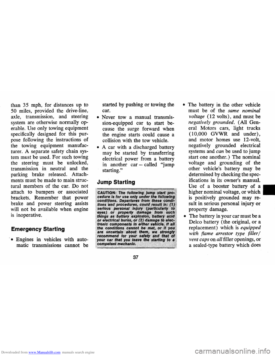
Jump Starting
37
• The battery in the other vehicle
must be of the
same nominal
voltage
(12 volts), and must be
negatively grounded. (All Gen
eral Motors cars, light trucks
(10,000 GVWR and under),
and motor homes use 12-volt,
negatively grounded electrical
systems and
can be used to jump
start one another.) The nominal
voltage and grounding of the
other vehicle's battery may be
determined by checking the spec
ifications
in its owner's manual.
Use of a booster battery of a
higher nominal voltage,
or which
is positively grounded may re
sult
in serious personal injury or
property damage.
• The battery in your car must be a
Delco battery (the original,
or a
replacement) which
is equipped
with flame arrestor type filler/
vent caps
on all filler openings, or
a sealed-type battery which does
Page 41 of 85
Downloaded from www.Manualslib.com manuals search engine not have filler openings or caps.
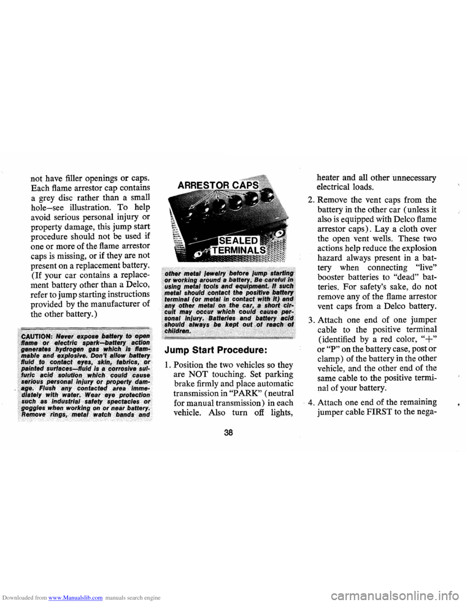
Each flame arrestor cap contains
a grey disc rather than a small
hole-see illustration. To help
avoid serious personal injury or
property damage, this jump start
procedure should not
be used if
one or more of the flame arrestor
caps
is missing, or if they are not
present on a replacement battery.
(If your car contains a replace
ment battery other than a Delco,
refer to jump starting instructions
provided by the manufacturer of
the other battery.)
Jump Start Procedure:
1. Position the two vehicles so they
are
NOT touching. Set parking
brake firmly and place automatic
transmission in
"PARK" (neutral
for manual transmission) in each
vehicle. Also turn
off lights,
38
heater and all other unnecessary
electrical loads.
2. Remove the vent caps from the
battery in the other car (unless it
also
is equipped with Delco flame
arrestor caps). Lay a cloth over
the open vent wells. These two
actions help reduce the explosion
hazard always present in a bat
tery when connecting
"live"
booster batteries to "dead" bat
teries.
For safety's sake, do not
remove any of the flame arrestor
vent caps from a Delco battery.
3. Attach one end of one jumper
cable to the positive terminal
(identified by a red color,
"+"
or "P" on the battery case, post or
clamp) of the battery in the other
vehicle, and the other end of the
same cable to the positive termi
nal of your battery.
- 4. Attach one end of the remaining
jumper cable FIRST to the nega-
Page 42 of 85
Downloaded from www.Manualslib.com manuals search engine tive terminal (black color, "-" Engine Coolant
or "N") of the battery in the other
vehicle, and
THEN the other
end of the same cable to the nega
tive terminal of your battery in
this car. Take care that clamps
from one cable do not inadver
tently touch the clamps on the
other cable. Do not lean over the
battery when making this con
nection.
5. Start the engine in the vehicle
that
is providing the jump start
(if it
was not running). Let run
a
few minutes, then start the en-
gine in the car with the dis-
Jacking Instructions
charged battery.
6. Reverse the above sequence ex
actly when removing the jumper
cables. Reinstall vent caps and
dispose in a safe manner of any
cloths used to cover vent wells,
as
the cloths may have corrosive
acid on them.
39
Preparation
• Park on level surface and set
parking brake firmly.
• Set automatic transmission in
park. (Manual transmission in
reverse).
• Activate hazard warning flasher.
Instructions
1. After removing spare wheel
and tire, jack, jack
base,and
jack handle (wheel nut wrench),
proceed with changing the
wheel
as follows:
2. Remove hub cap
or wheel
cover with flat end of wheel
nut wrench and loosen, but do
not remove nuts, by turning
counterclockwise.
3. With column assembly seated
in base and lever in
"UP" posi
tion,
insert jack hook in
bumper slot.
Page 55 of 85
Downloaded from www.Manualslib.com manuals search engine Front Wheel Bearings
Every 24,000 miles-clean and
repack with a high melting point
wheel bearing lubricant.
Use wheel
bearing lubricant
GM Part No.
1051344 or equivalent. This is a
premium high melting point
lubri
cant. When replacement is neces
sary specify Delco parts.
c. AUT .I . O .. N. : ."LO .. ng . fibre" ... ot"vi.SC .. 0USI' .. ty .pe
lubricant . sho.uld . not be.used. DO not . mix wheel bearing lubricants. Be sure to thoroughlyclean bearings and hubs(jf all old lubricant betore repac/dng .
Brakes
Brake linings should be periodi
cally inspected for wear by a quali
fied technician. The frequency of
this inspection
depe:pds upon driv
ing conditions such as traffic or
terrain, and also the driving
tech
niques of individual owners. Your
Chevrolet Dealer
is best qualified
to advise you
as to how often this
inspection should be performed. When
replacement
is required,
specify GM and Delco parts.
Master Cylinder -Every 6,000
miles or 4 months -Check fluid
level
in each reservoir and main
tain ~" below lowest edge of each
filler opening with Delco
Supreme
No. 11 or DOT-3 hydraulic brake
fluid .
Parking Brake Pulley, Cables
and Linkage~Every 6,000 miles
or 4
months-Apply water resist
ant EP Chassis Lubricant which
meets GM Specification
6031 M, to
parking brake cable at cable guides
and at all operating links and levers.
Standard Steering Gear
The steering gear is factory
filled with steering gear lubricant.
Seasonal change of this lubricant
should not be performed and the
housing should not be
drained-no
lubrication is required for the life
of the steering gear.
Every 36,000 miles, the gear
52
should be inspected for seal leak
age (actual solid grease-not just
oily film).
If a seal is replaced or
the gear is overhauled, the gear
housing should be refilled with
Part No.
1051052 (13 oz. con
ta iner ) Steering Gear Lubricant
which meets GM Specification GM
4673M, or its equivalent.
NOTE: Do not use EP, Chassis
Lube, meeting GM Specification
GM
6031 M , to lubricate the gear.
DO NOT OVER-FILL the gear
housing.
Power Steering System
Check the fluid level in the
pump reservoir at each oil change
period. Add GM Power Steering
Fluid (or
DEXRON®-II or DEX
RON® Automatic Transmissiol1
Fluid) as necessary to bring level
into proper range on filler cap
in
dicator depending upon fluid tem
perature.
Page 66 of 85
Downloaded from www.Manualslib.com manuals search engine Tire Replacement
Mounting of the Space Saver
Spare Tire by other than authorized
tire dealers
is not recommended.
Improper mounting can cause
vio
lent bursting of the tire away from
the wheel which can result in serious
personal injury.
Underbody Maintenance
The effects of salt and other
corrosive materials used for ice
and snow removal and dust
con
trol can result in accelerated rust
ing and deterioration of under
body components such
as brake
and fuel lines, frame, underbody
floor pan, exhaust system, brac
kets , parking brake cables. These
corrosive effects, however, can be
reduced by periodic flushing of the underbody
with plain water. In
geographic areas having a heavy
concentration of such corrosive
materials,
it is recommended that
the complete underbody be
in
spected and flushed at least once
each year, preferably after a
win
ter's exposure. Particular attention
should be given to cleaning out
underbody members where dirt
and other foreign materials may
have collected.
If desired, your Chevrolet deal
er can perform this service for
you.
In addition, he can provide
recommendations on undercoat
ing materials which will help
pro
tect your vehicle from corrosion.
Battery Care (Energizer)
Check fluid level monthly. If the
fluid level
is low, add only color-
63
less, odorless drinking water or dis
tilled water to bring level to split
ring in filler opening.
Page 76 of 85
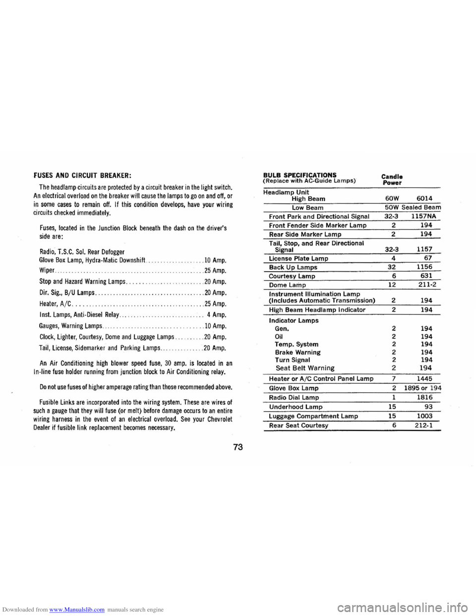
Downloaded from www.Manualslib.com manuals search engine FUSES AND CIRCUIT BREAKER:
The head lamp circuit s are protected by a circuit breaker in the light switch.
An electrical overload on the breaker will cause the lamps to go on and off, or
in some cases to remain off. If this condition develops, have your wiring circuits checked immediately.
Fuses, located in the Junction Block beneath the dash on the driver's side are:
Radio, T.S.C. Sol. Rear Defogger Glove Box Lamp, Hydra·Matic Downshift ...
Wiper ..
.10 Amp.
... 25 Amp.
Stop and Hazard Warning Lamps. . . . . . ... . ........ 20 Amp.
Dir. Sig., B/U Lamps........... ............. ... .. . ... 20 Amp.
Heater, A /C .... . .25 Amp.
Inst. Lamps, Anti-Diesel Relay............. ....... . .. 4 Amp.
Gauges, Warning Lamps ......................... 10 Amp.
Clock, Lighter, Courtesy, Dome and Luggage Lamps. . .20 Amp.
Taii, License, Sidemarker and Parking Lamps ... ..... 20 Amp.
An Air Conditioning high blower speed fuse, 30 amp. is located in an
In-line fuse holder running from junction block to Air Conditioning relay.
Do not use fuses of higher amperage rating than those recommended above.
Fusible Links are incorporated into the wiring system. These are wires of such a gauge that they will fuse (or melt) before damage occurs to an entire
wiring harness in the event of an electrical overload. See your Chevrolet Dealer if fusible link replacement becomes necessary.
73
BULB SPECIFICATIONS (Replace with AC·Guide Lamps)
Headlamp Unit High Beam
low Beam
Front Park
and Directional Signal
Front Fender Side Marker lamp
Rear Side Marker lamp
Tail, Stop, and Rear Directional Signal
license Plate lamp
Back Up lamps
Courtesy lamp
Dome Lamp
Instrument Illumination lamp (Includes Automatic Transmission)
High Beam
Headlamp Indicator
Indicator lamps Gen. Oil Temp. System
Brake Warning
Turn Signal Seat Belt Warning
Heater or AIC Control Panel lamp
Glove Box lamp
Radio Dial lamp
Underhood lamp
luggage Compartment lamp
Rear Seat Courtesy
Candle
Power
60W 6014
50W Sealed Beam
32·3 1157NA
? 194
2 194
32·3 1157
4 67
32 1156
6 631
12 211·2
2 194
2 194
2 194 2 194 2 194 2 194 2 194 2 194
7 1445
2 1895 or 194
1 1816
15 93
15 1003
6 212-1