1974 CHEVROLET CAMARO brake
[x] Cancel search: brakePage 22 of 85
Downloaded from www.Manualslib.com manuals search engine In a normal turning situation
such
as turning a corner, the turn
signal
is cancelled automatically
after the turn
is completed. How
ever, in some driving maneuvers
such
as changing lanes on an ex
pressway, the steering wheel
is not
turned back sufficiently after com
pleting the turn to automatically
cancel the turn signal. For con
venience in such maneuvers, the
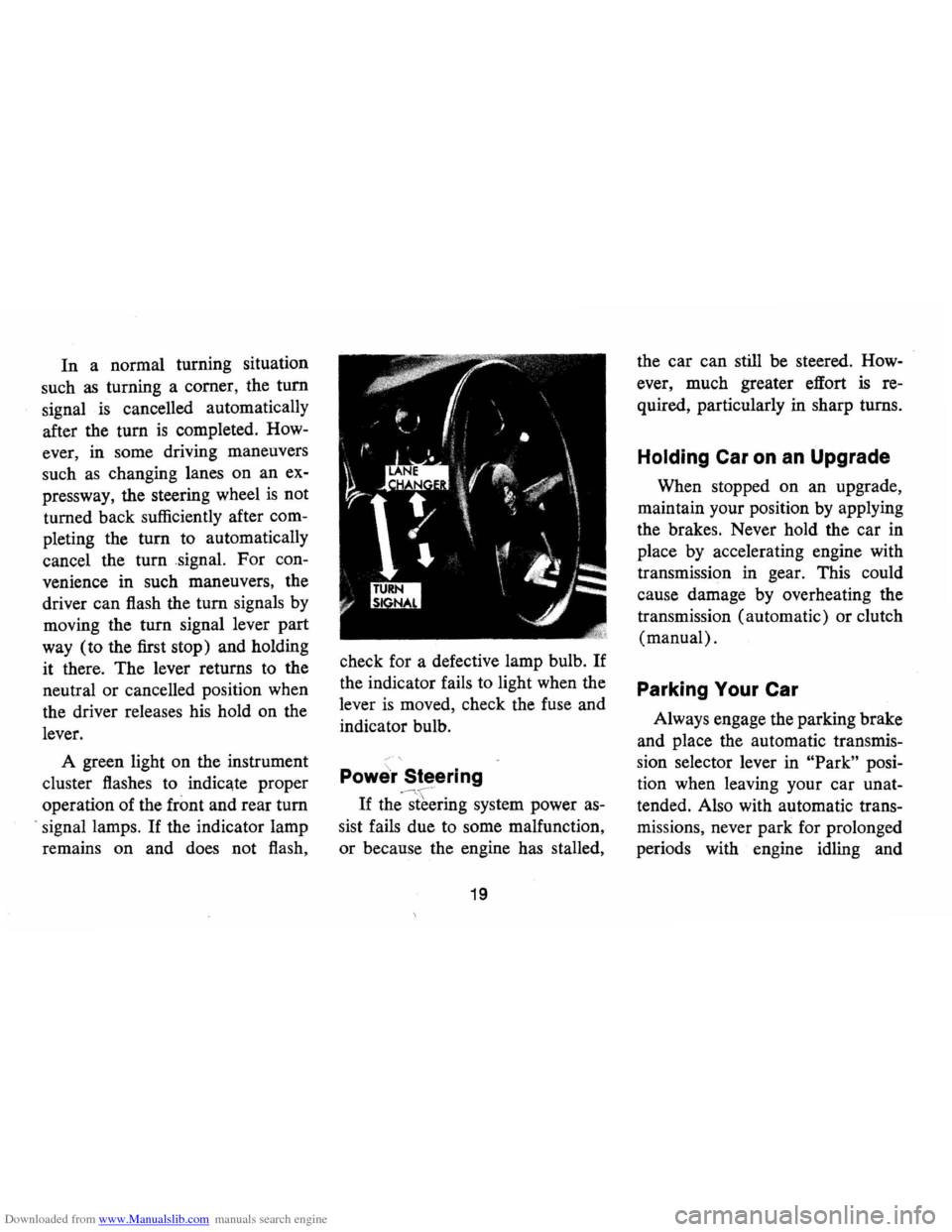
driver can flash the turn signals by
moving the turn signal lever part
way (to the first stop) and holding
it there. The lever returns to the
neutral or cancelled position when
the driver releases his hold on the
lever.
A green light on the instrument
cluster flashes to indicate proper
operation of the
front and rear tum
> signal lamps. If the indicator lamp
remains on and does not flash, check
for a defective lamp bulb.
If
the indicator fails to light when the
lever
is moved, check the fuse and
indicator bulb.
Powe'r Steering
If
the'-~[~~ring system power as
sist fails due to some malfunction,
or because the engine has stalled,
19
the car can still be steered. How
ever, much greater effort
is re
quired, particularly in sharp turns.
Holding Car on an Upgrade
When stopped on an upgrade,
maintain your position by applying
the brakes. Never hold the car in
place by accelerating engine with
transmission in gear. This could
cause damage by overheating the
transmission (automatic) or clutch
(manual).
Parking Your Car
Always engage the parking brake
and place the automatic transmis
sion selector lever in
"Park" posi
tion when leaving your car unat
tended. Also with automatic trans
missions, never park for prolonged
periods with engine idling and
Page 24 of 85
Downloaded from www.Manualslib.com manuals search engine FLOOR CONTROLS
Braking System
The service brake system is de
signed for braking performance
under a wide range of driving con
ditions even when the vehicle
is
loaded to its full rated vehicle load.
Power Brakes
• On cars with power brakes if
power assist to the brakes
is in
terrupted due to a stalled engine
or some malfunction, two or
more brake applications nor
mally can be made using reserve
power.
• If the brake pedal is held down,
the system
is designed to bring
the car to a full stop on reserve
power. However, the reserve
power
is partially depleted each
time the brake pedal is applied
and released. Do not pump
brakes when brake power assist
has been interrupted.
• When reserve power is ex
hausted, the vehicle can still be
stopped by applying greater
force to the pedal.
Parking Brake
• To set parking brake, fully de
press foot pedal at far left side.
• For maximum holding power,
depress regular brake pedal with
the other foot at the same time.
• To release parking brake, pull
"BRAKE RELEASE" lever on
lower left instrument panel.
• As a reminder, the brake system
warning light
is designed to glow
whenever the parking brake con-
21
trol is not fully released, and the
ignition
is on.
• Never drive car with parking
brake set
as this may overheat or
otherwise damage rear brakes.
NOTE: "Riding the brake" by rest
ing your foot on the brake pedal
when not intending to brake can
cause abnormally high brake tem
peratures, excessive lining wear
and possible damage to the brakes.
Page 25 of 85
Downloaded from www.Manualslib.com manuals search engine REMINDER: Cars equipped with
front disc brakes have a built-in
wear indicator that
is designed to
make a high frequency, squealing,
or cricket-like warning sound when
the linings are worn to where re
placement
is required. The sound
will occur intermittently or con
tinuously when wheels are rolling,
but will change or cease completely
when the brake pedal
is applied
firmly.
See also the various brake
checks listed in the Chevrolet main
tenance schedule folder.
Automatic Brake Adjusters
• Brakes on this car (except for
the parking brake) are self
adjusting, designed to eliminate
periodic brake adjustments .
• Drum brake adjustment is made
automatically
as the brakes are
applied while car
is moving
backwards .
• Disc brake adjustment is made
automatically with each brake
application.
• If excess brake pedal travel de
velops, drive alternately back
ward and forward several times
and apply brakes firmly in each
direction.
• See your dealer if normal pedal
travel
is not restored, or if there
is a rapid increase in pedal travel,
which could be a sign of other
brake
trOUble.
Clutch Adjustment
Clutch adjustment should be
checked and adjusted periodically
as necessary to compensate for
22
clutch facing wear. To check, de
press pedal by hand until resistance
is felt. Free travel of pedal should
be approximately one inch; if very
little or no free travel
is evident,
clutch adjustment
is required.
Headlight Beam Switch
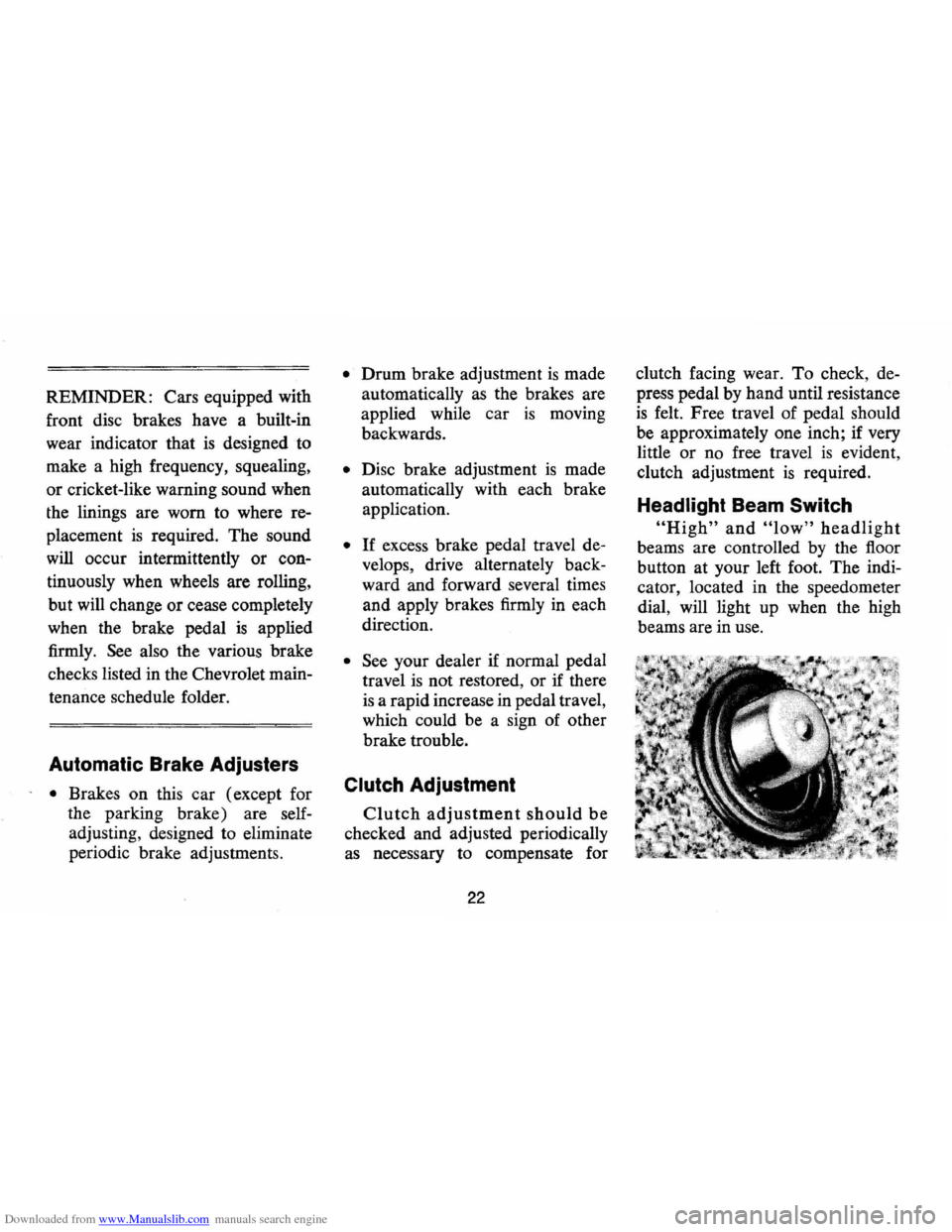
"High" and "low" headlight
beams are controlled by the floor
button at your left foot. The indi
cator, located in the speedometer
dial, will light up when the high
beams are in use.
Page 28 of 85
Downloaded from www.Manualslib.com manuals search engine Generator Indicator Light
The red light will go on when
the ignition key
is in the "on" posi
tion, but before the engine
is
started. After the engine starts, the
light should
go out and remain out.
If the light remains on when engine
is running, have your Authorized
Chevrolet Dealer locate and correct
the trouble
as soon as possible.
Engine Temperature
Indicator Light
This indicator light is provided
in the instrument cluster to quickly
warn of an overheated engine. With
the ignition switch in the START
position, the red
TEMP indicator
will light to let you know that it
is
operating properly.
When the engine
is started, the
red light will go out immediately.
It will light up at no other time
unless for some reason the engine
reaches a dangerously high oper
ating temperature.
If the light comes on
during extreme driving condi
tions, such as an extended idle, turn
off the air conditioner (if used) and
run the engine slightly faster than
idle speed with the transmission in
neutral gear.
If the light does not
go off within a short period of time
(1-2 minutes), then turn the engine
off until the cause of the overheat
ing
is corrected. Glance at the in
strument cluster frequently
as you
drive to see
if this light is on.
Brake System Warning
Light
The service brake system is de
signed so that half of the brake
system will provide some braking
action in the event of a hydraulic
leak in the other half of the sys
tem .
If the warning light labeled
"BRAKE, " located at lower left of
instrument cluster (speedometer
face), glows continuously when the
ignition
is on and after the brakes
have been firmly applied it may in-
25
dicate that there is a malfunction
in one half of the brake hydraulic
system .
On cars equipped with
front drum brakes, the light will
go out when foot is removed from
brake pedal.
• As a check on bulb condition
the light should glow with the
parking brake applied and the
ignition on. (Light
is also a
reminder to release parking
brake).
• The light should glow during
engine starting to verify that the
bulb
is operating properly.
• Have system repaired if light
does not come on during check.
• This warning light is not a sub
stitute for the visual check of
brake fluid level required as part
of normal maintenance.
If the light glows red:
• The parking brake control is not
fully released or,
• The service brake system is par
tially inoperative.
Page 29 of 85

Downloaded from www.Manualslib.com manuals search engine What to do:
1. Check that the parking brake is
released. If it is ...
2. Pull off the road and stop, care
fully-remembering that:
• Stopping distances may be
greater.
• Greater pedal effort may be re
quired.
• Pedal travel may be greater.
3.
Tryout brake operation by
starting and stopping on road
shoulder-then:
• If you judge such operation to
be safe, proceed cautiously at a
safe speed to nearest dealer for
repair.
• Or have car towed to dealer for
repair.
Continued operation of the car
in this condition
is dangerous .
. Headlight Beam Indicator
Light
The headlights of your car have
high and low beams to provide you with
proper night-time visibility
for most driving conditions. The
"low" beams are used during most
city driving. The
"high" beams are
especially useful when driving on
dark roads since they provide ex
cellent long range illumination.
The headlight beam indicator will
be on whenever the high beams or
"brights" are in use. The Headlight
Beam
Switch controls the headlight
beams (see Page 22) .
Light Switch
The three position light switch
controls the headlights, taillights,
parking lights, side marker lights,
instrument lights and dome lights
as shown. The headlamp circuit is
protected by a circuit breaker in the
light switch. An overload on the
breaker will cause the lamps
to
"flicker" on and off. If this condi
tion develops, have your headlamp
wiring checked immediately.
PARKING LAMPS
MARKER LAMPS
TURN KNOB TO
VARY INSTRUMENT LIGHTS
FULL Y COUNTER CLOCKWISE FOR DOME LIGHTS
26
HEADLIGHTS PARKING LAMI'S
MARKER LAMPS
Page 39 of 85
Downloaded from www.Manualslib.com manuals search engine I n Case of Emergency
Four-Way Hazard
Warning
Flasher
• Use the warning flasher to warn
other drivers any time your
vehicle becomes a traffic hazard,
day
or night.
• Avoid stopping on the roadway
if possible.
• Turn on the hazard warning
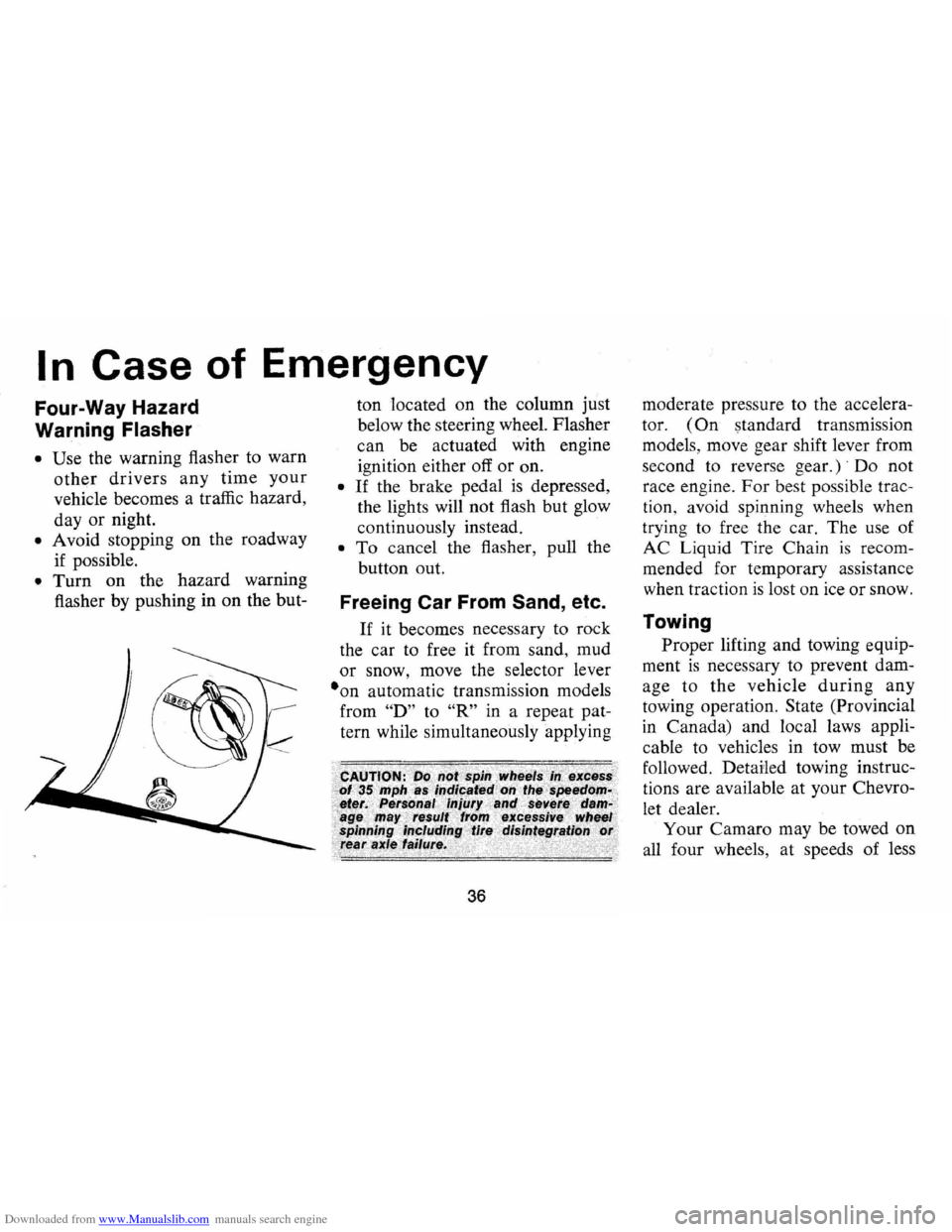
flasher by pushing in on the but- ton
located on the column just
below the steering wheel. Flasher
can be actuated with engine
ignition either off
or on.
• If the brake pedal is depressed,
the lights will not flash but glow
continuously instead.
• To cancel the flasher, pull the
button out.
Freeing Car From Sand, etc.
If it becomes necessary to rock
the car to free it from sand, mud
or snow, move the selector lever
·on automatic transmission models
from
"D" to "R" in a repeat pat
tern while simultaneously applying
36
moderate pressure to the accelera
tor.
(On standard transmission
models, move gear shift lever from
second to reverse
gear.)' Do not
race engine.
For best possible trac
tion, avoid spinning wheels when
trying to free the car. The use of
AC Liquid Tire Chain
is recom
mended for temporary assistance
when traction
is lost on ice or snow.
Towing
Proper lifting and towing equip
ment
is necessary to prevent dam
age to
the vehicle during any
towing operation. State (Provincial
in Canada) and local laws appli
cable to vehicles in tow must be
followed. Detailed towing instruc
tions are available at your Chevro
let dealer.
Your Camaro may be towed on
all four wheels, at speeds of less
Page 40 of 85
Downloaded from www.Manualslib.com manuals search engine than 35 mph, for distances up to
50 miles, provided the drive-line,
axle, transmission, and steering
system are otherwise normally op
erable.
Use only towing equipment
specifically designed for this pur
pose following the instructions of
the towing equipment manufac
turer. A separate safety chain sys
tem must be used.
For such towing
the steering must be unlocked,
transmission in neutral and the
parking brake released. Attach
ments must be made to main struc
tural members of the car. Do not
attach to bumpers
or associated
brackets. Remember that power
brake and power steering assists
will not be available when engine
is inoperative.
Emergency Starting
• Engines in vehicles with auto
matic transmissions cannot be started
by pushing
or towing the
car.
• Never tow a manual transmis
sion-equipped
car to start be
cause the surge forward when
the engine starts could cause a
collision with the tow vehicle.
• A car with a discharged battery
may be started by transferring
electrical power from a battery
in another car -called
"jump
starting."
Jump Starting
37
• The battery in the other vehicle
must be of the
same nominal
voltage
(12 volts), and must be
negatively grounded. (All Gen
eral Motors cars, light trucks
(10,000 GVWR and under),
and motor homes use 12-volt,
negatively grounded electrical
systems and
can be used to jump
start one another.) The nominal
voltage and grounding of the
other vehicle's battery may be
determined by checking the spec
ifications
in its owner's manual.
Use of a booster battery of a
higher nominal voltage,
or which
is positively grounded may re
sult
in serious personal injury or
property damage.
• The battery in your car must be a
Delco battery (the original,
or a
replacement) which
is equipped
with flame arrestor type filler/
vent caps
on all filler openings, or
a sealed-type battery which does
Page 41 of 85
Downloaded from www.Manualslib.com manuals search engine not have filler openings or caps.
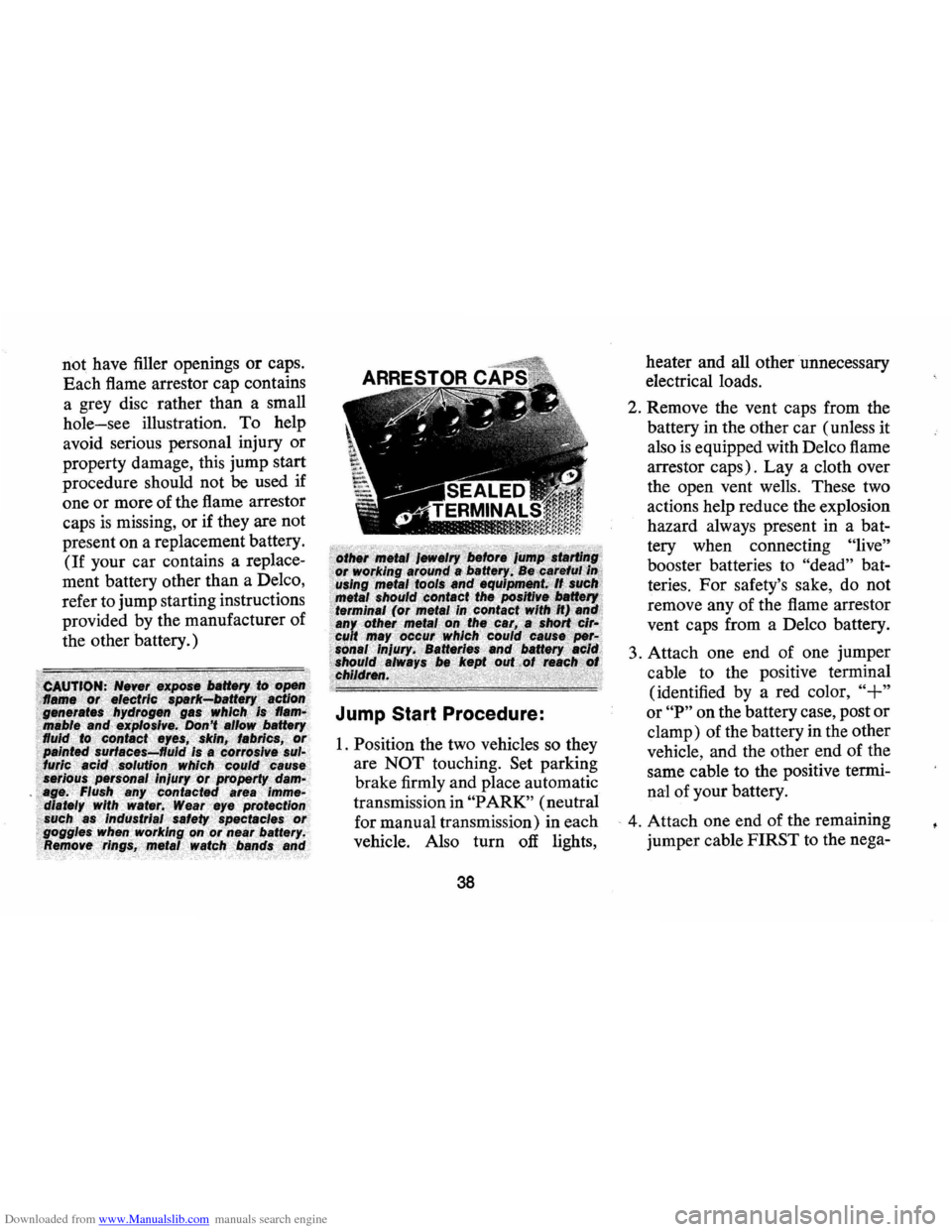
Each flame arrestor cap contains
a grey disc rather than a small
hole-see illustration. To help
avoid serious personal injury or
property damage, this jump start
procedure should not
be used if
one or more of the flame arrestor
caps
is missing, or if they are not
present on a replacement battery.
(If your car contains a replace
ment battery other than a Delco,
refer to jump starting instructions
provided by the manufacturer of
the other battery.)
Jump Start Procedure:
1. Position the two vehicles so they
are
NOT touching. Set parking
brake firmly and place automatic
transmission in
"PARK" (neutral
for manual transmission) in each
vehicle. Also turn
off lights,
38
heater and all other unnecessary
electrical loads.
2. Remove the vent caps from the
battery in the other car (unless it
also
is equipped with Delco flame
arrestor caps). Lay a cloth over
the open vent wells. These two
actions help reduce the explosion
hazard always present in a bat
tery when connecting
"live"
booster batteries to "dead" bat
teries.
For safety's sake, do not
remove any of the flame arrestor
vent caps from a Delco battery.
3. Attach one end of one jumper
cable to the positive terminal
(identified by a red color,
"+"
or "P" on the battery case, post or
clamp) of the battery in the other
vehicle, and the other end of the
same cable to the positive termi
nal of your battery.
- 4. Attach one end of the remaining
jumper cable FIRST to the nega-