1973 CHEVROLET MONTE CARLO tow
[x] Cancel search: towPage 6 of 86
Downloaded from www.Manualslib.com manuals search engine Door Locks
Front side doors can be locked
from the inside by depressing the
passenger guard door lock buttons
located on the upper door panel.
All doors can be locked from the
outside by first depressing the door
lock button and closing the door.
The front doors can also be
locked by using the key.
All models have
as a standard
safety feature overriding door locks.
When the doors are locked, the
door latch mechanism
is inopera
tive, preventing inadvertent open
ing of the door by movement of the
inside handle.
REMINDER: Avoid hanging ob
jects on the right hand coat hook
in such a way that you block the
driver's vision to the right rear
quarter.
REMINDER: Always lock the
doors when driving, for greater se
curity in the event of an accident
and for security against entry by
unwelcome persons while momen
tarily stopped.
Seats
Folding seatbacks are equipped
with self-latching mechanisms and
release controls designed for the
convenience of entering and exit
ing passengers.
Manually Operated Front Seats
-The front seat can be moved
forward or rearward by moving the
control lever on the driver's side
of the seat forward and exerting
slight body pressure in the direc
tion desired. Release the lever
so
the seat will lock in the desired
position.
Back Locks-For your safety each
folding front seatback has a lock
4
which must be released before the
seatback can be folded forward.
The release lever
is located at the
lower side of each backrest nearest
the door. Move the lever upward,
then pull the seatback forward.
Keep seat belts and
bu.c~les
clear of mechanism when tlltmg
folding seats forward or backwards,
to prevent damage to these belt
restraints.
Bucket Seats
The front seats may be adjusted
to suit an individual's preference.
Simply release the seat lock mech
anism located at the front of the
seat.
Once released, exert slight
body pressure in the direction de
sired. Release the lever so the seat
will lock in the desired position.
Swivel Bucket Seats
The swivel bucket seat can be
turned towards the door opening
Page 11 of 86
Downloaded from www.Manualslib.com manuals search engine • To fasten the shoulder belt, un
stow it and place the knob on
the shoulder belt end in the
keyhole on the lap belt latch
plate. (The latch
is designed so
that this attachment can only be
completed before fastening the
lap belt.) Tilt the knob as neces
sary, to pass
it through the slot.
Pull the knob firmly upward to
seat it at the narrow end of the
keyhole, then fasten the lap belt.
• Shoulder belts are lengthened
and shortened in the same man
ner
as center seat lap belts.
• Shoulder belt should have suf
ficient slack to insert a fist's
width between your chest and
the belt. This can be checked
by inserting a clenched
fist be
tween the belt and your chest
with thumb against chest and
back of hand facing upward.
• When not in use, the shoulder
SHOULDER BELT
STOWAGE
9
belt may be stowed by leaving
it attached to the lap belt and
allowing the lap belt to rewind
into its retractor.
Take up re
maining slack using the shoul
der belt adjustment feature.
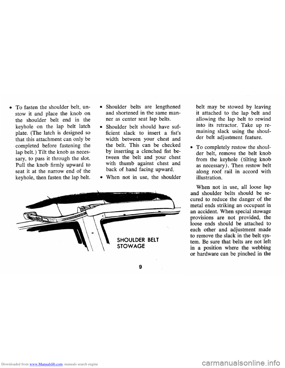
• .To completely restow the shoul
der belt, remove the belt knob
from the keyhole (tilting knob
as necessary). Then restow belt
along roof rail in accord with
illustration.
When not in use, all loose lap
and shoulder belts should be se
cured to reduce the danger of the
metal ends striking an occupant in
an accident. When special stowage
provisions are not provided, the
loose ends should be attached to
each other and adjustment made
to remove the slack in the belt sys
tem. Be sure that belts are not left
in a position where the webbing
or hardware can be pinched in the
Page 12 of 86
Downloaded from www.Manualslib.com manuals search engine seat structure or door, and thus
become damaged.
Seat Belt Inspection
• Periodically inspect belts, buck
les, retractors , and anchors for
damage that could lessen the
effectiveness of the restraint
system.
• Keep sharp edges and damaging
objects away from belts.
• Replace belts if cut, weakened,
frayed ,
or subjected to collision
loads.
• Check that anchor mounting
bolts are tight.
• Have questionable parts re
placed.
• Keep seat belts clean and dry.
• Clean only with mild soap solu
tion
and lukewarm water.
• Do not bleach or dye belts since
this may severely weaken belts.
Head Restraints
• Head restraints are designed to
help reduce injuries due to
"whiplash ."
• Select
one of the three positions
-full up, intermediate , or full
down-which places the top of
the head restraint closest to the
top of your ears.
• Do not use head restraint above
the full up
"detent" position.
• Head restraint can be raised by
pulling up until you feel it click
into the
"detent" at the inter
mediate position.
• To raise further, or to lower,
release latch at base of support
ing rod and push up
or down on
restraint.
• Do not operate vehicle with head
restraints removed, since occu
pants lose the protection pro
vided.
10
Child Restraint
Children in automobiles should
be restrained to lessen the risk of
injury in accidents, sudden stops
or other hazardous situations. Gen
eral motors dealers offer restraint
systems designed specifically for
use with infants.
In using any in
fant
or child restraint system, read
. and comply with all installation
'and usage instructions.
All unused seat belts near the
child should be stowed properly
to help prevent them from striking
him in the event of an accident.
Lap belts and shoulder belts with
out stowage provisions should
have buckles latched and belts
adjusted to remove slack.
Cars Not Equipped With
Special Child Restraints
If a child is traveling in a ve
hicle not equipped with a General
Motors infant restraint
or other
Page 13 of 86
Downloaded from www.Manualslib.com manuals search engine safe infant or child restraint sys
tem, the following precautions
should be taken:
1. Infants unable to sit up by them
selves should be restrained by
placing them in a covered,
padded bassinet which is placed
crossways in the vehicle (width
wise) on the rear seat. The
bassinet should be securely
restrained with the regular
ve
hicle seat belts. An alternate
method
is to position the bas
sinet so that it rests against the
front seat, again crossways in
Trailer Hauling
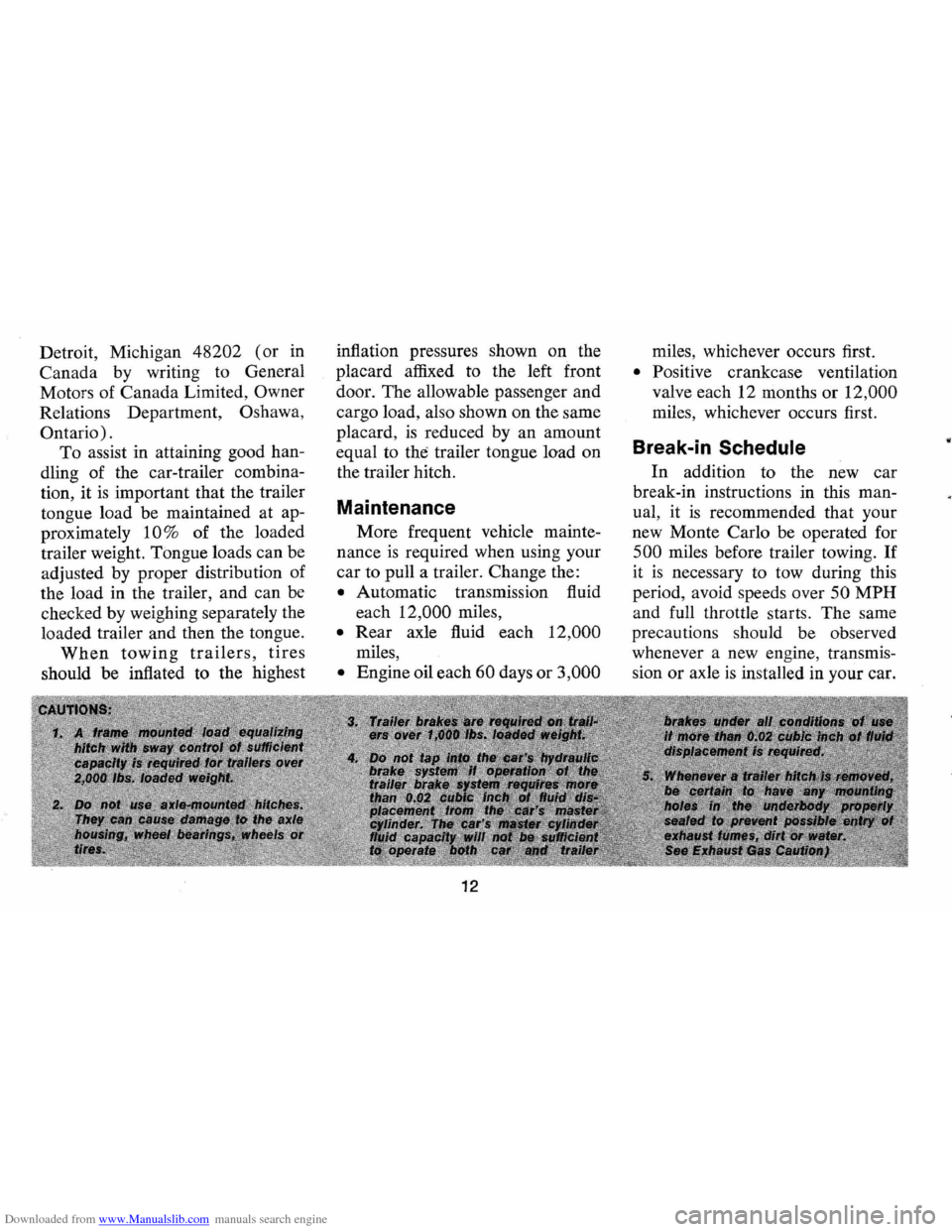
Since passenger cars are de
signed and intended to be used pri
marily as passenger conveyances,
towing a trailer will affect handling,
durability
and economy. Maximum
safety and satisfaction depends the
vehicle.
2. Children able to sit up by them
selves should be placed on a
seat and lap belted, preferably
in the rear seat. Never allow a
child to stand
or kneel on any
seat.
If the child cannot see out
the car windows he should sit
on a firm cushion with the regu
lar lap belt restraining him at
the hips. The cushion should be
as firm as practical and just high
enough to enable the child to
look horizontally out of the car
windows. The use of the cush-
upon proper use of correct equip
ment and avoiding overloads and
other abusive operation.
The maximum loaded trailer
weight which you can pull with
your Monte Carlo depends on what
special equipment has been in
stalled on your car. Chevrolet does
11
ion should be discontinued as
soon as the child is old enough
to see out of the car windows
without it.
3. General Motors recommends
that children be restrained prop
erly when riding. However, if
unusual conditions prohibit use
of restraints and require that a
child must stand, he should
stand on the floor directly be
hind the front seat. This will
help minimize the possibility of
injury from frontal impacts
III
the event of an accident.
not recommend towing any trailer
unless the car
is properly equipped.
Information on trailer hauling
capabilities, special equipment re
quired, and optional equipment
offered by Chevrolet
is available
from your Chevrolet Dealer
or by
writing Chevrolet Motor Division,
Page 14 of 86
Downloaded from www.Manualslib.com manuals search engine Detroit, Michigan 48202 (or in
Canada by writing to General
Moto rs of Canada Limited,
Owner
Relations Department , Oshawa,
Ontario) .
To assist in attaining good han
dling of the car-trailer combina
tion, it
is important that the trailer
tongue load be maintained at ap
proximately
10% of the loaded
trailer weight. Tongue loads can be
adjusted by proper distribution of
the load in the trailer, and can be
checked by weighing separately the
loaded trailer and then the tongue.
When towing trailers, tires
should be inflated to the highest inflation
pressures shown on the
placard affixed to the left front
door . The allowable passenger and
cargo load, also shown on the same
placard ,
is reduced by an amount
equal to
the trailer tongue load on
the trailer hitch.
Maintenance
More frequent vehicle mainte
nance
is required when using your
car to pull a trailer. Change the:
• Automatic transmission fluid
each
12 ,000 miles ,
• Rear axle fluid each 12,000
miles,
• Engine oil each 60 days or 3,000
12
miles , whichever occurs first.
• Positive crankcase ventilation
valve each 12 months or
12,000
miles, whichever occurs first.
Break-in Schedule
In addition to the new ca r
break-in instructions in this man
ual, it
is recommended that your
new Monte Carlo be operated for
500 miles before trailer towing. If
it is necessary to tow during this
period , avoid speeds over
50 MPH
and full throttle starts. The same
precautions should be observed
whenever a new engine, transmis
sion or axle
is installed in your car.
Page 17 of 86

Downloaded from www.Manualslib.com manuals search engine STEERING COLUMN CONTROLS
Anti-Theft Steering
Column Lock
The anti-theft lock, located on
the right side of the steering col
umn, has
five positions:
• Accessory -Permits opera
tion of electrical accessories
when engine
is not running. To
engage, push key in and turn
toward you (counterclockwise).
• Lock -Normal parking posi
tion. Locks ignition and pro
vides added theft protection by preventing
normal op
eration of steering wheel
and shift controls. Key
cannot be returned to
"lock" position and re
moved until transmis
sion
is placed in "park"
(automatic transmis
sion models) or in re
verse
on manual trans
mission models.
• Off - Permits turning engine
off without locking steering
wheel and shift controls.
• Run (ON) -Normal operating
position.
• Start -Permits engagement of
starter.
If difficulty is experienced in turn
ing the ignition key and lock knob
to unlock the ignition, attempt to
turn the steering wheel
as hard as
possible in the direction the wheels
are turned.
At the same time turn
15
NOTE: The anti-theft steering
column lock
is not a substitute
for the parking brake. Always
set the parking brake when leaving
the car unattended.
the ignition-lock knob in a clockwise
direction with
as much effort as you
can apply with your own hand.
Do
not attempt to use a tool of any kind I
to apply additional force on the lock
knob,
as this could break the knob.
Parking
When leaving your car unattended,
• Place automatic transmission
selector in
Park (Reverse for
manual transmission).
• Turn key to LOCK position.
• Set Parking brake.
• Remove key ( the buzzer will
remind
you).
• Lock all doors.
Starting Engine
Automatic Transmission
Models
1. Apply the foot brake.
Page 30 of 86
Downloaded from www.Manualslib.com manuals search engine • Stopping distances may be
greater.
• Greater pedal effort may be
required .
• Pedal travel may be greater.
3.
Tryout braking operation by
starting and stopping on road
shoulder -then:
• If you judge such operation
to be safe , proceed cautious
ly
at a s afe speed to nearest
dealer for repair.
• Or have car towed to dealer
for repair.
Continued operation of the car
in this condition
is dangerous.
Headlight Beam Indicator
Light
The headlights of your car have
high and low beams to provide
ybu
with proper night-time visibility
for most driving conditons . The
"low" beams are used during most
city driving. The "high" beams are especially
useful when driving
on
dark roads since they provide ex
cellent long range illumination.
The headlight beam indicator will
be on whenever the high beams
or
"brights" are in use. The Headlight
Beam Switch controls the headlight
beams (see
Page 24).
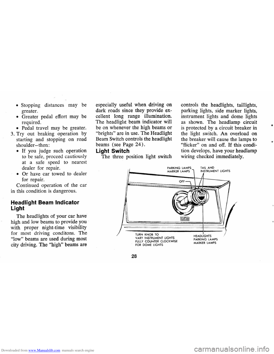
Light Switch
The three position light switch controls
the headlights, taillights,
parking lights, side marker lights,
instrument lights and dome lights
as shown. The headlamp circuit
is protected by a circuit breaker in
the light switch. An overload on
the breaker will cause the lamps to
"flicker" on and off. If this condi
tion develops, have your headlamp
wiring checked immediately.
PARKING LAMPS MARKER LAMPS TAIL AND INSTRUMENT LIGHTS
--,---.---~------ -- --------
TURN KNOB TO VARY INSTRUMENT LIGHTS fULLY COUNTER CLOCKWISE fOR DOME LIGHTS
28
HEADLIGHTS PARKING LAMPS MARKER LAMPS
•
Page 38 of 86
Downloaded from www.Manualslib.com manuals search engine Temperature (Lower Lever)
The temperature lever allows a
selection of air temperature from
Cold at the far left to Hot
at the far
right. When the temperature lever
is in the COLD position the system
will provide the coldest air possible.
When the temperature lever
is
moved to the right (toward HOT) ,
the system will operate on outside
air.
Selector (Upper Lever)
This lever provides a selection of
systems available to handle various
heating and cooling requirements
throughout the year. The Selector
lever has four
(4) major opera
tional
positions-"Off," "Air Condi
tioning," "Vent" and "Heating."
The "Air Conditioning" and "Heat
ing"
groups have several positions
which improve the effectiveness of the
system for various demands.
OFF-The system operates on low
blower regardless of fan switch po
sition with air discharged into
ve
hicle through heater outlet.
A/C-Air from the passenger com
partment
is recirculated through
the system with some outside air
and discharged from the upper out
lets when the temperature lever
is
in Full COLD or extreme left. If
the Temperature lever is moved
right to the first stop or further, the
system will automatically go on
outside air. The
AIC position, with
Temp. lever in Full
COLD, is used
when maximum cooling
is required
under conditions of high tempera
ture and humidity. High fan speed
is automatically attained in this
position .
36
A/C (with Temp lever right to first
stop) -Outside air
is passed
through the system and discharged
through the upper outlets. This po
sition
is recommended for most air
conditioning situations because of
reduced blower noise and reduction
of cigarette smdke within the
ve
hicle. Fan speed may be varied as
required.
VENT -Outside air is passed
through the system and discharged
from the upper and lower outlets.
This position
is provided for cool
to moderate weather when refrig
eration
is not required.
HEATER-Outside air
is delivered
through the heater outlet and with
some air through the defroster out
lets. Temperature may be adjusted
as required. This position is recom-