1971 CHEVROLET CAMARO key
[x] Cancel search: keyPage 6 of 88

Downloaded from www.Manualslib.com manuals search engine BEFORE DRIVING YOUR CAR
Keys
Two separate keys are provided
for your car. Each key has a differ
ent cross section
so that it can be
inserted only in certain locks.
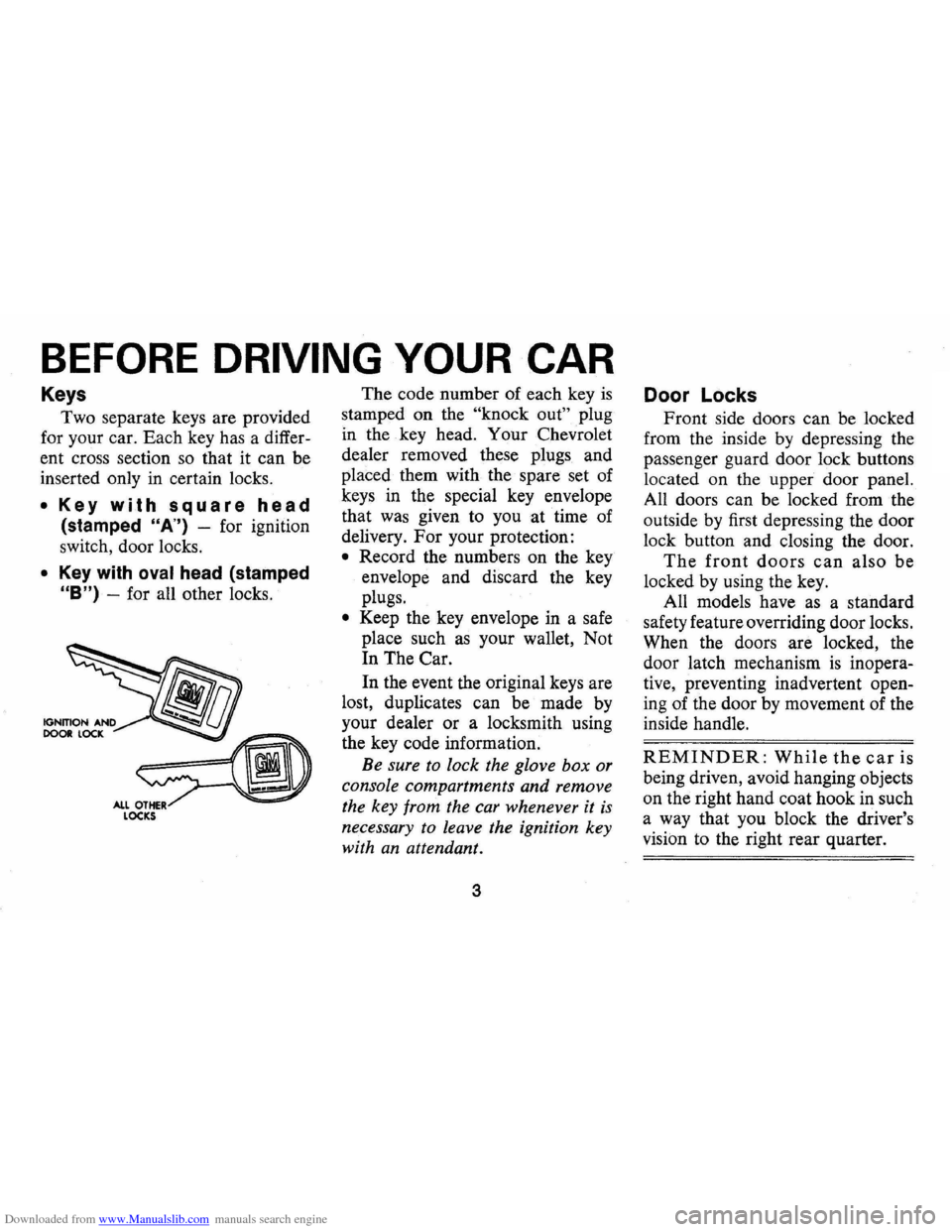
• Key with square head
(stamped "A") -for ignition
switch, door locks.
• Key with oval head (stamped
"B") -for all other locks. The
code number of each key
is
stamped on the "knock out" plug
in the key head. Your Chevrolet
dealer removed these plugs and
placed them with the spare set of
keys in the special key envelope
that was given to you at time of
delivery.
For your protection:
• Record the numbers on the key
envelope and discard the key
plugs.
• Keep the key envelope in a safe
place such
as your wallet, Not
In The Car.
In the event the original keys are
lost, duplicates can be made by
your dealer or a locksmith using
the key code information.
Be sure to lock the glove box or
console compartments and remove
the key from the car whenever it
is
necessary to leave the ignition key
with
an attendant.
3
Door Locks
Front side doors can be locked
from the inside by depressing the
passenger guard door lock buttons
located on the upper door panel.
All doors can be locked from the
outside by first depressing the door
lock button and closing the door.
The front doors can also be
locked by using the key.
All models have
as a standard
safety feature overriding door locks.
When the doors are locked, the
door latch mechanism
is inopera
tive, preventing inadvertent open
ing of the door by movement of the
inside handle.
REMINDER: While the car is
being driven, avoid hanging objects
on the right hand coat hook in such
a way that you block the driver's
vision to the right rear quarter.
Page 15 of 88

Downloaded from www.Manualslib.com manuals search engine STEERING COLUMN CONTROLS
Anti-Theft Steering
Column Lock
The anti-theft lock, located on the
right side of the steering column,
has
five positions:
• Accessory -Permits operation
of electrical accessories when
en
gine is not running. To engage,
push key in and
tum toward you
( counterclockwise) .
• Lock-Normal parking position.
Locks ignition and provides
added theft protection by pre
venting normal operation of
steering wheel and shift controls.
Key cannot be returned to
"lock"
position and removed until trans
mission is placed in "park"
(automatic transmission models)
or in reverse on manual
trans
mission models.
• Off-Permits turning engine off
without locking steering wheel
and shift controls.
12
• Run -Normal operating posi
tion.
• Start -Permits engagement of
starter.
NOTE: The anti-theft steering column lock is not a substitute lor the parking brake.
Always set the parking brake when leaving the car unaHended.
When parking-
• Always let go 01 steering wheel belore turning ignition key to lock position.
• When parking on a hill with wheels
turned toward curb, be sure car has
come to complete stop belore turning
key to lock position.
Turning wheels
after car has stopped "winds up" steering system, which can
result in a "spring back" 01 the steering
wheel when the steering column lock is
released. As a lurther precaution, never
reach through the steering wheel lor any
reason.
'"
When leaving your car unaHended, • Set parking brake. ·
• Place automatic transmission selector
in Park (Reverse tor manual transmission). . • Turn key to LOCK position. • Remove key (the buzzer will remind
you).
• Lock all doors.
Page 16 of 88

Downloaded from www.Manualslib.com manuals search engine Starting Engine
Automatic Transmission
Models
1. Apply the foot brake.
2. Place transmission selector
in "P" or "N" (UP" preferred).
A starter safety switch prevents
starter operation while the trans
mission selector
is in any drive
position.
(If it is necessary to
re-start the engine with the car
moving, place the selector lever
in
"N".)
3. Depress accelerator pedal and
activate starter
as outlined be
low for different conditions.
• Cold Engine -Fully de
press
accelerator pedal and
slowly release.
With foot off
the pedal,
crank the engine
by turning the ignition key
to the Start position-release
when engine starts.
If engine starts, but fails to
run, repeat this procedure.
When engine is running
smoothly, the idle speed may
be reduced by slightly de
pressing the accelerator pedal
and then slowly releasing.
• Warm Engine -Depress ac
celerator
pedal about halfway
and hold while cranking the
engine.
• Extremely Cold Weather
(Below
0° F.) Or After Car
Has Been Standing Idle
Several
Days-
Fully depress and release
accelerator pedal two
or three
times before cranking the
engine.
With foot off the ac
celerator pedal,
crank the
engine by turning the key to
the Start position and release
when engine starts.
13
Manual Transmission Models
1. Apply parking brake and shift
transmission to neutral.
2.
Hold clutch pedal to floor
throughout the starting proce
dure. A starter interlock pre
vents starter operation when
clutch
is not fully depressed.
3.
Operate accelerator pedal and
starter
as outlined in step 3
(under Automatic Transmission
Models).
Engine Flooded
Depress accelerator pedal and
hold to floor while starting until
engine
is cleared of excess fuel
and
is running smoothly. Never
"pump" the accelerator pedal.
Warm-Up
Always let the engine idle for
20 to 30 seconds after starting
and drive at moderate speeds for
several miles, especially during
cold weather.
Page 19 of 88

Downloaded from www.Manualslib.com manuals search engine Driving with Manual Transmissions
The 3-speed manual transmis
sion shift positions follow the
stan
dard pattern shown on the illustra
tion. The 4-speed transmission shift
lever, extending from the floor,has
its special shift pattern diagram
lo
cated on the knob or floor plate.
Depress the clutch pedal fully
be
fore attempting to shift to a differ
ent gear, then release the pedal to
move in that gear. Shifting into 2nd
and 3rd gear
as soon as possible
will add appreciably to your fuel
economy.
Both transmissions, being fully
synchronized, may be downshifted
into 1st gear at any speed below
20
m.p.h. Shift into Reverse gear only
after the car has stopped. Always depress
and release the clutch pedal
fully when shifting.
On Four-Speed
transmission the shift linkage may
be adjusted to allow
"short stroke"
shift lever operation. See your
Chevrolet Dealer.
Also, shift into
"Reverse" before
shutting
off engine. This will permit
the ignition key to be turned to the
"Lock" position.
REMINDER: Before descending a
steep or long grade, down a moun
tain or hillside, reduce speed and
shift into a lower gear (for either
automatic or manual transmission
cars).
Use the brakes sparingly to
prevent them from overheating and
thus reducing brake effectiveness.
16
Turn Signals and Lane
Change Feature
The turn signal lever is located
on the left side of the steering
col
umn immediately under the steer
ing wheel. The lever is moved up
ward to signal a right turn and '
downward to signal a left turn.
Lamps on the front and rear of the
car transmit this signal to other
Page 24 of 88

Downloaded from www.Manualslib.com manuals search engine Generator Indicator Light
This light provides a quick check
on the generating system of your
car. The red light will go on when
the ignition key
is in the "on" posi
tion, but before the engine is
started. After the engine starts, the
light should go out and remain out.
If the light remains on when engine
is running, have your Authorized
Chevrolet Dealer locate and correct
the trouble
as soon as possible.
Engine Temperature
Indicator Light
This indicator light is provided
in the instrument cluster to quickly
warn of an overheated engine. With
the ignition
switGh in the START
position, the red TEMP indicator
will light to let you know that it
is
operating properly.
When the engine
is started, the
red light will go out immediately.
It will light up at no other time
unless for some reason the engine
reaches a dangerously high
oper
ating temperature. If the red light
should come on, the engine must be
stopped until the cause of the
over
heating is corrected. Glance at in
strument cluster frequently as you
drive to see if this light
is on.
Brake System Warning
Light
The service brake system is de
signed so that half of the brake sys
tem will provide some braking ac
tion in the event of a hydraulic leak
in the other half of the system.
When the brake apply system
is not
operating properly, a warning light
located at lower left of instrument
cluster (speedometer face) will
glow continuously when the
igni
tion is on after the brakes have been
firmly applied.
On cars equipped
with drum brakes, the light will go
21
out when foot is removed from
brake pedal.
• As a check on bulb condition the
light should glow with the
park
ing brake applied and the igni
tion on. (Light is also a reminder
to release parking brake.)
• Have system repaired if light
does not come on during check.
• This warning light is nota sub
stitute for the visual check of
brake fluid level required
as part
of normal maintenance.
If the light glows red:
• The parking brake is not fully re
leased or,
• The service brake system is par
tially inoperative.
What to do:
1. Check that the parking brake is
released.
2. Pull off the road and stop, care
fully-remembering that:
Page 39 of 88

Downloaded from www.Manualslib.com manuals search engine For further details on the engine and transmission
items listed on the
"Vehicle Safety Maintenance
Schedule," and for other recommended maintenance,
refer
to the "Service and Maintenance" and "Air
Pollution. Control" Sections of this manual.
CHECKS lOBE PERFORMED
BY OWNER
Listed below are the safety checks that should be
made by the owner . These checks should be made at
least every 4 months or
6,000 miles, whichever occurs
first , or more often when so indicated . Any
deficien
cies should be brought to the attention of your dealer
or service station, so the advice of a qualified mech
anic is available regarding the need for repairs or
replacements.
• Anti-Theft Lock-Check for proper operation by
attempting to turn key to
LOCK position in the
various transmission gears with
car stationary. Key
should
tum to LOCK position only when trans
mission control is in PARK on automatic trans
mission models or in REVERSE on manual trans
mission models.
• Seat Belts-Check lap and shoulder belts as well
as buckles, retractors and anchors for loose con-
36
nections, damage and positive latching action.
• Windshield Wipers and Washers-Check con
dition and alignment of wiper blades. Check
amount and direction of fluid sprayed by washers
during use.
• Defrosters-Check performance by turning con
trols to "de-ice" and "Hi" fan speed and noting
amount of air directed against the windshield.
• Wheel Alignment and Balance-In addition to
abnormal tire wear the need for wheel alignment
service may be indicated by a pull to the right or
left when driving on a straight level road. The need
for wheel balancing may be indicated by a
vibra
tion at the steering wheel while driving.
• Parking Brake and "Park" Mechanism-Check
parking brake holding ability by parking on a fairly
steep hill and restraining the vehicle with the
parking brake only.
On cars with automatic trans
missions, check the holding ability of the "Park"
mechanism by releasing all brakes after the trans
mission selector lever has been placed in the "P"
position.
• Lights -Check license plate lights, side marker
lights , headlamps, parking lamps, tail lamps , brake
Page 48 of 88

Downloaded from www.Manualslib.com manuals search engine AIR INJECTION REACTOR (AIR)
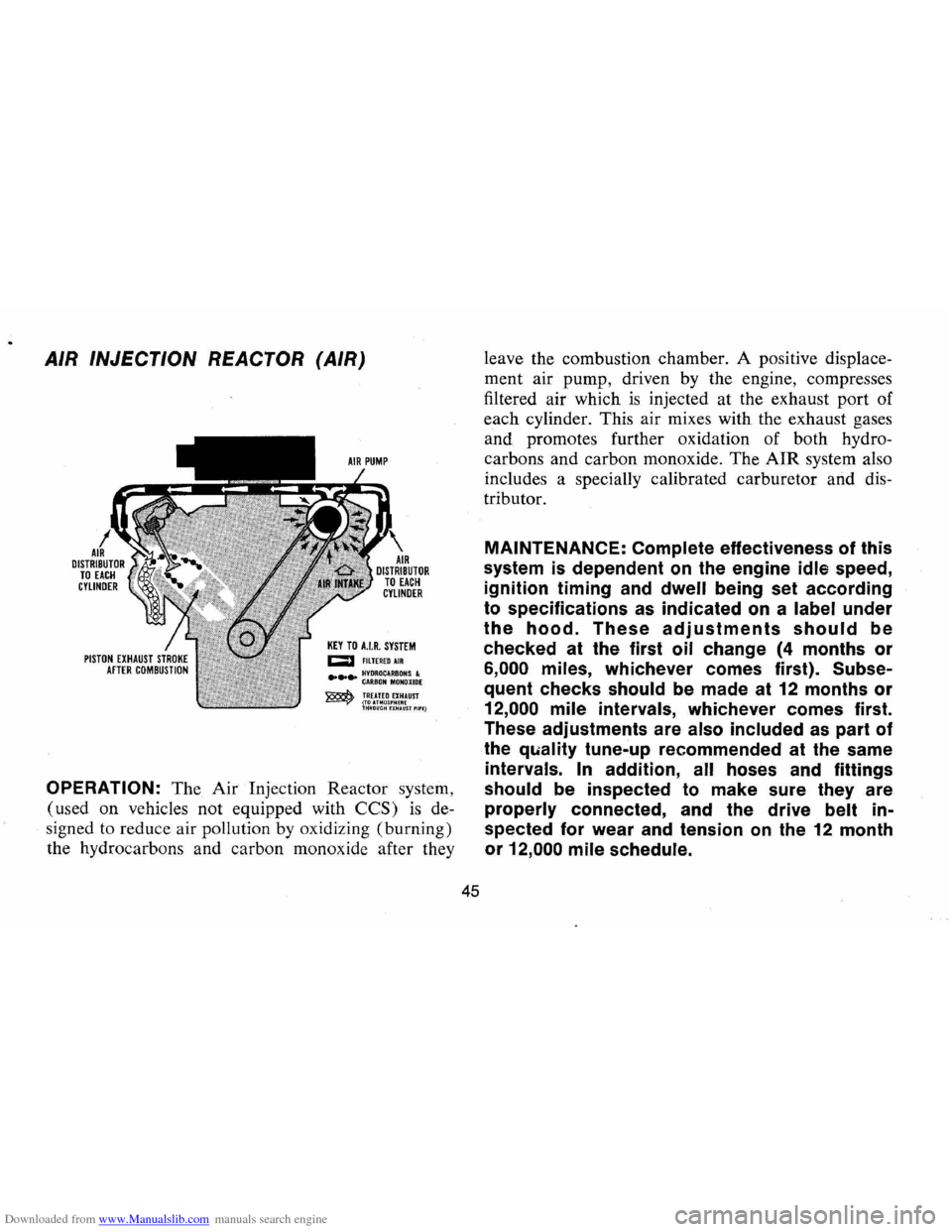
KEY TO HR. SYSTEM CJ F1LTEREDAIR
.... ~!~:~~A:~~~~I:E ~ TREATED EXHAUST ~(TOUMOS'HERE THMOUGHHHAlIST'II'E)
OPERATION: The Air Injection Reactor system,
(used on vehicles not equipped with
CCS) is de
signed to reduce air pollution by oxidizing (burning)
the hydrocarbons and carbon monoxide after they
45
leave the combustion chamber. A positive displace
ment air pump, driven by the engine, compresses
filtered air which
is injected at the exhaust port of
each cylinder. This air mixes with the exhaust gases
and promotes further oxidation of both hydro
carbons and carbon monoxide. The
AIR system also
includes a specially calibrated carburetor and dis
tributor.
MAINTENANCE: Complete effectiveness of this
system
is dependent on the engine idle speed,
ignition timing and
dwell being set according
to specifications as indicated on a label under
the hood. These adjustments should be
checked at the first oil change (4 months or
6,000 miles, whichever comes first). Subse
quent checks should be made at 12 months or
12,000 mile intervals, whichever comes first.
These adjustments are
also included as part of
the
quality tune-up recommended at the same
intervals. In addition, all hoses and fittings
should be inspected to make sure they are
properly connected, and the drive belt in
spected for wear
and tension on the 12 month
or
12,000 mile schedule.
Page 73 of 88

Downloaded from www.Manualslib.com manuals search engine (E) If the car will start but stalls when hot or has a rough idle, you can suspect a faulty IDLE ADJUSTMENT, a malfunctioning AUTOMATIC CHOKE or an extremely dirty and blocked AIR CLEANER ELEMENT. Replace paper element air cleaner if necessary. Idle adjustment or automatic choke service (other than that outlined in paragraph D above) should be performed by your Chevrolet Dealer.
If the above Fuel System checks and the checks suggested under the Electrical System following do not correct the malfunction, it is recommended that you return to your Authorized Chevrolet Dealer for further checks, adjustments or repairs.
ELECTRICAL SYSTEM
If, when the ignition key is turned to "Start", the engine will not
turn over, you have good reason to suspect electrical trouble.
NOTE: Never remove Delcotron bat lead without first disconnecting battery ground cable.
(F) When there is no response at all to attempts to start the car, check the obvious-your AUTOMATIC TRANSMISSION SELECTOR LEVER must be in Neutral or Park position before the engine can be started. Turning the IGNITION SWITCH rapidly back and forth several times will sometimes correct a poor internal switch contact.
(G) The BATIERY may be discharged. If so, lights will be dim and the horn will have a poor tone if it will blow at all.
Usually
a garage recharge will be necessary to return the battery to operation. Occasionally, however, a long drive will recharge the battery.
NOTE: If the battery is determined to be dead, and for no apparent reason, have your Authorized Chevrolet Dealer check the
battery, the GENERATOR and the VOLTAGE REGULATOR. GENERATOR trouble should already have been indicated by the gene~ator indicator light on the instrument panel.
70
POOR BATIERY CONNECTIONS may be suspected if the car has operated properly a short time before and now not even the horn will operate. Check both ends of both battery cables. If the con
nections are corroded, a car may sometimes be restored to operation by removing all cable ends, scraping all contacting surfaces clean with a pen knife, and reassembling. If the cables are broken,
they must be replaced. The power supply should now be restored unless the battery is dead.
(H) If, however, the lights and horn work properly but the starter will still not turn over, check the STARTER connections. A "click" from the starter solenoid indicates that the wiring to the starter is properly installed. If the wiring seems to be clean and tightly installed, the trouble is probably in the starter itself and should be referred to your Authorized Chevrolet Dealer.
When the engine will "turn over" but will not start, the following items may be checked along with the Fuel Systems Checks listed
previously.
(I) With a clean dry cloth, wipe the ceramic portions of the spark plugs dry. In particularly damp or rainy weather dampness may be the cause of not starting, especially when the engine is cold.
(J) Check the cables at the top of the distributor and coil as well as each spark plug cable for tightness.
(K) If the car will still not start, check for spark at the spark plugs in the following manner:
Pull one of the spark plug wires off its spark plug. Insert a
short piece of bare wire (such as Distributor and Coil Cables