1971 CHEVROLET CAMARO battery
[x] Cancel search: batteryPage 20 of 88
Downloaded from www.Manualslib.com manuals search engine motorists and pedestrians. The ig
nition switch must be in the "ON"
position in order for the turn sig
nals to be operational. This feature
prevents battery drain if the lever
is left in an "ON" position when
your car
is not in use.
In a normal turning situation
such
as turning a corner, the turn
signal is cancelled automatically
after the turn
is completed. How
ever, in some driving maneuvers
such
as changing lanes on an ex
pressway, the steering wheel
is not
turned back sufficiently after com
pleting the turn to automatically
cancel the turn signal. For con
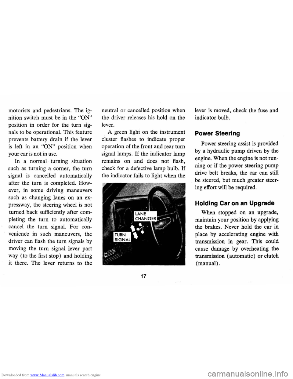
venience in such maneuvers, the
driver can flash the turn signals by
moving the turn signal lever part
way (to the first stop) and holding
it there. The lever returns to the neutral
or cancelled position when
the driver releases his hold on the
lever.
A green light on the instrument
cluster flashes to indicate proper
operation of the front and rear
tum
signal lamps. If the indicator lamp
remains on and does not flash,
check for a defective lamp bulb.
If
the indicator fails to light when the
17
lever is moved, check the fuse and
indicator bulb.
Power Steering
Power steering assist is provided
by a hydraulic pump driven by the
engine. When the engine
is not run
ning
or if the power steering pump
drive belt breaks, the car can still
be steered, but much greater steer
ing effort will be required.
Holding Car on an Upgrade
When stopped on an upgrade,
maintain your position by applying
the brakes. Never hold the car in
place by accelerating engine with
transmission in gear. This could
cause damage by overheating the
transmission (automatic) or clutch
(manual).
Page 26 of 88
Downloaded from www.Manualslib.com manuals search engine kJ
2530 35404550
15 55
10 60
5 65 RPM/IOO 70 llllD
Optional Instruments and Gauges
Tachometer and Oil Pressure Indicator Light
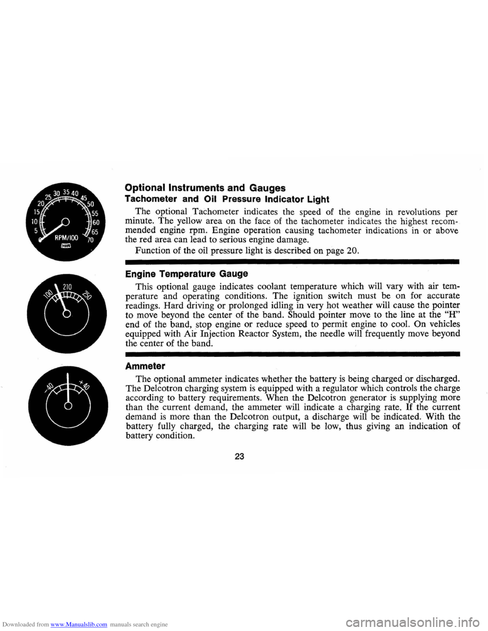
The optional Tachometer indicates the speed of the engine in revolutions per
minute.
The yellow area on the face of the tachometer indicates the highest recom
mended engine rpm. Engine operation causing tachometer indications in or above
the red area can lead to serious engine damage.
Function of the oil pressure light is described on page
20.
Engine Temperature Gauge
This optional gauge indicates coolant temperature which will vary with air tem
perature and operating conditions. The ignition switch must be on for accurate
readings. Hard driving
or prolonged idling in very hot weather will cause the pointer
to move beyond the center of the band.
Should pointer move to the line at the "H"
end of the band, stop engine or reduce speed to permit engine to cool. On vehicles
equipped with Air Injection Reactor System, the needle will frequently move beyond
the center of the band.
Ammeter
The optional ammeter indicates whether the battery is being charged or discharged.
The Delcotron charging system is equipped with a regulator which controls the charge
according to battery requirements. When the Delcotron generator
is supplying more
than the current demand, the ammeter will indicate a charging rate.
If the current
demand
is more than the Delcotron output, a discharge will be indicated. With the
battery fully charged, the charging rate will be low, thus giving an indication of
battery condition.
23
Page 42 of 88
Downloaded from www.Manualslib.com manuals search engine • To. start the car when the Ener
gizer (battery)
is discharged,
use a single auxiliary battery
Qr
Energizer Qf the same vQltage as
the discharged battery, with suit
able jumper cables.
• Make cQnnectiQns detailed as
fQllQws:
Jump Starting with
Auxiliary (Booster) Battery
If booster battery is part Qf an
Qther vehicle's electrical system,
bQQster shQuld be treated carefully
when using jumper cables.
FQllQW
exactly the prQcedure Qutlined be
IQw, being careful nQt to. cause
sparks:
1. Set parking brake and place
autQmatic transmissiQn in
"PARK" ("NEUTRAL" fQr
manual transmissiQn).
2. Attach
Qne end of Qne jumper
cable
to. the PQsitive terminal Qf
the booster battery (identified by
"+" or "P" Qn the battery case,
PQst Qr clamp) and the Qther end
Qf same cable to. PQsitive ter
minal
Qf discharged battery.
3. Attach ene end ef the remain
ing cable
to. negative terminal
("-" er "N") ef booster battery,
and finally to. negative terminal
ef discharged battery -taking
i;cAufICsN}R.4btAl0W,CAP '!":;',';"S"!<"" .
···.···.T~·p,.v~ttt.,0 •• ot~~()l.nf.·#rii·j~6Itl t"~
'd.nger of being '. bu'n.d,~oo/.ntl.v.' .houldb.'ch.cked,.ndcoo/.nt .dd.4. only wh.n the .nglne/. cool.
'.Donot r.IJJov.radl.tbic.p whlj."'gln~ .ndradl.to,are.tlll hot, b.c.u ••. the
. cooling sVst.", will blow 'out .c.,dlng , fluid .nd st"m und.r pr.ssur ••
,
tol.mov. b"pWh.riengln./s
39
care that jumper clamps do. nQt
CQntact each ether,
Reverse this sequence exactly
when remeving the jumper cables.
CAUTION: Any proc~ur.~th.rt".n the'
.bove could r •• ult In person.' In/ury c.us.d by electrolyte .qulrtlng out .th. b.tt.ryvent., d.m.g. or In/ury due to b.tt.ry .xplo./on .ndlor d.m.g. to the charging sy.t.m of the boost., v.hlc/,'; or Immoblllz.d . v.hlcl.'. chargIng 'Y'tem. Do not .ttempt to lump .tart a c.r havIng • frozen battery b.cau •• the bit
t.ry mlY .xplod.. It • froz.n b.ttery I. su.pect.d, op.n .nd .x.mln •• 11 fill v.nt. , on the b.ttery. If Ie. c.n b •.. en, or the .,.ctrolyt. fluid c.nnotb •••• n, do not
att.mpt to .tart with /um".r c.bl ...
.'. $Iow~y ,otat • . c.p . count.rC/ockwl'~ .iQ ; d.terit(DO NOT PRESS DOWN WHILE
ROTATING).
•. Walt unt/f.ny ,e.ldu.' pressure I.re' lI.v.d-•• Indlc.t.d by • hissIng .ound.
• p,.ss down on c.p whll. continuing to rot.te counterclockwise.
Radl.tor pre.,ure cap. should b. check.d by • quallfl.d m.chanlc p.rlodlcally for proper op.ratlon and replaced .s r .. qulr.d with the .pplicabl.AC typ •.
Page 67 of 88
Downloaded from www.Manualslib.com manuals search engine 3. Cold tire inflation pressure:
after vehicle has been inopera
tive for 3 hours
or more, or
driven less than 1 mile. Hot tire
inflation pressure:
after vehicle
has been driven
10 miles or at
speeds of more than
60 miles
per hour.
4. Vehicles with luggage racks do
not have a vehicle load limit
greater than specified.
5. When towing trailers, the allow
able passenger and cargo load
must be reduced by
an amount
equal to the trailer tongue load
on the trailer hitch.
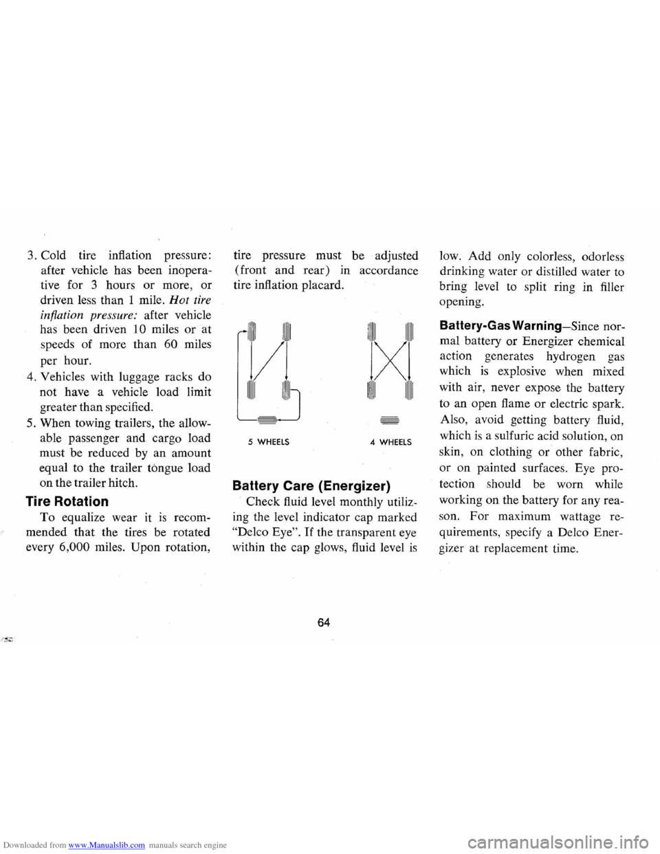
Tire Rotation
To equalize wear It IS recom
mended that the tires be rotated
every
6,000 miles. Upon rotation, tire
pressure must be adjusted
(front
and rear) in accordance
tire inflation placard.
1IIII1 1IIII1
/
IIIIII IIIIIJ
1IIII1 111111
IXl
1IIII1 111111
5 WHEELS 4 WHEELS
Battery Care (Energizer)
Check fluid level monthly utiliz
ing the level indicator cap marked
"Delco Eye". If the transparent eye
within the cap glows, fluid level
is
64
low. Add only colorless, odorless
drinking water
or distilled water to
bring level to split ring in filler
opening.
Battery-Gas Warning-Since nor
mal battery
or Energizer chemical
action generates hydrogen gas
which
is explosive when mixed
with air, never expose the battery
to an open flame
or electric spark.
Also, avoid getting battery fluid,
which
is a sulfuric acid solution, on
skin, on clothing
or other fabric,
or on painted surfaces. Eye pro
tection should be worn while
working on the battery for any rea
son.
For maximum wattage re
quirements, specify a Delco Ener
gizer at replacement time.
Page 69 of 88
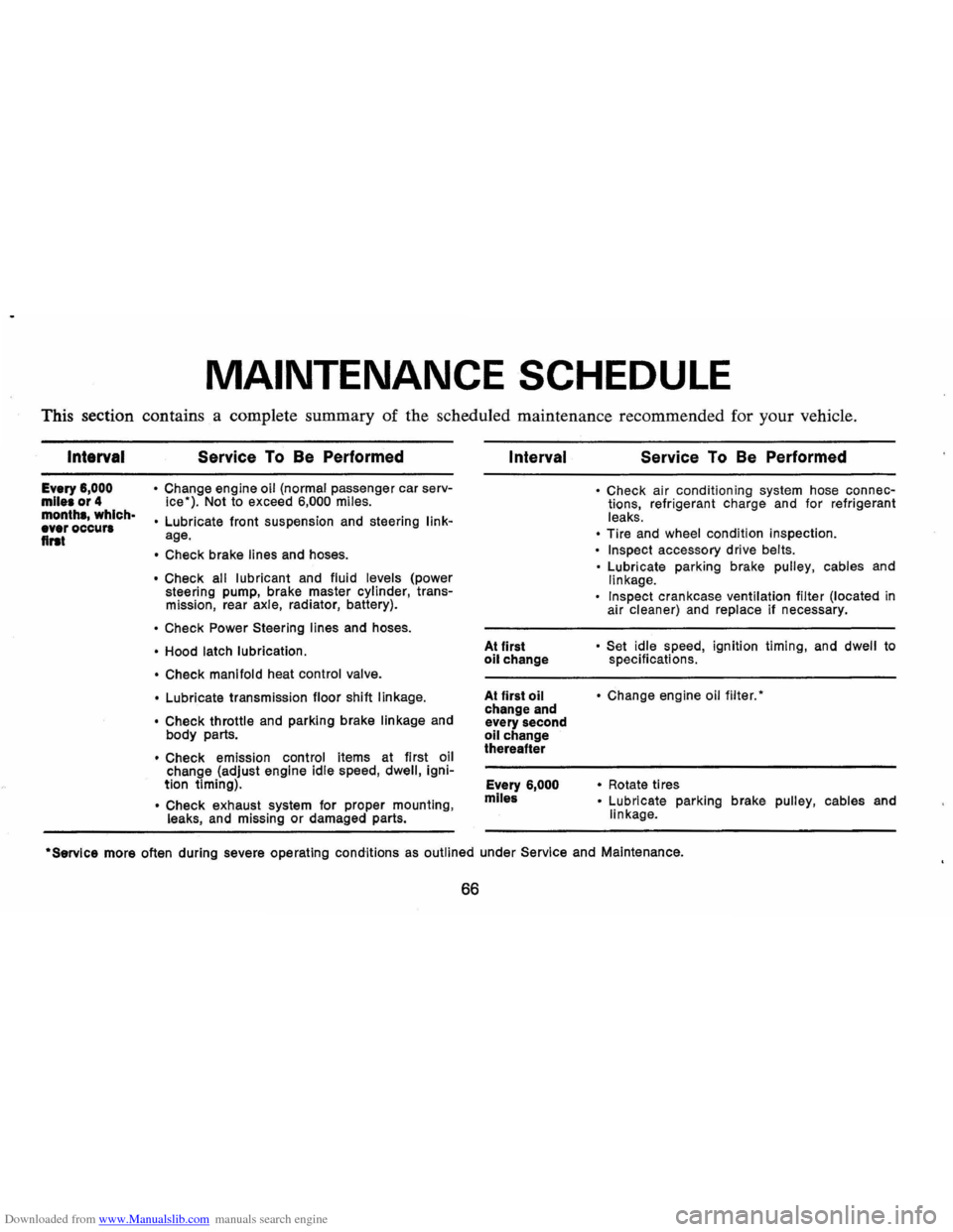
Downloaded from www.Manualslib.com manuals search engine MAINTENANCE SCHEDULE
This section contains a complete summary of the scheduled maintenance recommended for your vehicle.
Intarval
Every 6,000 mile. or 4 month., which· ever occur. flrat
Service To Be Performed
• Change engine oil (normal passenger car serv
ice"). Not to exceed 6,000 miles.
•
Lubricate front suspension and steering linkage.
• Check brake lines and hoses.
• Check all lubricant and fluid levels (power
steering pump, brake master cylinder, transmission, rear axle, radiator, battery).
• Check Power Steering lines and hoses.
• Hood latch lubrication.
• Check manifold
heat control valve.
•
Lubricate transmission floor shift linkage.
• Check
throttle and parking brake linkage and
body parts.
• Check emission control items at first oil
change (adjust engine idle speed, dwell, ignition timing) .
• Check exhaust system for proper mounting , leaks, and missing or damaged parts.
Interval
At first oil change
At first
oil change and
every second
oil change
thereafter
Every
6,000
mlle&
Service To Be Performed
• Check air conditioning system hose connections, refrigerant charge and for refrigerant
leaks.
• Tire and wheel condition inspection.
• Inspect accessory drive belts.
•
Lubricate parking brake pulley, cables and linkage.
Inspect crankcase ventilation filter (located in
air cleaner) and replace if necessary.
• Set idle speed , ignition timing, and dwell to
specifications.
• Change engine oil filter."
•
Rotate ti res • Lubricate parking brake pulley, cables and
linkage .
·Servlce more often during severe operating conditions as outlined under Service and Maintenance.
66
Page 70 of 88

Downloaded from www.Manualslib.com manuals search engine Interval
First 12,000 miles Every 12
months
or 12,000 miles
Every
24,000 miles
Service To Be Performed
• Rotate distributor cam lubricator. See 24,000 mile recommendation.
• Insp .ect air cleaner element, if satisfactory
rotate 1800 from original position and reinstall. See 24,000 mile recommendation.
• Inspect brake linings and check system for
leaks
• Inspect parking brake and throttle linkage. • Engine tune-up.
Replace carburetor 'Inlet fuel filter element. • Check emission control items. • Inspect AIR drive belt.
Evaporation Control System-Replace filter in
base of canister and inspect canister. • Check headlamp aiming.
• Repack front wheel bearings.
• Replace distributor cam lubricator. • Drain automatic transmission sump and add
fresh fluid (normal passenger car service).' Adjust Powerglide low band at first fluid
change.
• Replace crankcase ventilation filter (located
within air cleaner).
• Replace Turbo Hydra-Matic sump filter.
Interval Service To Be Performed
Every 2 years • Drain radiator coolant, flush and refill system.
Every
24 months· Replace PCV Valve. Inspect all hoses and or 24,(100 miles fittings.
Every
36,000 • Check steering gear for seal leakage (actual
miles solid grease-not just oily film).
• Lubricate clutch cross shaft (sooner if necessary), remove plug and install lube fittIng.
During Winter
• Check operation of air conditioning system.
months
Periodically • Check battery liquid leve/.
• Inspect seat belts, buckles, retractors and
anchors.
• Check all lights for proper operation.
As Required
• Check wheel alignment and balancing.
'Service more often during severe operating conditions as outlined under Service and Maintenance.
67
Page 73 of 88

Downloaded from www.Manualslib.com manuals search engine (E) If the car will start but stalls when hot or has a rough idle, you can suspect a faulty IDLE ADJUSTMENT, a malfunctioning AUTOMATIC CHOKE or an extremely dirty and blocked AIR CLEANER ELEMENT. Replace paper element air cleaner if necessary. Idle adjustment or automatic choke service (other than that outlined in paragraph D above) should be performed by your Chevrolet Dealer.
If the above Fuel System checks and the checks suggested under the Electrical System following do not correct the malfunction, it is recommended that you return to your Authorized Chevrolet Dealer for further checks, adjustments or repairs.
ELECTRICAL SYSTEM
If, when the ignition key is turned to "Start", the engine will not
turn over, you have good reason to suspect electrical trouble.
NOTE: Never remove Delcotron bat lead without first disconnecting battery ground cable.
(F) When there is no response at all to attempts to start the car, check the obvious-your AUTOMATIC TRANSMISSION SELECTOR LEVER must be in Neutral or Park position before the engine can be started. Turning the IGNITION SWITCH rapidly back and forth several times will sometimes correct a poor internal switch contact.
(G) The BATIERY may be discharged. If so, lights will be dim and the horn will have a poor tone if it will blow at all.
Usually
a garage recharge will be necessary to return the battery to operation. Occasionally, however, a long drive will recharge the battery.
NOTE: If the battery is determined to be dead, and for no apparent reason, have your Authorized Chevrolet Dealer check the
battery, the GENERATOR and the VOLTAGE REGULATOR. GENERATOR trouble should already have been indicated by the gene~ator indicator light on the instrument panel.
70
POOR BATIERY CONNECTIONS may be suspected if the car has operated properly a short time before and now not even the horn will operate. Check both ends of both battery cables. If the con
nections are corroded, a car may sometimes be restored to operation by removing all cable ends, scraping all contacting surfaces clean with a pen knife, and reassembling. If the cables are broken,
they must be replaced. The power supply should now be restored unless the battery is dead.
(H) If, however, the lights and horn work properly but the starter will still not turn over, check the STARTER connections. A "click" from the starter solenoid indicates that the wiring to the starter is properly installed. If the wiring seems to be clean and tightly installed, the trouble is probably in the starter itself and should be referred to your Authorized Chevrolet Dealer.
When the engine will "turn over" but will not start, the following items may be checked along with the Fuel Systems Checks listed
previously.
(I) With a clean dry cloth, wipe the ceramic portions of the spark plugs dry. In particularly damp or rainy weather dampness may be the cause of not starting, especially when the engine is cold.
(J) Check the cables at the top of the distributor and coil as well as each spark plug cable for tightness.
(K) If the car will still not start, check for spark at the spark plugs in the following manner:
Pull one of the spark plug wires off its spark plug. Insert a
short piece of bare wire (such as Distributor and Coil Cables
Page 75 of 88

Downloaded from www.Manualslib.com manuals search engine SPECIFICATIONS
VEHICLE IDENTIFICATION NUMBER
Car-Stamped on Vehicle Identification Plate attached to left
of instrument panel.
Engine-Stamped on boss on block.
6-Cylinder-On right side of block to rear of distributor.
S-Cylinder-On right side of block at front.
Body-Stamped on plate attached to cowl panel.
DIMENSIONS
Overall Length (Coupe) ....................... 18S.0"
Height ..................................... 50.5"
Width .................................... 74.4"
Wheelbase ................................ 108.0"
72
BATTERY RATING
L6 engine equipped vehicles-12 volt, 54 plate, 2300 watts'
350 and 402 VS engine equipped vehicles-12 volt, 66 plate,
2900 watts'
Heavy Duty-12 volt, 90 plate, 3750 watts'
'Cranking power at O°F.
CAPACITIES
Gasoline Tank
(Approx.)
Crankcase
(Refill)
6 and S Cylinder
Oil change only
u.s. Measure
17.0 gal.
4 qt.
Oil and Filter change . . . . . . .. 5 qt.
Imperial Measure
14.25 gal.
3% qt.
4 % qt.