1971 CHEVROLET CAMARO check engine
[x] Cancel search: check enginePage 4 of 88

Downloaded from www.Manualslib.com manuals search engine 1971 CAMARO
OWNER'S
MANUAL
CHEVROLET MOTOR
DIVISION
GENERAL MOTORS
CORPORATION DETROIT, MICHIGAN 48202
All information, illustrations and specifications
contained in this manual are based on the latest product
information available at the time of publication. The right is reserved to make changes at any time without
notice.
Part No. 3991061
ST 309-71
©GENERAL MOTORS CORPORATION 1970
Table of Contents Page
Before Driving your Car. _ ...... _ . . . . . . . . . . . . . . . . . . . . . . . . . . . . . . . . . 3
Starting and Operating
............................................ 11
Safety Checks. . . . . . . . . . . . . . . . . . . . . . . . . . • . . . . . . . . . . . . . . . . . . . . . . .. 33
In Case of Emergency. . . . . . . . . . . . . . . . . . . . . . . . . . . . . . . . . . . . . . . . . . .. 38
Air
Pollution Control Systems.. .. . ....... . . . . .. . .. .. .. . .. . .. .. . ... 41
Appearance Care. . . . . . . . . . . . . . . . . . . . . . . . . . . . . . . . . . . . . . . . . . . . . . . .. 47
Service and Maintenance ......................................... 51
Maintenance Schedule ........................................... 66
Specifications,
Owner Relations, Service Manuals, Index ........... 72
1
Page 10 of 88

Downloaded from www.Manualslib.com manuals search engine tion against impact with the car in
terior
by restraining forward mo
tion of the upper torso in a colli
sion. This
is primarily true in case
of frontal impacts, which are the
most frequent type of accident. Shoulder
belts are fastened and
unfastened in the same manner
as
lap belts. A shoulder belt should
have sufficient slack to insert a fist's
width between your chest and the
belt. This can be checked by insert
ing a clenched
fist between the belt
and your chest with thumb against
chest and back of hand facing up
ward.
Releasing Belts -To release the
belts, simply depress the release tab
or button located
in the center of
the buckle.
7
Seat Belt Inspection
And Care (All)
• Keep sharp edges and damaging
objects away from belts.
• Periodically inspect belts,
buckles, retractors, and anchors
for damage that could lessen the
effectiveness of the restraint
system.
• Have questionable parts re
placed.
• Replace belts if cut, weakened,
frayed,
or subjected to collision
loads.
• Check that anchor mounting
bolts are tight to the floor.
• Keep seat belts clean and dry.
• Clean only with mild soap solu
tion and lukewarm water.
• Do not bleach or dye belts since
this may severely weaken belts.
Page 13 of 88

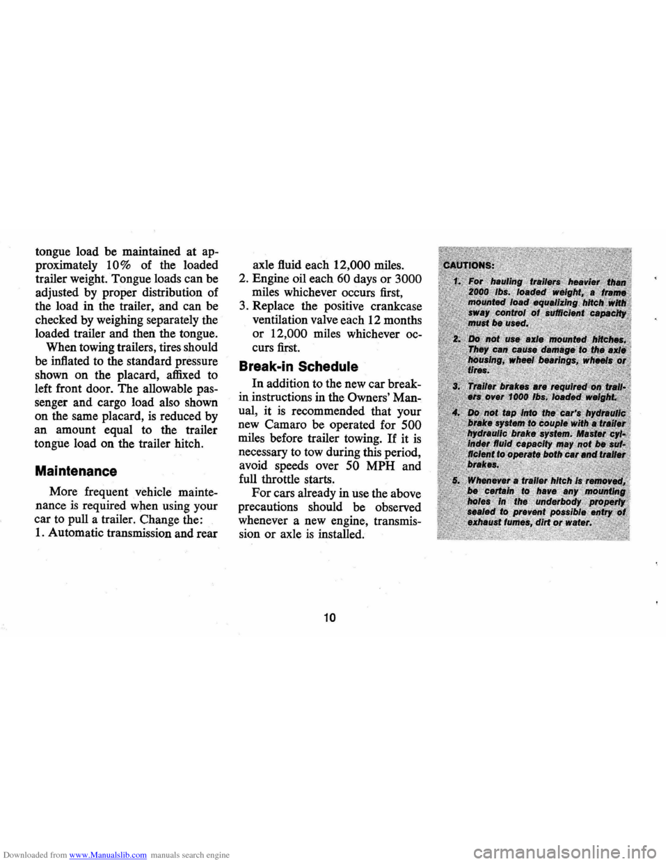
Downloaded from www.Manualslib.com manuals search engine tongue load be maintained at ap
proximately
10% of the loaded
trailer weight. Tongue loads can be
adjusted by proper distribution of
the load in the trailer, and can be
checked by weighing separately the
loaded trailer and then the tongue.
When towing trailers, tires should
be inflated to the standard pressure
shown
on the placard, affixed to
left front door. The allowable pas
senger and cargo load also shown
on the same placard,
is reduced by
an amount equal to the trailer
tongue load on the trailer hitch.
Maintenance
More frequent vehicle mainte
nance
is required when using your
car to pull a trailer. Change the:
1. Automatic transmission and rear axle
fluid each
12,000 miles.
2. Engine oil each
60 days or 3000
miles whichever occurs first,
3. Replace the positive crankcase
ventilation valve each 12 months
or 12,000 miles whichever oc
curs first.
Break .. in Schedule
In addition to the new car break
in instructions in the
Owners' Man
ual,
it is recommended that your
new Camaro be operated for
500
miles before trailer towing. If it is
necessary to tow during this period,
avoid speeds over
50 MPH and
full throttle starts.
For cars already in use the above
precautions should be observed
whenever a new engine, transmis
sion
or axle is installed.
10
Page 20 of 88

Downloaded from www.Manualslib.com manuals search engine motorists and pedestrians. The ig
nition switch must be in the "ON"
position in order for the turn sig
nals to be operational. This feature
prevents battery drain if the lever
is left in an "ON" position when
your car
is not in use.
In a normal turning situation
such
as turning a corner, the turn
signal is cancelled automatically
after the turn
is completed. How
ever, in some driving maneuvers
such
as changing lanes on an ex
pressway, the steering wheel
is not
turned back sufficiently after com
pleting the turn to automatically
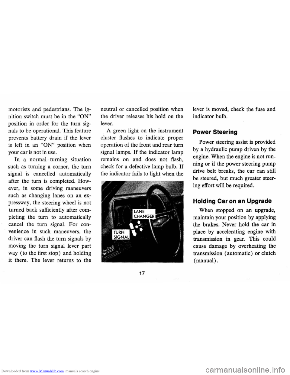
cancel the turn signal. For con
venience in such maneuvers, the
driver can flash the turn signals by
moving the turn signal lever part
way (to the first stop) and holding
it there. The lever returns to the neutral
or cancelled position when
the driver releases his hold on the
lever.
A green light on the instrument
cluster flashes to indicate proper
operation of the front and rear
tum
signal lamps. If the indicator lamp
remains on and does not flash,
check for a defective lamp bulb.
If
the indicator fails to light when the
17
lever is moved, check the fuse and
indicator bulb.
Power Steering
Power steering assist is provided
by a hydraulic pump driven by the
engine. When the engine
is not run
ning
or if the power steering pump
drive belt breaks, the car can still
be steered, but much greater steer
ing effort will be required.
Holding Car on an Upgrade
When stopped on an upgrade,
maintain your position by applying
the brakes. Never hold the car in
place by accelerating engine with
transmission in gear. This could
cause damage by overheating the
transmission (automatic) or clutch
(manual).
Page 24 of 88

Downloaded from www.Manualslib.com manuals search engine Generator Indicator Light
This light provides a quick check
on the generating system of your
car. The red light will go on when
the ignition key
is in the "on" posi
tion, but before the engine is
started. After the engine starts, the
light should go out and remain out.
If the light remains on when engine
is running, have your Authorized
Chevrolet Dealer locate and correct
the trouble
as soon as possible.
Engine Temperature
Indicator Light
This indicator light is provided
in the instrument cluster to quickly
warn of an overheated engine. With
the ignition
switGh in the START
position, the red TEMP indicator
will light to let you know that it
is
operating properly.
When the engine
is started, the
red light will go out immediately.
It will light up at no other time
unless for some reason the engine
reaches a dangerously high
oper
ating temperature. If the red light
should come on, the engine must be
stopped until the cause of the
over
heating is corrected. Glance at in
strument cluster frequently as you
drive to see if this light
is on.
Brake System Warning
Light
The service brake system is de
signed so that half of the brake sys
tem will provide some braking ac
tion in the event of a hydraulic leak
in the other half of the system.
When the brake apply system
is not
operating properly, a warning light
located at lower left of instrument
cluster (speedometer face) will
glow continuously when the
igni
tion is on after the brakes have been
firmly applied.
On cars equipped
with drum brakes, the light will go
21
out when foot is removed from
brake pedal.
• As a check on bulb condition the
light should glow with the
park
ing brake applied and the igni
tion on. (Light is also a reminder
to release parking brake.)
• Have system repaired if light
does not come on during check.
• This warning light is nota sub
stitute for the visual check of
brake fluid level required
as part
of normal maintenance.
If the light glows red:
• The parking brake is not fully re
leased or,
• The service brake system is par
tially inoperative.
What to do:
1. Check that the parking brake is
released.
2. Pull off the road and stop, care
fully-remembering that:
Page 25 of 88

Downloaded from www.Manualslib.com manuals search engine • Stopping distances may be
greater.
• Greater pedal et!ort may be re
quired.
• Pedal travel may be greater.
3. Try out
brak~ operation by
starting and stopping on road
shoulder-then:
• If you judge such operation to be
safe, proceed cautiously at re
duced speed to nearest dealer for
repair.
• Have car towed to dealer for re
pair.
• Continued operation of the car
in this condition
is dangerous.
Headlight Beam Indicator
Light
The headlights of your car have
high and low beams to provide you with
proper night-time visibility
during all driving conditions.
The
"low" beams are used during most
city driving. The
"high" beams are
especially useful when driving on
dark roads since they provide ex
cellent long range illumination.
The headlight beam indicator will
be on whenever the
high beams or
"brights" are in use. The Headlight
Beam Switch controls the headlight
beams (see
Page 32).
Light Switch
The three position light switch
controls the headlights, taillights,
parking lights, side marker lights,
instrument lights and dome lights
as shown. The headlamp circuit is
protected by a circuit breaker in the
light switch.
An overload on the
breaker will cause the lamps to
"flicker" on and ot!. If this condi
tion develops, have your headlamp
wiring checked immediately.
PARKING LAMPS MARKER LAMPS TAIL AND INSTRUMENT
LIGHTS
TURN KNOB TO
VARY INSTRUMENT LIGHTS fULLY COUNTER CLOCKWISE FOR DOME LIGHTS
22
HEADLIGHTS PARKING LAMPS MARKER LAMPS
Page 27 of 88

Downloaded from www.Manualslib.com manuals search engine Clock
Reset the clock, if your car is so
equipped, by pulling out the knob
and turning the hands clockwise
if
slow, counterclockwise if fast. This
will, if the clock error
is five min
utes
or more, automatically com
pensate for time gain or lag.
Sev
eral resettings, several days apart,
may be needed to properly adjust
the clock mechanism. Have your
clock cleaned and oiled by a com
petent clock serviceman at least
every two years.
Cigarette Lighter
The accessory cigarette lighter is
located on the instrument panel
face. To operate, push it in. When
it becomes heated, it automatically
pops out ready for
use.
Windshield Wiper
and Washer
The windshield wiping system
operates at two speeds and
is de
signed to wipe clear designated areas
of the windshield under most
inclement weather conditions. The
windshield wipers work electrically
and are not affected by engine op
eration.
Push the control lever to the
right
to start the electric windshield
wiper. The two-speed electric wiper
has both a
"low" and a "high" speed
position.
Pressing the control will send a
measured amount of water or other
cleaning agent onto the windshield
and will also cause the wiper lever
to move, thus starting the wiper
motor. The wiper will then con
tinue to operate until manually
turned off at the wiper lever.
Fill the washer jar only
% full
during the winter to allow for ex
pansion if the temperature should
fall low enough to freeze the
so
lution.
• Check washer fluid level regu
larly-do it frequently when the
24
weather is bad.
• Use GM OPTIKLEEN to pre
vent freezing damage, and to
provide better cleaning.
• Do not use radiator anti-freeze in
windshield washer; it could
cause paint damage.
• In cold weather, warm the wind
shield with defrosters before
us
ing washer-to help prevent ic
ing that may seriously obscure
vision.
Air Vents
The air vents in each kick panel
admit air from the vent grille just
ahead of the windshield. Control
knobs open and close the vents .
The amount of air entering the
car through this system
is depend
ent upon vehicle speed.
Four Season Air Conditioning
equipped cars have no kick panel
vents since the vents are a part of
the air conditioning system. The
lever beside each instrument panel
Page 35 of 88

Downloaded from www.Manualslib.com manuals search engine • Drum brake adjustment is made
automatically
as the brakes are
applied while car
is moving back
wards.
• Disc brake adjustment is made
automatically with each brake
application.
• If excess brake pedal travel de
velops, drive alternately back
ward and forward (several
times) and apply brakes firmly
in each direction.
• See your dealer if normal pedal
travel
is not restored, or if there
is a
rapid increase in pedal
travel, which could be a sign of
other brake trouble.
Clutch Adjustment
Clutch adjustment should be
checked and adjusted periodically
as necessary to compensate for
clutch facing wear. To check,
de
press pedal by hand until resistance
is felt. Free travel of pedal should
be approximately one inch; if very little
or no free travel
is evident,
clutch adjustment
is required.
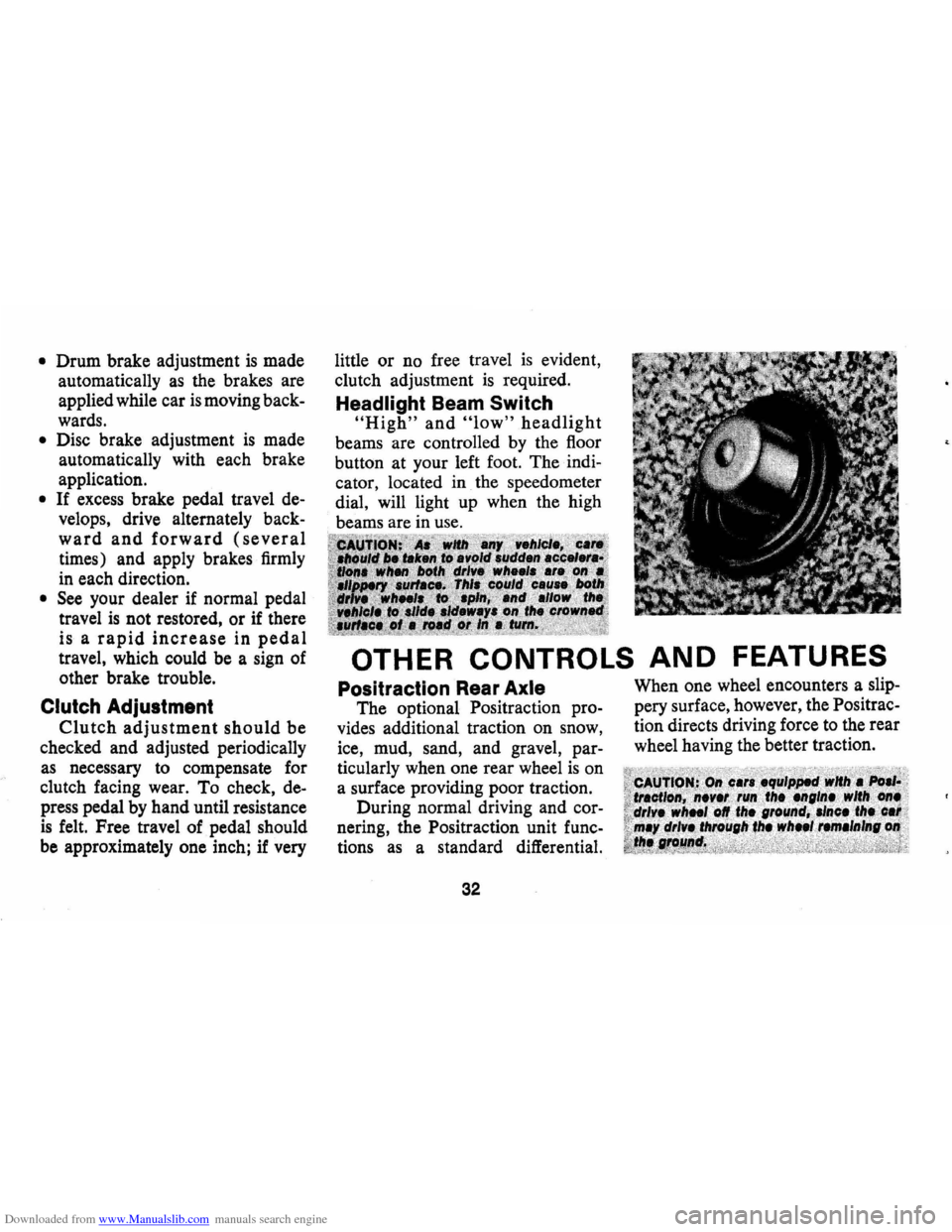
Headlight Beam Switch
"High" and "low" headlight
beams are controlled by the floor
button at your left foot. The
indi
cator, located in the speedometer
dial, will light up when the high
beams are in use.
OTHER CONTROLS AND FEATURES
Positraction Rear Axle
The optional Positraction pro
vides additional traction on snow,
ice, mud, sand, and gravel,
par
ticularly when one rear wheel is on
a surface providing poor traction.
During normal driving and
cor
nering, the Positraction unit func
tions as a standard differential.
32
When one wheel encounters a slip
pery surface, however, the Positrac
tion directs driving force to the rear
wheel having the better traction.